TMG TMG-SDT36 User manual

36-IN SKID STEER TRENCHER
PRODUCT MANUAL
MODEL: TMG-SDT36
Please read the product manual completely before assembly Check
against the parts list to make sure all parts are received
Wear proper safety goggles or other protective gears while in assembly
Missing parts or questions on assembly?
Please call: 1-877-761-2819 or email: cs@tmgindustrial.com
Do not return the product to dealer, they are not equipped to handle your
requests
WWW.TMGINDUSTRIAL.COM
Toll Free:1-877-761-2819

TABLE OF CONTENTS
TO THE OWNER..................................................................................................................................2/22
SAFETY PRECAUTIONS.....................................................................................................................3/22
TRENCHER ASSEMBLIES..................................................................................................................7/22
OPERATION INSTRUCTIONS.............................................................................................................10/22
MAINTENANCE INSTRUCTIONS.......................................................................................................12/22
STORAGE INSTRUCTIONS................................................................................................................13/22
SPECIFICATIONS................................................................................................................................14/22
W W W. T M G I N D U S T R I A L . C O M P 1 / 22 T o l l F r e e : 1 - 877-761-2819

TO THE OWNER
GENERAL COMMENTS
Congratulations for having this trencher! Your trencher was carefully designed
and manufactured to give you years of dependable service. Your trencher will
require some minor maintenance(such as cleaning and lubricating) to keep it in
top working condition.
Be sure to observe all safety precautions and maintenance procedures as
described in this manual.
ABOUT THIS MANAL
This manual has been designed to help you do a better and safer job. Read this
manual carefully and become familiar with its contents. Remember, never let
anyone operate this unit without reading the "Safety Precautions" and
"Operation Instructions" sections of this manual. Unless noted otherwise, right
and left sides are determined from the position of the skid steer operator sitting
in the seat facing forward.
SERVICE
When service your trencher, pls. remember to use only manufacturer
replacement parts. Substitute parts may not meet the standards required for
safe, dependable operation. To facilitate parts ordering, pls. record the model
No. and serial No. of the metal plate on your unit.
W W W . T M G I N D U S T R I A L . C O M P 2 / 22 To l l F r e e : 1 - 877-761-2819

SAFETY PRECAUTIONS
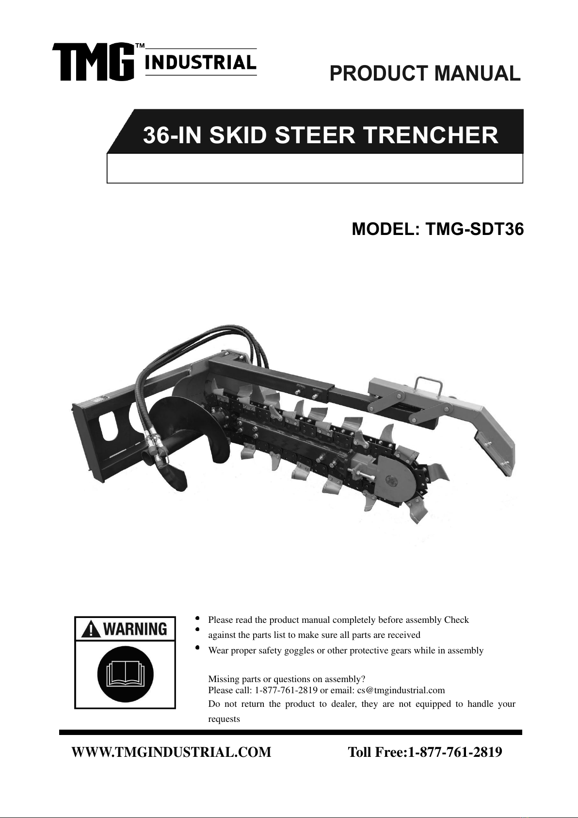
The trenchers are designed to be easy to use and maintain. They are operated
by the skid steer auxiliary hydraulics. The trenchers mount to the toolbar or
quick attach mechanism for easy mounting.
BEFORE OPERATION
1. The operator must read the operation manual carefully before installation,
operation or maintenance. Improper operation will cause the machine damaged
or the operator dead.
2. Read all the safe signs and safe declarations. Obey all the professional safe
terms, local laws or the professional directions.
3. Familiar with the trencher about functions, specs and operation. Replace the
to-be-damaged parts in time. Make sure all the hydraulic installations and
couplings connect firmly, and all the safe signs stick on the suitable positions
clearly.
TO THE OPERATOR
WARNING! PROTECT AGAINST FLYING DEBRIS
Always wear proper safety glasses, goggles, or a face shield when
driving pins in or out, or when any operation causes dust, flying debris,
or any other hazardous material.
2. Don’t modify the trencher casually.
3. Should keep the machine on the flat ground when repair, far away from the
transportation and other dangerous places.
4. Should use the right tools to repair.
5. Don’t operate the machine, unless you are professional, have certificates,
and familiar with its functions, specs and safe operation rules.
6. Must not leave the machine when the machine is running. Must stop the
engine at first and then remove the key if want to leave.
W W W. T M G I N D U S T R I A L . C O M P 3 / 22 T o l l F r e e : 1 - 877-761-2819

TRENCHER ASSEMBLIES
W W W. T M G I N D U S T R I A L . C O M P 10/22 T o l l F r e e : 1 - 877-761-2819
S/N
PART NO.
PART DESCRIPTION
QTYS
NOTE
1
020736I-01-01
ROTATION AUGER
1
2
020736I-01-02
BOLT M14x55
6
GB5783
3
020736I-01-03
FLAT WASHER D14
6
GB97.1
4
020736I-01-04
SPRING WASHER D14
6
GB93
5
020736I-01-05
NUT M16
7
6
020736I-01-06
SPRING WASHER D16
7
7
020736I-01-07
FLAT WASHER D16
7
8
020736I-01-08
CONNECTION BUSH
1
9
020736I-01-09
CHAIN WHEEL
1
10
020736I-01-10
HEXAGON SOCKET COUNTERSUNK HEAD SCREW M6x16
6
GB2673
11
020736I-01-11
END COVER
1
12
020736I-01-12
SEALING RING
1
13
020736I-01-13
SPACE BUSH
1
14
020736I-01-14
DRIVING SHAFT
1
15
020736I-01-15
BEARING
2
16
020736I-01-16
MOUNTING FRAME
1

TRENCHER ASSEMBLIES
W W W. T M G I N D U S T R I A L . C O M P 11/22 T o l l F r e e : 1 - 877-761-2819
S/N
PART NO.
PART DESCRIPTION
QTYS
NOTE
17
020736I-01-17
REAR MOUNTING BRACKET
1
18
020736I-01-18
HEXAGON HEAD BOLT M16x60
6
GB5783
19
020736I-01-19
FLAT WASHER D16
4
20
020736I-01-20
SPRING WASHER D16
4
21
020736I-01-21
HEXAGON HEAD BOLT M16x50
4
22
020736I-01-22
MOTOR
1
MOTOR USED SEALS
23
020736I-01-23
END THROUGH
1
24
020736I-01-24
END THROUGH
2
25
020736I-01-25
DISCHARGE OIL PIPE
1
26
020736I-01-26
MAIN OIL PIPE
2
27
020736I-01-27
HEXAGON HEAD BOLT M14x55
4
28
020736I-01-28
ELASTIC SHAFT CLAMP
1
29
020736I-01-29
GREASE NIPPLE
1
30
020736I-01-30
BEARING SEAT
1
31
020736I-01-31
BOLT M16x130
1
32
020736I-01-32
O SEALING RING
1

TRENCHER ASSEMBLIES
W W W. T M G I N D U S T R I A L . C O M P 1 3 / 22 T o l l F r e e : 1 - 877-761-2819
S/N
PART NO.
PART DESCRIPTION
QTYS
NOTE
1
020736I-02-01
BOLT M16x130
4
GB5783
2
020736I-02-02
SPRING WASHER D16
4
GB93
3
020736I-02-03
FLAT WASHER D16
4
GB97.1
4
020736I-02-04
CHAIN TENSION SET
1
5
020736I-02-05
BOLT M16x40
4
GB5783
6
020736I-02-06
NUT M16
4
GB6170
7
020736I-02-07
MOVABLE SET
1
8
020736I-02-08
HEXAGON SOCKET HEAD M20x130
2
GB70
9
020736I-02-09
NUT M20
2
GB6170
10
020736I-02-10
BOLT M12x30
1
GB5783
11
020736I-02-11
PIN
2
12
020736I-02-12
ELASTIC HOLE CLIP
1
13
020736I-02-13
TENSION WHEEL
1
14
020736I-02-14
BEARING
1
15
020736I-02-15
SQUARE BUSH
1
16
020736I-02-16
SQUARE SHAFT
1

TRENCHER ASSEMBLIES
W W W. T M G I N D U S T R I A L . C O M P 15/22 T o l l F r e e : 1 - 877-761-2819
S/N
PART NO.
PART DESCRIPTION
QTYS
NOTE
1
020736I-03-01
BOLT M12x55
4
2
020736I-03-02
FLAT WASHER D12
4
3
020736I-03-02
SPRING WASHER D12
4
4
020736I-03-04
NUT M12
4
5
020736I-03-05
SOIL COLLECTION FRAME
1
6
020736I-03-06
BOLT M12x40
4
GB5783
7
020736I-03-07
TELESCOPIC INNER FRAME
1
8
020736I-03-08
BOLT M12x100
4
9
020736I-03-09
CONNECITONING ROD
4
10
020736I-03-10
FLAT WASHER D16
4
11
020736I-03-11
SOIL COLLECTION FRAME
1
12
020736I-03-12
BOLT M12x35
4
13
020736I-03-13
NYLON PLATE
1
14
020736I-03-13
SPRING
1

TRENCHER ASSEMBLIE
W W W. T M G I N D U S T R I A L . C O M P 1 7 / 22 T o l l F r e e : 1 - 877-761-2819
S/N
PART NO.
PART DESCRIPTION
QTYS
NOTE
1
020736I-04-01
CHAIN
58KNOTS
2
020736I-04-02
RIGHT ALLOY TOOTH
4
3
020736I-04-02
FLAT WASHER D12
64
GB97.1
4
020736I-04-04
BOLT M12x40
8
GB5783
5
020736I-04-05
LEFT COMMONG TOOTH
11
6
020736I-04-06
NUT M12
58
GB5783
7
020736I-04-07
SPRING WASHER D12
58
GB93
8
020736I-04-08
BOLT M12x35
42
GB5783
9
020736I-04-09
RIGHT COMMONG TOOTH
10
10
020736I-04-10
LEFT ALLOY TOOTH
4

OPERATION INSTRUCTIONS
The trencher can dig a trench with 900mm depth and 200mm width. Attach the
trencher to the toolbar or quick attach mechanism of your skid steer loader.
RAISING OR LOWERING THE TRENCHER
raise or lower the trencher by raising or lowering the skid steer loader arms
through their appropriate skid steer controls.
TILTING THE TRENCHER
Tilt the trencher up or down by tilting the toolbar or attachment plate back or
forward through its skid steer controls. We recommend a 60 degrees angle for
general trenching as measured from the ground level(the horizon).
STARTING AND STOPPING THE TRENCHER
Power to the trencher is supplied by oil from the skid steer auxiliary hydraulic
system, which passes through the hydraulic hoses and into the trencher's
hydraulic motor. The trencher itself has no one on or off control, but is
operated by the skid steer auxiliary hydraulic control mechanism. To start the
trencher, engage the auxiliary hydraulics. To stop the trencher, disengage the
auxiliary hydraulics.
TRENCHER SPEED CONTROL
The power of the trencher is supplied by the skid steer's auxiliary hydraulics.
Trencher speed and power are determined by the flow of oil coming out of the
auxiliary system, which in turn is dependent upon skid steer engine speed. To
increase trencher speed, increase skid steer engine speed, on the contrary, to
decrease trencher speed, decrease skid steer loader speed.
When first starting a trench throttle down the skid steer engine to half throttle.
This will reduce the shock to the skid steer and trencher when the digging
teeth first contact the ground. Once the trench is started, set the engine back to
the full throttle. For the general use, operate the trencher with skid steer engine
at full throttle to provide maximum power to the auxiliary hydraulics.
W W W. T M G I N D U S T R I A L . C O M P 1 8 / 22 T o l l F r e e : 1 - 877-761-2819

OPERATION INSTRUCTIONS
AUGER HEIGHT
The auger is fixed to the trencher mainframe and has no separate adjustment.
To raise the auger, raise the trencher as previously described. This will raise
the auger to leave the dirt or spoil closer to the trench.
CHAIN TENSION ADJUSTMENT
When trenching, the digging chain tension should be adjusted to let the chain
is as loose as possible, without jumping off the sprocket or Idler wheel. In the
left of the trencher arm end, should have an adjustment bolt with a jam nut, to
tighten the chain, need rotate the adjustment bolt to the proper position, and
turn the standard nut to the adjustment bolt, will push the boom out and thus
tighten the chain. To loosen the chain, just use the opposite method.
NOTE 1:
It is common for your trencher to need its digging chain tightened after the first
10 to 20 minutes of operation as the chain and sprocket seat themselves.
NOTE 2:
Don't trench stones or hard soils, to prevent damage to the digging teeth of the
trencher. If the digging teeth wear severely, should replace them timely, to
ensure the normal work.
W W W . T M G I N D U S T R I A L . C O M P 19/22 T o l l F r e e : 1 - 877-761-2819
Table of contents
Other TMG Construction Equipment manuals