jbc SFR-B User manual

Solder Feeder for Automation
Ref. SFR-B
INSTRUCTION MANUAL
www.jbctools.com
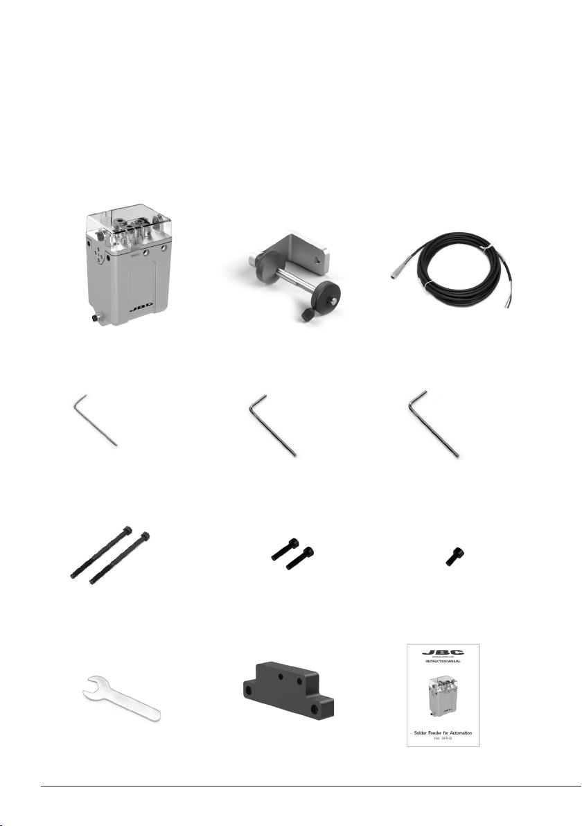
Packing List
The following items are included:
Allen Key 1,5 mm ......... 1 unit
Ref. 0741610
Reel Support ................. 1 unit
Ref. 0024561
Solder Feeder for
Automation .................... 1 unit
Ref. SFR-B
Communications
Cable 3 m........................ 1 unit
Ref. 0024563
Spanner 10 mm............. 1 unit
Ref. 0017631
Allen Key 2,5 mm ......... 1 unit
R ef. 0 012574
Screws
DIN 912 M4x65.......... 2 units
Ref. 0024552
Screws
DIN 912 M4x20........ 2 units
Ref. 0921890
Manual ............................ 1 unit
Ref. 0024557
Insulator ........ 1 unit
Ref. 0024588
Allen Key 3 mm ......... 1 unit
Ref. 0013609
Screws
DIN 7991 M4x10........ 1 unit
Ref. 0490180
2
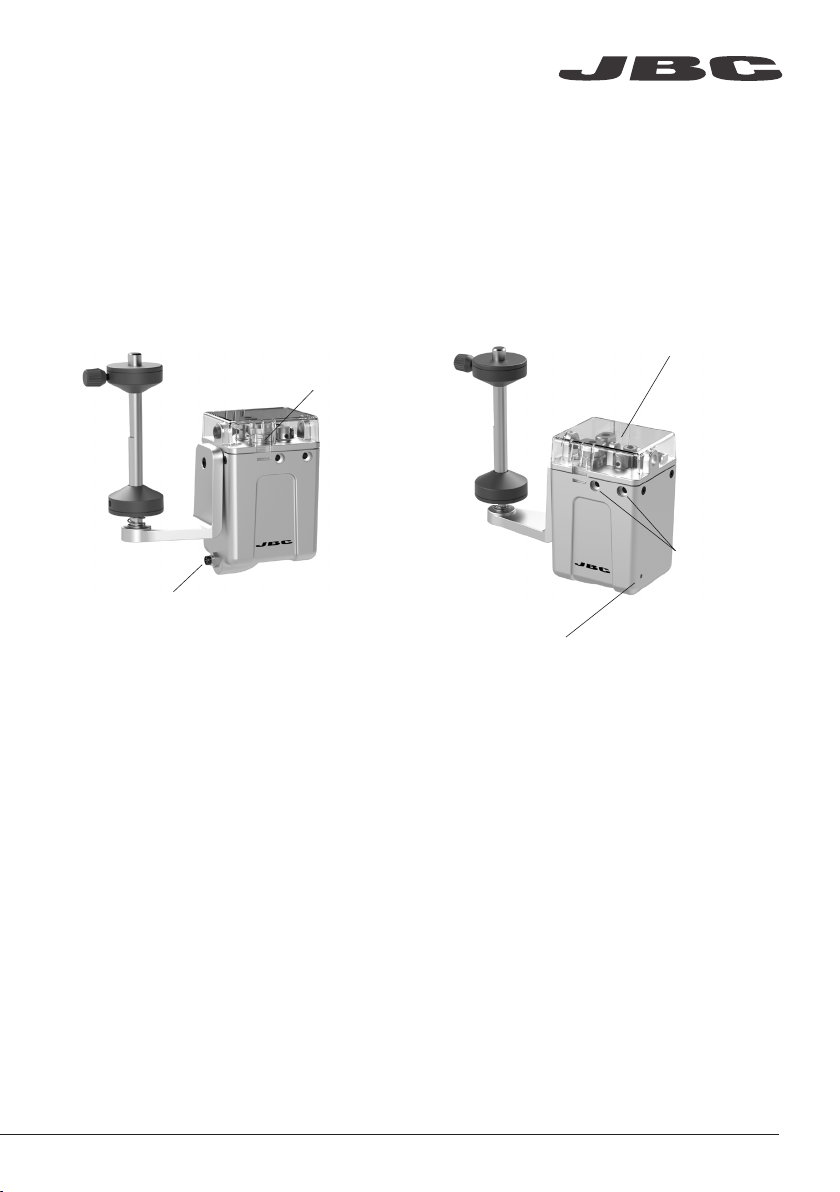
Features
Communications and Power
Connector
LED Indicator:
· Blue: device powered
· Green: device working
· Red blinking: error, no solder wire
or device is blocked
Assembling
holes
The SFR Solder Feeder works together with one of the different GSFR Guide Kits, available for the various solder
wire diameters, with or without solder wire perforation. GSFR kits are sold separately.
Drag mechanism
Lid with
push tabs
www.jbctools.com
3
1 3
5
2 4
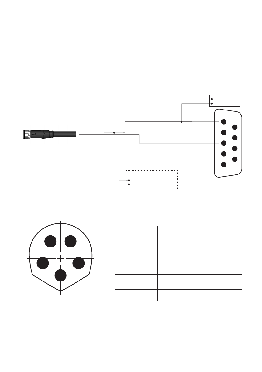
Transmitted data - Grey cable
Optional:
Pedal activation by
relay or digital output
Ground - Blue cable
Brown cable
Black cable
Received data - White cable
Female DB9
Connector
5
4
9
8
7
6
3
2
1
Connection
- The SFR unit can be connected to a PLC by a five-pin Communications Cable (Ref. 0020261).
- Connect the cables to the corresponding pins to match your PLC connection. To comunicate with
a computer use a DB9 female connector.
- Download the Robot Communication Protocol at www.jbctools.com
Communications Cable
Ref. 0020261
For detailed information about pin distribution see following table:
Front view
SFR Communications Connector
Pin Distribution
Pin Color Description
1 Brown Power supply input:
24Vdc (±5%). 1.5 A current required
2 White Serial input: RS232 RX
3 Blue Common reference:
GND for RS232 and witch
4 Black Switch input: 0V or 24V to start feeding.
Leave it open to stop
5 Grey Serial output: RS232 TX
V+ 24 Vdc
V- 1.5 A
4
1
3
2
4
1
3
2
4
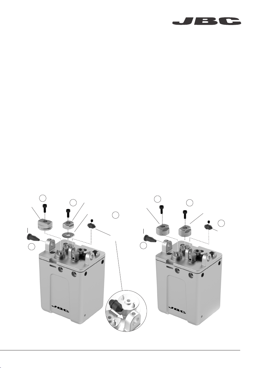
Assembly: GSFR* Wheels to SFR
For this operation, disconnect the device, and dismantle the cover by pushing the tabs at both sides
of the lid. Use the allen key and the spanner to assemble the following components.
1. Insert the Intermediate Nozzle until its collar rests against the housing and tighten the screw.
2. Assemble the Guide Wheel and tighten the screw. If you use a Guide Kit without Solder
Wire Perforation assemble the Support Wheel.
Attention: Always use the correct wheel set for each wire thickness.
3. If you have a Guide Kit with Solder Wire Perforation assemble the Blade first, then mount the
Blade Clamp onto the same axis and tighten the screw. If you use a Guide Kit without Solder
Wire Perforation, assemble the Traction wheel.
Caution: handle the blade carefully to avoid injury.
4. Insert the Inlet Nozzle into the hole and tighten the screw.
GSFR* with Solder Wire Perforation GSFR* without Solder Wire Perforation
Blade
Blade Clamp
Inlet
Nozzle
Inlet
Nozzle
Guide
Wheel Traction
Wheel
Support
Wheel
Inter.
Nozzle
Inter.
Nozzle
*Not included, sold separately
www.jbctools.com
5
4
2
1
3
5
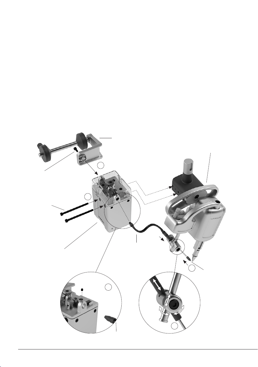
1. Assemble the SFR to the TRA with the screws.
2. Assemble the GSFR Guide Tube to the TRA and adjust its position, then tighten the screw.
3. Assemble the Outlet Nozzle onto the Dispensing Tube.
4. Assemble the GSFR Bushing into the SFR hole and tighten the screw.
5. Attach the Reel Support to the SFR with its screws.
Assembly: SFR to TRA*
Solder Feeder
for Automation
Ref. SFR-B
GSFR Guide Tube*
Soldering Head
for Automation*
Ref. RBA-B
Reel Support
Ref. 0024561
Screws
Ref. 0024552
Screw
Ref. 0490180
GSFR Bushing*
*Not included, sold separately
Outlet Nozzle*
The guide position
can be adjusted in
angle, height and
length
6
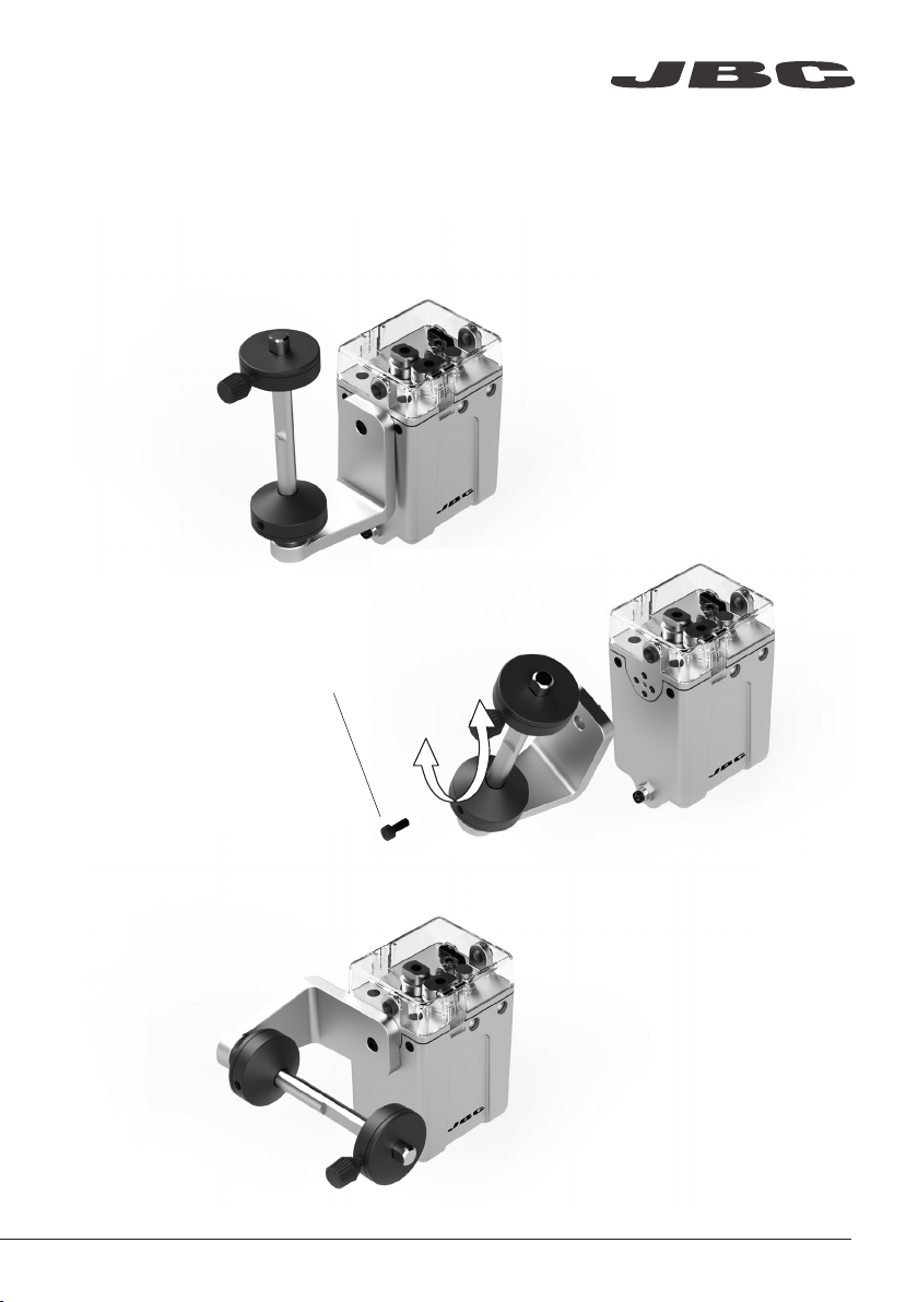
Assembly: Reel support positions
The reel support can be installed both vertically and horizontally to match your preferences.
Unscrew the bolt using a 3mm allen key and set the support as desired.
Tighteen the bolt to lock the support.
Loosen the bolt
completely before
repositioning the
support.
Vertical Reel
Support
Horizontal Reel
Support
www.jbctools.com
7

Assembly: SFR independent from TRA*
Screws
Ref. 0014954
Solder Feeder
for Automation
Ref. SFR-B
Insulator
Ref. 0021713
Screws
Ref. 0921890
If mounting SFR independently from TRA, the Electrical Insulator is required.
Assemble the Insulator to your device with its screws, followed by the SFR to The insulator with its
screws.
The Electrical Insulator must be assembled for the tool to work properly.
*Not included, sold separately
Do not use the SFR without insulator if it is mounted without the TRA.
8

Solder Wire Loading
The GSFR must be assembled previously.
1. Feed the Solder Wire into the Inlet Nozzle until it reaches the wheels.
2. Make sure the wire passes through the Intermediate Nozzle and enters into the Guide Tube.
Wire feeding is controlled by an external controller (Robot/PLC/Computer). See the Robot Commu-
nication Protocol for SFR unit at www.jbctools.com/jbcsoftware.html
Solder Wire
2
1
Wheels
Inlet
Nozzle
Guide
Tube
Intermediate
Nozzle
Intermediate
Nozzle
www.jbctools.com
9

Dimensions (Vertical Reel Suport)
Solder Wire Reel dimensions: max. lenght 80mm (3.2 in), max. diameter 80mm (3.2 in), max. weight 1 kg (2.2 lb).
mm
(in)
10
Table of contents


