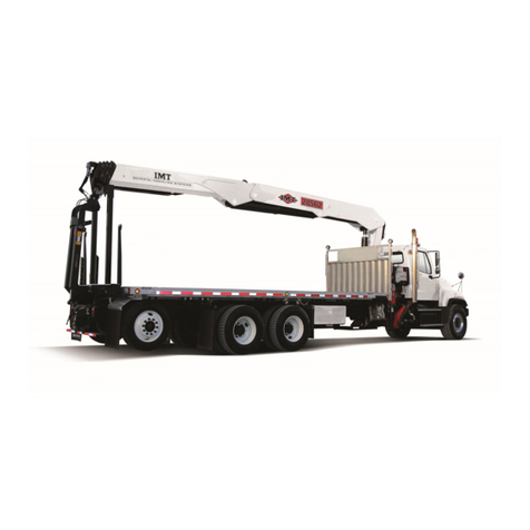
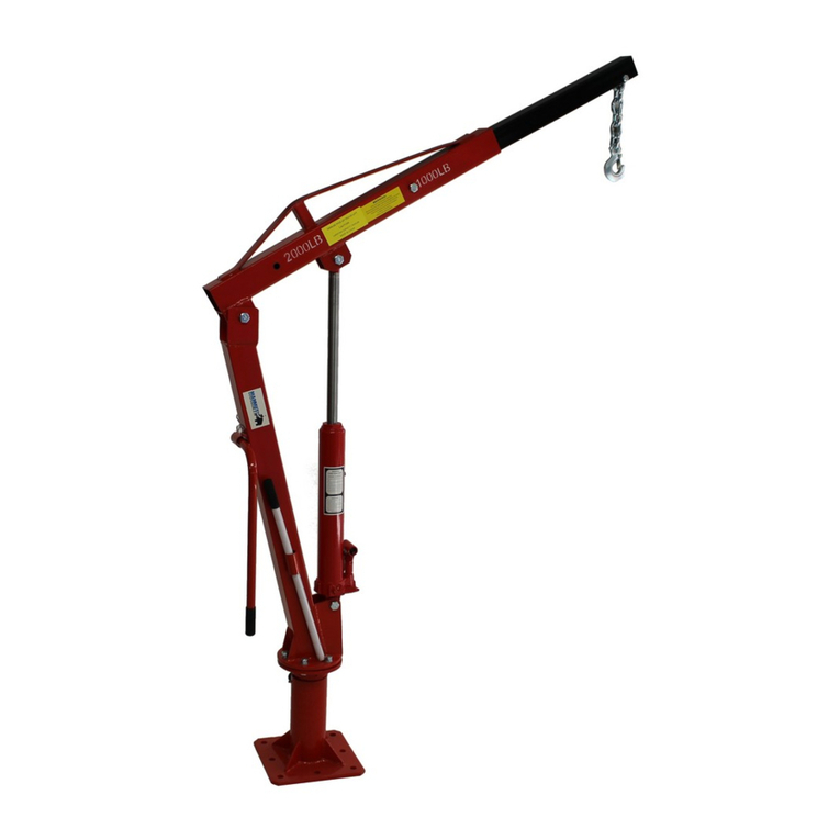
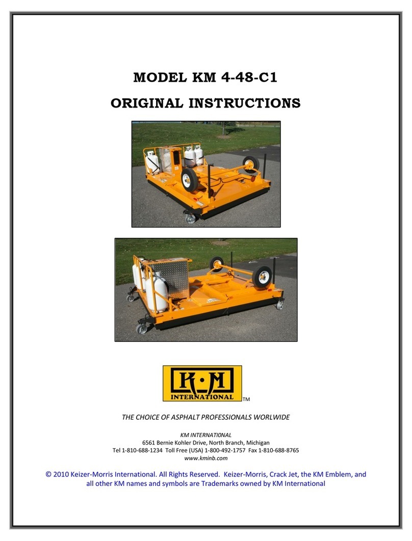
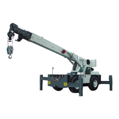
IMT 5525 User manual

5525/6025/6625:99903289:
Model 5525 Crane
Model 6025 Crane
Model 6625 Crane
IOWA MOLD TOOLING CO., INC.
BOX 189, GARNER, IA 50438-0189
TEL: 641-923-3711
MANUAL PART NUMBER 99903289
20040302
Section 1 CRANE SPECIFICATIONS
Section 2 CRANE REFERENCE
Section 3 REPLACEMENT PARTS
Section 4 GENERAL REFERENCE
Volume 2 - PARTS AND SPECIFICATIONS
6625
Manual Effective Through July, 2004

5525/6025/6625:99903289:
REVISIONS LIST
DATE LOCATION DESCRIPTION OF CHANGE
--------
20011126 3-4,9,10,19,20 ECN #8828 - CHANGE LOWER BOOM WELDMENT TO ADD MACH. BUSHINGS
20011210 2-4 REMOVED WINCH BEARING GREASE NOTE
2-7 EDITED INSTALLATION ITEM #2 - BOLT SPECS.
3-8 ADDED REPAIR NOTE
3-9 ADDED ITEM 8 TO TORQUE NOTES
20011220 3-29 ADDED 99903340 CHASSIS WIRING HARNESS
20020208 1-1-3, ADDED 5 ADDED 5525 SPECIFICATIONS TO MANUAL
2-5,6 ADDED 5525 SPARE PARTS
3-4,6,12,15,29 NEW WINCH, WINCH KIT, CYLINDER, LOWER BOOM ASM. AND DECAL DRAWING
20020219 3-9 BASE ASM 41716514 - GEAR ROTATOR WAS 71056574, NOW 71056577
20020225 3-23-26, 29-32, ECN 8833 - ADDED RADIO REMOTE CONTROL & HYDRAULIC KITS FOR ALL
35-38 MODELS AND STANDARD CONTROL & HYD KIT FOR 5525
20020416 3-1, 43-50 ECN 8909 - ADDED 5525 RCLC DECAL TO KIT, RENUMBERED PAGES
20020422 2-6, 3-23 CORRECTED SPARE PARTS LIST, ECN 8910 - NEW HOSE LENGTHS IN HYD KIT
20020508 3-23,42,44 ECN 8915 - CHANGES TO HOSE & DECAL KIT
3-31-38 ECN 8913 - CHANGES WIRING HARNESS
3-50 ECN 8914 - ADDED DOM 1 BOOM SUPPORT
20020821 3-12-14, 19-20, 31, ECN 8966 - VARIOUS CHANGES
33,35,37,41
3-50 ADDED BACKUP RMT HANDSET, 51716912, TO MANUAL
20021114 3-4,5 ECN9059 - ADDED LOCKING COLLAR TO WINCH KIT
ECN 9050 (ref) - WIRE ROPE WINDING CHANGE
3-35,37 ECN 9008 - CONTROL KITS (90717398, 90717156)
20030325 3-39 CORRECTED ERROR ON O-RING PART NO. - ITEM #6 IS 7Q072013
3-18 ECN 9142 - NEW PRESSURE SWITCH PARTS ON C-BAL VALVE 73540094
20030410 3-31-34, 35,37,40-41 CONTROL KITS - CORRECTED WIRE HARNESSES AND ADDED TETHERED REMOTE
CABLES; CORRECTED CABLES FOR RADIO REMOTES; ADDED VALVEBANK FOR
RADIO REMOTE
20030611 3-34 CORRECTED NOTE - “J” IS WEATHERPACK SHROUD, NOT TOWER
20030707 2-11 ECN 9195 - CHANGES FOR 2002 FORD SUPERDUTY WIRING
20030908 3-23-29 ECN 9207 - UPDATE TO SWIVELS ON HYDRAULIC KITS
3-31-43 ECN 9211 - CONTROL KIT & HARNESS CHANGES. ADDED HARNESS DWGS.
3-44 ADDED NUT PART NUMBER TO VALVEBANK (TS)
3-55 ADDED NOTE TO 51716912
20040302 1-8-10 ADDED REDUCED CAPACITY INSTRUCTIONS

5525/6025/6625:99903289: INTRODUCTION
Read and familiarize yourself with the
IMT OPERATOR'S CRANE SAFETY MANUAL
before operating or performing any maintenance
on your crane.
20010915
This volume deals with information applicable to your
particular crane. For operating, maintenance and
repair instructions, refer to Volume 1, OPE ATION,
MAINTENANCE AND EPAI .
We recommend that this volume be kept in a safe
place in the office.
This manual is provided to assist you with ordering
parts for your IMT crane. It also contains additional
instructions regarding your particular installation.
It is the users responsibility to maintain and operate
this unit in a manner that will result in the safest
working conditions possible.
Warranty of this unit will be void on any part of the
unit subjected to misuse due to overloading, abuse,
lack of maintenance and unauthorized modifications.
No warranty - verbal, written or implied - other than the
official, published IMT new machinery and equipment
warranty will be valid with this unit.
In addition, it is also the users responsibility to be
aware of existing Federal, State and Local codes and
regulations governing the safe use and maintenance
of this unit. Listed below is a publication that the user
should thoroughly read and understand.
ANSI/ASME B30.5
MOBILE and LOCOMOTIVE C ANES
The American Society of Mechanical Engineers
United Engineering Center
345 East 47th Street
New York, NY 10017
Three means are used throughout this manual to gain
the attention of personnel. They are NOTEs,
CAUTIONs and WA NINGs and are defined as
follows:
NOTE
A NOTE is used to either convey additional
information or to provide further emphasis for a
previouspoint.
CAUTION
A CAUTION is used when there is the very strong
possibilityofdamage to theequipment or premature
equipmentfailure.
WARNING
A WARNING is used when there is the potential for
personalinjuryor death.
Treat this equipment with respect and service it
regularly. These two things can add up to a safer
workingenvironment.

5525/6025/6625:99903289:20010915 NOTES

5525/6025/6625:99903289: 1-120020208
SECTION 1: SPECIFICATIONS
GENERAL SPECIFICATIONS .................................................................................... 2
PERFORMANCE CHARACTERISTICS .................................................................... 3
POWER SOURCE ...................................................................................................... 3
CYLINDER HOLDING VALVES ................................................................................. 3
ROTATION SYSTEM ................................................................................................... 3
HYDRAULIC SYSTEM................................................................................................ 3
EXCESSIVE LOAD LIMIT SYSTEM (ELLS) .............................................................. 3
WINCH - 6025 & 6625 MODELS ................................................................................ 3
WINCH - 5525 MODEL ............................................................................................... 3
MINIMUM CHASSIS SPECIFICATIONS ..................................................................... 4
GEOMETRIC CONFIGURATION ................................................................................ 4
5525 CAPACITY CHART ............................................................................................ 5
6025 CAPACITY CHART ............................................................................................ 6
6625 CAPACITY CHART ............................................................................................ 7
REDUCED CAPACITY LIFT CHARTS ....................................................................... 8
STABILITY CONFIRMATION PROCESS ................................................................... 9

5525/6025/6625:99903289: 1-2
IOWA MOLD TOOLING CO., INC.
BOX 189, GARNER, IA 50438-0189
TEL: 641-923-3711 FAX: 641-923-2424
MODELS 5525, 6025 AND 6625 CRANE SPECIFICATIONS
20020208
GENERAL SPECIFICATIONS 5525 6025 6625
CRANE RATING 55,000 ft-lb 60,000 ft-lb 66,000 ft-lb
(7.6 ton-meters) (8.3 ton-meters) (9.1 ton-meters)
HORIZONTAL REACH 25’-4” (7.7 m) 25’-4” (7.7 m) 25’-4” (7.7 m)
from centerline of rotation
HYDRAULIC EXTENSIONS (2) 78” & 78” 78” & 78” 78” & 78”
(198.1 cm & 198.1 cm) (198.1 cm & 198.1 cm) (198.1 cm & 198.1 cm)
LIFTING HEIGHT 26’-7” (8.1 m) 26’-7” (8.1 m) 26’-7” (8.1 m)
from base of crane
CRANE WEIGHT 2,350 lb (1,065.9 kg) 2,350 lb (1,065.9 kg) 2,350 lb (1,065.9 kg)
OUTRIGGER SPAN - required option
crane side from centerline of chassis 90'’ (228.6 cm) 90'’ (228.6 cm) 90'’ (228.6 cm)
opposite crane side from 48'’ (121.9 cm) 48'’ (121.9 cm) 48'’ (121.9 cm)
centerline of chassis
CRANE STORAGE HEIGHT 40” (101.6 cm) 40” (101.6 cm) 40” (101.6 cm)
MOUNTING SPACE REQUIRED 20” x 21” 20” x 21” 20'’ x 21'’
crane base (50.8 cm x 53.3 cm) (50.8 cm x 53.3 cm) (50.8 cm x 53.3 cm)
OPTIMUM PUMP CAPACITY 10 U.S. gpm 10 U.S. gpm 10 U.S. gpm
(37.9 L/min) (37.9 L/min) (37.9 L/min)
SYSTEM OPERATING PRESSURE 3,000 psi (206.8 bar) 3,000 psi (206.8 bar) 3,000 psi (206.8 bar)
CENTER OF GRAVITY
horizontal from centerline of rotation 41” (104.1 cm) 41” (104.1 cm) 41” (104.1 cm)
vertical from bottom of crane base 22” (55.9 cm) 22” (55.9 cm) 22” (55.9 cm)
TIE-DOWN BOLT PATTERN 14-3/4” x 14-3/4” 14-3/4” x 14-3/4” 14-3/4” x 14-3/4”
8 bolts (37.5 cm x 37.5 cm) (37.5 cm x 37.5 cm) (37.5 cm x 37.5 cm)
ROTATIONAL TORQUE 9,000 ft-lb (1.2 tm) 9,000 ft-lb (1.2 tm) 9,000 ft-lb (1.2 tm)

5525/6025/6625:99903289: 1-320020208
PERFORMANCE CHARACTERISTICS
ROTATION: 400° (6.98 rad) 33 seconds
LOWER BOOM ELEVATION: -5° to +75° (-0.09 rad to +1.31 rad) 11 seconds (6025 Model)
12 seconds (6625 Model)
EXTENSION CYLINDERS (2): 78" & 78” (198.1 cm & 198.1 cm) 27 seconds total
PLANETARY GEAR LINE SPEED 60 feet per minute (6025 & 6625 Models)
WORM GEAR LINE SPEED (5525 Model)
First layer 25 ft/min
Second layer 27 ft/min
Third layer 30 ft/min
POWER SOURCE
Hydraulic power is provided by an integral mounted hydraulic pump and pto. Other standard power
sources may be utilized. Minimum power required is 23.5 horsepower based on 10 gpm at 3,000 psi
(38 L/min at 207 bar).
CYLINDER HOLDING VALVES
The holding sides of all cylinders are equipped with integral mounted counterbalance valves or load-
holding check valves to prevent sudden cylinder collapse in case of hose or other hydraulic component
failure.
ROTATION SYSTEM
Rotation of the crane is accomplished through a turntable gear bearing powered by a high-torque
hydraulic motor through a self-locking worm. Standard rotation is 400°.
HYDRAULIC SYSTEM
The hydraulic system is an open-centered, full pressure system with pump requiring 10 US gpm (38 L/
min) optimum oil flow at 3000 psi (207 bar). It consists of a four-section, electric remote, stack-type
control valve with a 40 ft (12.2 m) control pendant. The system includes a hydraulic oil reservoir, suction
line filter, return line filter and control valve.
EXCESSIVE LOAD LIMIT SYSTEM (ELLS)
The ELLS limits overloading of the crane. Dual pressure switches mounted on the lift cylinder sense
various overload conditions. When in an overload situation, the winch up, extension out, and boom
down functions are stopped. To relieve the situation, raise the boom, retract the extensions, or lower the
winch.
WINCH - 6025 & 6625 MODELS
The 5,500 lb capacity planetary winch is powered by a high-torque hydraulic motor. The lifting capacity
of the winch is 5,500 lb (2,495 kg) one-part line. Maximum two-part line winch capacity is 10,500 lb
(4.762 kg). The winch is equipped with 100 ft (30.5 m) of 7/16” (1.1 cm) 6x25 FW PRF RRL IWRC
XIPS wire rope. A compact, anti-two block device is included to prevent the lower block or hook
assembly from coming in contact with the boom sheave assembly. The winch meets ANSI B30.5
standards.
WINCH - 5525 MODEL
The winch is powered using a hydraulic motor driving a 27:1 worm gear arrangement with a mechanical
brake. Maximum single line lifting capacity of the winch, achieved on the second layer of wire rope, is
5500 lb (2495 kg). Maximum two-part line winch capacity is 10,400 lb (4717 kg). The winch is equipped
with 100 ft (30.5 m) of 7/16” (1.1 cm) 6 x 25 FW PRF RRL IWRC XIPS wire rope. Nylon sheaves are
located at the tip of the extension boom. An anti-two block device is included to prevent the lower block
or hook assembly from coming in contact with the boom sheave assembly. The winch meets ANSI
B30.5 standards.

5525/6025/6625:99903289: 1-420010915
GEOMETRIC CONFIGURATION
MINIMUM CHASSIS SPECIFICATIONS
Chassis Style Conventional Cab
Front Axle Rating (GAWR) 9,000 lb (4,082.3 kg)
Rear Axle Rating (GAWR) 17,000 lb (7,711.0 kg)
Wheelbase 154" (391.2 cm)
Cab-to-Axle 84" (213.4 cm)
Resistance to Bending Moment (RBM) 800,000 in-lb (9,217 kg-m)
Frame Section Modulus 16 cubic inches (262.2 cc)
Frame Yield Strength 50,000 psi (3,447.4 bar)
Gross Vehicle Rating 26,000 lbs (11793 kg)
Transmission 5-speed
In addition to these specifications, heavy duty electrical and cooling systems are required. It is recommended that
the vehicle be equipped with an engine tachometer, auxiliary brake lock, and power steering.
IMT reserves the right to change specifications or design without notice.
6'-10"
(2.08 cm)
5'-2"
(1.58 m)
3'-6"
(1.07 m)
26'-7"
(8.11 m)
20'-4"
(6.20 m)
14'
(4.27 m)
3'-4"
(1.02 m) 1'-10" (55.9 cm)
1'-4"
(40.6 cm) 12'-4"
(3.76 m) 25'-4"
(7.72 m)
24.75"
(62.9 cm)
25.5"
(64.8 cm)
ROTATIONAL CLEARANCE
3.31"
(8.4 cm)
MOUNTING HOLES AS VIEWED
FROM THE TOP OF THE CRANE
14.75"
(37.5 cm)
6.87" TYP
(17.4 cm)
7.38" TYP
(18.7 cm)
14.75"
(37.5 cm)
6.44"
(16.4 cm)

5525/6025/6625:99903289: 1-520020225
XXXX lb
XXXX kg
REACH IN FEET
CAPACITY IN POUNDS
(METERS)
(KILOGRAMS)
Weight of load handling devices
are part of the load lifted and must
be deducted from the capacity.
IOWA MOLD TOOLING CO., INC.
BOX 189, GARNER, IA 50438-0189
TEL: 641-923-3711 FAX: 641-923-2424
70396149
5525 HYDRAULIC CAPACITY CHART
CENTERLINE
25'
20'
15'
10'
26'-7"
2'-2"
06'-6"
(1.98m)
3'-7"
(1.09m)
9'-0"
(2.74m)
15∞
45∞
60∞
75∞
18'-10"
(5.74m)
12'-4"
(3.75m)
16'-2"
(4.92m)
22'-8"
(6.90m)
25'-4"
(7.72m)
5'
(4.57m)
(0.66m)
(1.52m)
(3.04m)
(6.09m)
(7.62m)
(8.10m)
3185
(1445)
5515
(2502)
5630
(2554)
7400
(3357)
8990
(4078)
5810
(2635)
10,500
(4763)
6290
(2853)
4625
(2098)
3155
(1431)
2600
(1179)
2105
(955)
1840
(835)
6300
(2858)
7760
(3520)
3635
(1649)
4075
(1848)
4930
(2236)
2815
(1277)
3870
(1755)
3330
(1510)
2715
(1232)
2400
(1089)
4990
(2263)
3580
(1624)
2960
(1343)
2400
(1089)
2100
(953)
3990
(1810)
4460
(2023)
30∞
See reduced capacity placard for
additional information if applicable.
Values in the box denote
the use of 2 part line.
Maximum 1 part line is 5500 lb (2495 kg).

5525/6025/6625:99903289: 1-620010920
Maximum 1 part line is 5500 lb (2494 kg).
Values in the box denote
the use of 2 part line.
See reduced capacity placard for additional
information if applicable.
XXXX lb
XXXX kg
REACH IN FEET
CAPACITY IN POUNDS
/ METERS
/ KILOGRAMS
Weight of load handling devices
are part of the load lifted and must
be deducted from the capacity.
IOWA MOLDTOOLING CO., INC.
BOX 189, GARNER, IA 50438-0189
TEL: 641-923-3711 FAX: 641-923-2424
70396096
6025 HYDRAULIC CAPACITY CHART
CENTERLINE
25'
20'
15'
10'
26'-7"
2'-2"
06'-6"
(1.98m)
3'-7"
(1.09m) 9'
(2.74m)
15˚
45˚
60˚
75˚
18'-10"
(5.74m)
12'-4"
(3.75m) 16'-2"
(4.92m) 22'-8"
(6.90m) 25'-4"
(7.72m)
5'
(4.57m)
(0.66m)
(1.52m)
(3.04m)
(6.09m)
(7.62m)
(8.10m)
3500
(1588)
5540
(2513)
6510
(2953)
8570
(3887)
9910
(4495)
6330
(2871)
10500
(4763)
6720
(3048)
5040
(2286)
3490
(1583) 2880
(1306) 2340
(1061) 2070
(939)
7220
(3275)
8410
(3815)
3980
(1805)
4460
(2023)
5380
(2440)
3090
(1402)
4240
(1923)
3650
(1656)
2990
(1356)
2650
(1202)
5000
(2268)
3830
(1737)
3260
(1479)
2660
(1207)
2350
(1066)
4260
(1982)
4870
(2208)
30˚

5525/6025/6625:99903289: 1-720010920
Maximum 1 part line is 5500 lb (2494 kg).
Values in the box denote
the use of 2 part line.
See reduced capacity placard for additional
information if applicable. XXXX lb
XXXX kg
REACH IN FEET
CAPACITY IN POUNDS
/ METERS
/ KILOGRAMS
Weight of load handling devices
are part of the load lifted and must
be deducted from the capacity.
IOWA MOLDTOOLING CO., INC.
BOX 189, GARNER, IA 50438-0189
TEL: 641-923-3711 FAX: 641-923-2424
70396054
6625 HYDRAULIC CAPACITY CHART
CENTERLINE
25'
20'
15'
10'
26'-7"
2'-2"
06'-6"
(1.98m)
3'-7"
(1.09m)
9'
(2.74m)
15˚
45˚
60˚
75˚
18'-10"
(5.74m)
12'-4"
(3.75m)
16'-2"
(4.92m)
22'-8"
(6.90m)
25'-4"
(7.72m)
5'
(4.57m)
(0.66m)
(1.52m)
(3.04m)
(6.09m)
(7.62m)
(8.10m)
3900
(1769)
6100
(2766)
7200
(3265)
9500
(4309)
10500
(4763)
7025
(3186)
10500
(4763)
7400
(3356)
5625
(2551)
3900
(1769)
3250
(1474)
2620
(1202)
2325
(1054)
8025
(3640)
9300
(4218)
4425
(2007)
4975
(2256)
5975
(2710)
3450
(1564)
4750
(2154)
4000
(1814)
3325
(1508)
2975
(1349)
5500
(2494)
4200
(1905)
3600
(1632)
2975
(1349)
2620
(1202)
4675
(2120)
5350
(2426)
30˚

5525/6025/6625:99903289: 1-8
REDUCED CAPACITY LIFT CHARTS
The Reduced Capacity Lift Chart System was
conceived to inform the end user of the allow-
able loads which can be lifted off the sides of a
mechanics truck. IMT devised a color-coded
chart defining the sectors where less than full
hydraulic crane capacity can be lifted. The
color-coded chart (Reduced Capacity Lift Chart
or RCLC) corresponds to a visual indicator on
the base of the crane. The RCLC displays the
percentage of the full hydraulic crane capacity to
be lifted in each sector. The visual indicator on
the crane base gives the operator a reference of
the sectors. With this information the end user
can more safely use the mechanics truck.
Stability confirmation yields data to produce a
Reduced Capacity Lift Chart if necessary.
Some units may not require derating over the
sides, but a majority will.
ILLUSTRATION - REDUCED CAPACITY COLOR-CODED CHART
If the IMT crane is installed by an IMT distributor,
the distributor is responsible for stability confir-
mation. IMT supplies a generic RCLC decal for
dealer installation.
CAUTION:
CHASSIS WEIGHT, SUSPENSION, AND UNIT SET
UP, INCLUDING NUMBER AND TYPE OF
OUTRIGGERS, LIFTING SURFACE, ETC., HAVE A
SIGNIFICANT IMPACT ON STABILITY.
The basic illustration graph shows full crane
capacity off the rear of the truck and reduced
capacity when lifting over the sides. Lifting over
the front of the truck is not permitted.
For an IMT 5525 crane with a standard IMT
Dominator II body, the derated percentage is
80% in the yellow quandrants. For an IMT 6025
crane with a standard Dominator II body, the
derated percentage is 70% in the yellow quad-
rants.
20040225
60
120
90
CAB
FILL IN %
CAPACITY CHART
PERMITTED
LIFTING NOT
PERMITTED IN
THIS AREA
FILL IN %
CAPACITY CHART
PERMITTED
100% OF CAPACITY
CHART PERMITTED
(INCLUDES TRUCK BED AREA)
TRUCK
BED

5525/6025/6625:99903289: 1-9
STABILITY CONFIRMATION PROCESS
To confirm stability,
1) Set up unit on a hard, flat surface which
meets SAE J765 requirements. Use all recom-
mended equipment such as outriggers, etc.
2) Position the crane at full, horizontal reach.
For a 5525 crane, use a 2,172 ± 10 lb test
weight suspended over the rear of the truck.
For a 6025 crane, use a 2443 ± 10 lb test weight
suspended over the rear of the truck. Rotate the
test weight up to the point where the pointer on
the crane base meets the yellow bands on both
sides of the unit. If the unit keeps at least one
rear tire firmly touching the ground, the test can
be continued for the capacity on the sides. If the
criterion is not met for the rear of the unit, a
custom RCLC is required. Please contact IMT
for assistance in this situation.
NOTE: The tire is touching the ground when at
least 90% or more of the tread surface is
contacting the ground.
Once stability is verified over the rear section of
the truck, test the stability on the sides of the
truck. Again, using the test weight in a fully
extended, horizontal position, rotate the crane
around the sides of the truck. If the test weight
passes the sides with at least one rear tire
firmly touching the ground, a standard Hydraulic
Capacity Chart may be used rather than a
Reduced Capacity Lift Chart.
CAUTION
THE UNIT MAY TILT SEVERELY!
If the unit does not pass the side load test, you
must begin retracting the booms to find the
usable percentage of the crane capacity.
For a 5525 crane, retract the booms 42” for a
capacity derating to 80%. For a 6025 crane,
retract the booms 63” for a capacity derating to
70%. Measure from a fixed point on the boom
tip horizontally to a fixed point on the main boom
to verify how far the booms have been re-
tracted. See table.
Once the booms are retracted, re-check stabil-
ity by again rotating the crane around the sides
of the truck, making sure the weight passes by
the yellow region marked on the crane base with
at least one rear tire firmly touching the ground.
Test both sides of the truck. If the crane cannot
rotate through the yellow zone with at least one
rear tire firmly touching the ground, you must
work with IMT for a custom Reduced Capacity
Lift Chart. In this situation, please contact IMT
for assistance.
CAUTION
DO NOT LIFT IN THE “NO LIFTING ZONE.”
Follow safe crane practices throughout the
testing. Keep the load as close to the ground as
possible.
3) The minimum 90° “No Lifting Zone” over the
cab must be on ALL Reduced Capacity Load
Charts. The zone may need to be increased if
front outriggers are not used. In addition, the
stability may be greater on one side of the unit
than the other, but IMT has chosen to keep both
ratings the same. Thus, the lowest stability
percentage is reported for each side.
Install the RCLC decal on the inside of the crane
compartment door.
Keep a record of the reduced stability test to
verify the decals in case replacement is neces-
sary.
20040225
CRANE TEST PERCENT DISTANCE BOOMS ARE
MODEL WEIGHT RATED RETRACTED FROM FULL
LOAD (%) EXTENSION (INCHES)
5525 2,172 ± 10 lb 80% 42”
6025 2,443 ± 10 lb 70% 63”

5525/6025/6625:99903289: 1-10

2-15525/6025/6625:99903289: 20010915
SECTION 2: CRANE REFERENCE
MAJOR CRANE ASSEMBLIES ...................................................................................... 3
GREASE ZERK LOCATIONS & LUBRICANT REQUIREMENTS ................................. 4
RECOMMENDED SPARE PARTS LIST ........................................................................ 5
CONTROL VALVE TROUBLESHOOTING .................................................................... 9
ELEC SCHEMATIC (99903 87) ...................................................................................
WINCH BRAKE HARNESS & DUAL PRESSURE SYSTEM ...................................... 2
ANTI TWO-BLOCKING DEVICE .................................................................................. 3
Excessive Load Limit System (ELLS) TEST PROCEDURE ..................................... 4
ELLS TROUBLESHOOTING PROCEDURE ............................................................... 8

2-25525/6025/6625:99903289: NOTES
20010915

2-35525/6025/6625:99903289:20010915
MAJOR CRANE ASSEMBLIES
BASE
MAST
WINCH
LOWER BOOM
LOWER
CYLINDER
EXTENSION
CYLINDERS
(INTERNAL)
1ST STAGE
EXTENSION BOOM
2ND STAGE
EXTENSION BOOM
6625

2-45525/6025/6625:99903289:
1. TURNTABLE/BEARING GREASE EXTENSION
*ROTATE CRANE WHILE GREASING
4. LOWER CYLINDER
5. MAST/LOWER BOOM
6. LOWER CYLINDER ROD
7. UPPER SHEAVE PIN
8. LOWER SHEAVE PIN
. SNATCH BLOCK PIN
2. WORM GEAR (FWD)*
3. WORM GEAR (REAR)*
* Apply 3 pumps then rotate crane fully
ITEM LOCATION DESCRIPTION LUBRICANT FREQUENCY
SHELL ALVANIA 2EP
OR
SHELL RETINAX A
WEEKLY
GREASE ZERK LOCATIONS & LUBRICANT REQUIREMENTS
NOTE: All application points except 2 & 3 ust be greased weekly under nor al work loads and oderate weather
conditions. Under severe operating conditions, lubrication should be perfor ed ore frequently. See Volu e 1;
Operation, Maintenance and Repair for additional lubrication require ents.
EXTREME PRESSURE
EP2 GREASE
EVERY 3 MONTHS
20011210
1
2
3
54
69
7
8
6625

2-55525/6025/6625:99903289:RECOMMENDED SPARE PARTS LIST
1 YEAR SUPPLY
MODEL 5525/ 6025 / 6625 TELESCOPING CRANE
FOR MANUAL: 99903289
This spare parts list does not necessarily indicate that the items can be expected to fail in the course of a year. It is intended to provide the
user with a stock of parts sufficient to keep the unit operating with the minimal down-time waiting for parts. There may be parts failures not
covered by this list. Parts not listed are considered as not being critical or normal wear items during the first year of operations and you need
to contact the distributor or manufacturer for availability.
QTYDESCRIPTIONPART NO.ITEM NO.
Base Assembly 41716514
(ALL) 73051919 Hydraulic Motor 1
Mast Assembly 41716515
(ALL) 72601629 Cap Screw .75-10 x 4.00 8
72060209 Cap Screw .75-10 x 2.75 14
Lower Boom Assembly 70146462 5525- ower Cylinder 1
(ALL) 70146427 6025 - ower Cylinder 1
70146304 6625 - ower Cylinder 1
73540094 Block C-bal w/dbl Pressure Switch 1
73540052 Valve- Counter Balance 1
77041625 Pressure Switch 3100 psi 1
77041626 Pressure Switch 3500 psi 1
70145753 Port Tube-Base 1
70145927 Port Tube-Rod 1
60122982 Wear Pad 1
60122985 Wear Pad-Mushroom 2
70055203 Bushing-Garlock 2
77041251 Relay 1
5525 Lower Cylinder 70146462 075TC0064 Rod Weldment 1
060KT0007 Head 1
050KE0008 Piston 1
092KT0010 Seal Kit 1
70055225 Bushing-Garlock 4
6025 Lower Cylinder 70146427
075TC0058 Rod Weldment 1
060 T0007 Head 1
050 E0013 Piston 1
092 T0059 Seal Kit 1
70055225 Bushing-Garlock 4
6625 Lower Cylinder 70146304
075TC0058 Rod Weldment 1
060 T0008 Head 1
050 E0011 Piston 1
092 T0056 Seal Kit 1
70055225 Bushing-Garlock 4
E tension Boom Assembly 41716517
(ALL) 51716461 Extension Cylinder Assembly
60122981 Wear Pad 1
60122984 Wear Pad-Cylinder 1
60122980 Wear Pad 1
60122983 Wear Pad 1
60122985 Wear Pad-Mushroom 2
60030255 Sheave 2
20020228
ASSEMBLY DESIGNATION

2-65525/6025/6625:99903289:
Extension Cylinder Assembly 51716461
(ALL) 001EE0006 Port Tube 2
075RD0015 Rod Weldment-1st Stage 1
075RC0059 Rod Weldment-2nd Stage 1
060FR0007 Head-1st Stage 1
060FR0006 Head-2nd Stage 1
050FE0016 Piston-1st Stage 1
050FE0015 Piston-2nd Stage 1
092FR0012 Seal Kit-1st Stage 1
092FR0013 Seal Kit-2nd Stage 1
114BB0024 Valve-Counterbalance 1
Winch, Cable & Hook Kit
(ALL) 70580143 Cable Assembly 1
51713168 Cord Reel 1
77041459 Limit Switch 1
60030313 Sheave-Snatch Block 1
71073035 Hook 1
70732882 Hook 1
70074004 Safety Latch 1
60122358 Downhaul Weight 1
72661367 Pin 1
73733171 Pin 1
5525 Worm Gear Winch 70570198
73051513 Motor 1
70055117 Pillow Block 1
76393419 Oil Seal 1
70143948 Bushing 1
70143949 Bushing 1
76393420 O-ring 1
76394300 Gasket 1
76393171 Gasket 1
6025 & 6625 Planetary Winch 70146319
70146399 Motor 1
70146400 Seal Kit 1
70146402 Valve-Counter Balance 1
6025 & 6625 Hydraulic Kit 91716519
73540090 Solenoid Valve-Brake 1
Valve Bank 73733395
(ALL) 73054934 Proportional Valve 1
73054935 Relief Valve 1
77041518 Coil-Sections 4
77041556 Coil- Proportional Valve 1
Installation Kit
(ALL) 73052006 Filter Element- 10 Micron 1
Remote Control Handle 51713182
(ALL)
70394183 Trigger Assembly 1
77040371 Switch SPST 1
77040372 Switch SPDT 2
77040373 Switch SPST 1
77040374 Switch SPDT 1
20020422
QTYDESCRIPTIONPART NO.ITEM NO.
ASSEMBLY DESIGNATION
Other manuals for 5525
2
This manual suits for next models
2
Table of contents
Other IMT Construction Equipment manuals
