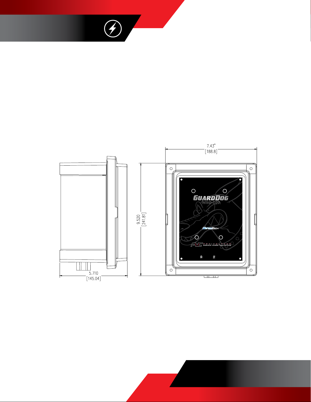
MAXIVOLT GuardDog WRG-100 Owner's manual

WRG-100
WRG-200
WRG-200N
WRG-300
WRG-400
WRG-400P
WRG-600
WRG-700P
GuardDog® Series
INSTALLATION, OPERATION, & MAINTENANCE
MANUAL
CONTENTS
Important Notes
Installation Instructions, Wiring Diagrams, Dimensional Drawings
Operation and Maintenance
Warranty

Breaker must be ‘off’ during installation. Do not install surge protective device with power ‘hot’.
Do not connect any two SPD wires to the same bus. The SPD may be damaged and warranty voided by
improper connection.
30 inches of wire is provided for installation. Cut wires as short as possible and keep free of sharp
bends. Sharp bends in the wire create impedance. For optimum performance lead wire should be as short
as possible and free of sharp bends.
Do not add wire to the SPD. This will impair the performance of the SPD, and will void the warranty. The
SPD will perform best (faster response time) with the shortest wire length possible. Do not use wire nuts,
kernies, etc. when installing SPD.
Never install the SPD without utilizing mounting feet.
Do not modify the SPD in any way. The SPD may be damaged and void the warranty.
©2020 MAXIVOLT
01
GUARD DOG® SERIES
INSTALLATION, OPERATION, & MAINTENANCE
MANUAL
IMPORTANT NOTES
MUST BE INSTALLED BY LICENSED ELECTRICIAN
Safety First! Know Your Voltage!
Always Use a Volt Meter!

Read Important Notes before installing SPD. Breaker must be disconnected during installation.
Mount SPD as close as possible to connection points using mounting feet.
Use rigid conduit and fittings to pipe conductors.
Cut lead conductors as short as possible without straining or creating sharp bends to connect.
Connect SPD lead conductors in accordance with wiring diagrams on page 4.
Energize and ensure blue lights are on and primary protection lights are off.
Note: Appropriate conduits and fittings must be used to maintain NEMA 4X rating.
02
GUARDDOG® SERIES
INSTALLATION, OPERATION, & MAINTENANCE
MANUAL
©2020 MAXIVOLT
INSTALLATION INSTRUCTIONS

03
GUARD DOG® SERIES
INSTALLATION, OPERATION, & MAINTENANCE
MANUAL
©2020 MAXIVOLT
DIMENSIONAL DRAWINGS
inches
[mm]
WRG-100
WRG-200
WRG-200N
WRG-300
WRG-400
WRG-400P
WRG-600
WRG-700P
WRG-100
Primary Protection - NORMALLY OFF - CONTACT MAXIVOLT IF ON
Surge Protective Device
240/120 VAC Split Ø 3 Wire
®
ETL-EU Listed
IEC 61643-11
ETL-C-US Listed
ANSI/UL 1449-4
Secondary Protection - NORMALLY ON - CONTACT MAXIVOLT IF OFF
Designed and Manufactured in Amarillo, Texas, USA
CONTAINS NO FIELD SERVICEABLE PARTS
FOR TECHNICAL SUPPORT CALL 800.583.4773 v2
EQUIPPED WITH
REMOTE MONITORING
®

04
GUARD DOG® SERIES
INSTALLATION, OPERATION, & MAINTENANCE
MANUAL
©2020 MAXIVOLT
WIRING DIAGRAMS
WRG-100
WRG-200
WRG-300
WRG-400
WRG-600
WRG-200N
WRG-400P
WRG-700P
Phase A
Phase B
Neutral
WRG-100
Primary Protection - NORMALLY OFF - CONTACT MAXIVOLT IF ON
Surge Protective Device
240/120 VAC Split Ø 3 Wire
®
ETL-EU Listed
IEC 61643-11
ETL-C-US Listed
ANSI/UL 1449-4
Secondary Protection - NORMALLY ON - CONTACT MAXIVOLT IF OFF
Designed and Manufactured in Amarillo, Texas, USA
CONTAINS NO FIELD SERVICEABLE PARTS
FOR TECHNICAL SUPPORT CALL 800.583.4773 v2
EQUIPPED WITH
REMOTE MONITORING
®
Control Power Source (Primary)
Normally Open (NO) Output (Primary)
Normally Closed (NC) Output (Primary)
Control Power Source (Secondary)
Normally Open (NO) Output (Secondary)
Normally Closed (NC) Output (Secondary)
To Phase A
To Phase B
To Phase C
To Neutral
Control Power Source (Primary)
Normally Open (NO) Output (Primary)
Normally Closed (NC) Output (Primary)
Control Power Source (Secondary)
Normally Open (NO) Output (Secondary)
Normally Closed (NC) Output (Secondary)
WRG-200
Primary Protection - NORMALLY OFF - CONTACT MAXIVOLT IF ON
Surge Protective Device
208/120 VAC 3 Ø 4 Wire
®
ETL-EU Listed
IEC 61643-11
ETL-C-US Listed
ANSI/UL 1449-4
Secondary Protection - NORMALLY ON - CONTACT MAXIVOLT IF OFF
Designed and Manufactured in Amarillo, Texas, USA
CONTAINS NO FIELD SERVICEABLE PARTS
FOR TECHNICAL SUPPORT CALL 800.583.4773 v2
EQUIPPED WITH
REMOTE MONITORING
®
Phase A
(Hi-Leg)Phase B
Phase C
Neutral
WRG-200N
Primary Protection - NORMALLY OFF - CONTACT MAXIVOLT IF ON
Surge Protective Device
240/120 VAC 3 Ø 4 Wire
®
ETL-EU Listed
IEC 61643-11
ETL-C-US Listed
ANSI/UL 1449-4
Secondary Protection - NORMALLY ON - CONTACT MAXIVOLT IF OFF
Designed and Manufactured in Amarillo, Texas, USA
CONTAINS NO FIELD SERVICEABLE PARTS
FOR TECHNICAL SUPPORT CALL 800.583.4773 v2
EQUIPPED WITH
REMOTE MONITORING
®
Control Power Source (Secondary)
Normally Open (NO) Output (Secondary)
Normally Closed (NC) Output (Secondary)
Control Power Source (Primary)
Normally Open (NO) Output (Primary)
Normally Closed (NC) Output (Primary)
Control Power Source (Secondary)
Normally Open (NO) Output (Secondary)
Normally Closed (NC) Output (Secondary)
Control Power Source (Primary)
Normally Open (NO) Output (Primary)
Normally Closed (NC) Output (Primary)
Phase A
Phase B
Phase C
WRG-400P
Primary Protection
- NORMALLY OFF - CONTACT MAXIVOLT IF ON
Surge Protective Device
480 VAC 3 Ø 3 Wire
®
ETL-EU Listed
IEC 61643-11
ETL-C-US Listed
ANSI/UL 1449-4
Secondary Protection - NORMALLY ON - CONTACT MAXIVOLT IF OFF
Designed and Manufactured in Amarillo, Texas, USA
CONTAINS NO FIELD SERVICEABLE PARTS
FOR TECHNICAL SUPPORT CALL 800.583.4773
v2
EQUIPPED WITH
REMOTE MONITORING
®

05
GUARD DOG® SERIES
INSTALLATION, OPERATION, & MAINTENANCE
MANUAL
©2020 MAXIVOLT
OPERATION AND MAINTENANCE
Add the following to your routine inspection forms:
This device contains no field serviceable parts.
VISUAL INSPECTION
Primary Protection Level
Means of Indication: Primary lights are red in color and are normally off.
Action: Visually confirm all three lights are ‘off’. If any lights are ‘on’, call Maxivolt @ 1-800-583-4773.
Secondary Protection Level
Means of indication: Secondary lights are blue in color and are normally on.
Action: Visually confirm all lights are ‘on’. If any lights are ‘off’, call Maxivolt @ 1-800-583-4773.
Technical Assistance
Maxivolt staff is available to answer any questions.
Mon. - Fri., 8:00 AM to 5:00 PM (CST/CDT) @ 1-800-583-4773

06
GUARD DOG® SERIES
INSTALLATION, OPERATION, & MAINTENANCE
MANUAL
©2020 MAXIVOLT
WARRANTY
One Year Limited Warranty
MVC, Inc. warrants to the original consumer purchaser that the electrical component parts of this WRG-Se-
ries Unit are free from defects in material and workmanship at the time of purchase under normal use and
conditions. The term of this warranty begins on the purchase date and continues for a period of one year.
In the event of a defect, or other failure of the WRG Series Unit not caused by any misuse or damage to the
WRG Series Unit while in the possession of the consumer, MVC, Inc. will repair or replace the WRG Series
unit with a new or re-manufactured equivalent, or, at MVC, Inc.’s option, refund the purchase price. Howev-
er, MVC, Inc. will not elect refund unless it is unable to provide replacement, and repair is not commercially
practicable or cannot be made within a commercially reasonable time.
THE CONSUMER IS LIMITED TO THE REPAIR OR REPLACEMENT OF THE DEFECTIVE WRG SERIES UNIT
OR REFUND OF THE PURCHASE PRICE. THIS LIMITED WARRANTY REPRESENTS THE TOTAL LIABILITY OF
MVC, INC. FOR ANY WARRANTED PART. MVC, INC. DISCLAIMS ANY OTHER EXPRESS OR IMPLIED WAR-
RANTIES INCLUDING WARRANTIES OF MERCHANTABILITY OR FITNESS FOR A PARTICULAR PURPOSE.
MVC, INC. SHALL NOT BE LIABLE FOR ANY INDIRECT, SPECIAL, INCIDENTAL, OR CONSEQUENTIAL DAMAG-
ES.
SOME STATES DO NOT ALLOW LIMITATIONS ON HOW LONG AN IMPAIRED WARRANTY LASTS, OR THE
EXCLUSION OR LIMITATION OF INCIDENTAL OR CONSEQUENTIAL DAMAGES, SO THE ABOVE LIMITATION
OR EXCLUSION MAY NOT APPLY TO YOU. THIS WARRANTY GIVES YOU SPECIFIC LEGAL RIGHTS, AND YOU
MAY ALSO HAVE OTHER LEGAL RIGHTS, WHICH MAY VARY FROM STATE TO STATE.
This warranty does not cover: (1) installation, set-up, testing, or adjustment; (2) removal or re-installation;
(3) defects occurring after purchase due to improper installation, repair, modification, accident, tampering,
misuse, abuse, or negligence; or (4) damage to the unit from fire, flood, or other catastrophe. This warranty
is void if the rated capacity of the WRG Series Unit is exceeded, if the WRG Series has been opened or dis-
assembled in any manner, or if the serial number of the WRG Series Unit has been altered or removed. This
warranty extends exclusively to the original purchaser of the WRG Series Unit, and subsequent purchasers
are not covered by this warranty agreement.
WARRANTY PROCEDURE
To obtain warranty performance, the consumer must deliver to MVC, Inc.: (1) the defective WRG Series Unit;
(2) a receipt, bill of sale, or other original evidence showing the date of purchase; and (3) the consumer’s
return address and daytime telephone number. If shipped, the WRG Series Unit must be packaged so that
it is protected from possible shipping damage, and should be addressed to: MVC, Inc., 800 S. Rusk, Ama-
rillo, Texas 79106, attention Warranty Claim. To obtain information on warranty performance, call toll free:
1-800-583-4773. A Warranty Information Form should be filled out and included in the package contain-
ing the WRG Series Unit. This form can be requested from MVC, Inc. at the toll free number listed above.

ABOUT
Established over three decades ago, Maxivolt is a pioneer in the power quality industry with over a century
of combined experience. Maxivolt manufactures specialized technology and provides value-added services
custom-tailored to extend the life and protect the operational integrity of electrical and electronic equipment.
Averted equipment failures and misoperations result in numerous long-term financial and operational benefits.
For more information, contact Maxivolt:
800-583-4773
07
GUARD DOG® SERIES
INSTALLATION, OPERATION, & MAINTENANCE
MANUAL
©2020 MAXIVOLT
This manual suits for next models
6
Table of contents
Other MAXIVOLT Surge Protector manuals
Popular Surge Protector manuals by other brands

Monster
Monster MDP 700 Instructions and warranty information

Infinite
Infinite TRANSTECTOR ALPU Series installation instructions

Embertec
Embertec EmberCeptor PC user manual

Axis
Axis TU8002-E installation guide

CPT
CPT CSF21 FB-230 installation instructions

Radial Engineering
Radial Engineering POWER-1 owner's manual