maxon motor MCD EPOS 60 W Application guide

maxon document number: 791272 -04

Hardware Reference MCD EPOS 60 W
December 2011 Edition / document number 791272-04 / subject to change maxon motor control
1Table of contents................................................................................................................... 2
2Table of figures ..................................................................................................................... 3
3Introduction ........................................................................................................................... 4
4How to use this guide............................................................................................................ 4
5Safety Instructions................................................................................................................. 5
6Performance Data................................................................................................................. 6
6.1 Motor data........................................................................................................................... 6
6.2 Electrical data...................................................................................................................... 6
6.3 Inputs .................................................................................................................................. 6
6.4 Outputs................................................................................................................................ 6
6.5 Interfaces ............................................................................................................................ 7
6.6 LED indicator....................................................................................................................... 7
6.7 Ambient temperature- / Humidity range.............................................................................. 7
6.8 Mechanical data.................................................................................................................. 7
6.9 Connections........................................................................................................................ 7
6.10 Order number...................................................................................................................... 7
7Connections .......................................................................................................................... 8
7.1 Signal connector (J1).......................................................................................................... 9
7.1.1 Digital input 7 “High Speed Command” ....................................................................... 10
7.1.2 Digital input 8 “High Speed Command” ....................................................................... 11
7.1.3 Digital input 1, 2, 3, 4 “General Purpose” .................................................................... 12
7.1.4 “+V Opto IN” external supply Input voltage for Digital Outputs.................................... 14
7.1.5 Digital output 3 and 4 “General Purpose” .................................................................... 15
7.2 Power / Communication connector (J2)............................................................................ 16
7.2.1 RS-232 communication ............................................................................................... 17
7.2.2 CAN communication.................................................................................................... 18
7.2.3 Logic supply (optional)................................................................................................. 19
7.2.4 Power supply ............................................................................................................... 20
8LED status........................................................................................................................... 21
9Dimension drawing.............................................................................................................. 21

Hardware Reference MCD EPOS 60 W
December 2011 Edition / document number 791272-04 / subject to change maxon motor control
Figure 1: MCD EPOS 60 W............................................................................................................. 4
Figure 2: EPOS documentation hierarchy....................................................................................... 4
Figure 3: Connector location........................................................................................................... 8
Figure 4: Wiring diagram (overview) ............................................................................................... 8
Figure 5: Signal connector (J1) D-Sub connector High-Density 15 poles (female)........................ 9
Figure 6: Digital input 7 “Differential” circuit .................................................................................. 10
Figure 7: Digital input 7 “Single-ended” circuit .............................................................................. 10
Figure 8: Digital input 8 “Differential” circuit .................................................................................. 11
Figure 9: Digital input 8 “Single-ended” circuit .............................................................................. 11
Figure 10: Logic level.................................................................................................................... 12
Figure 11: Digital input 1,2,3,4 ...................................................................................................... 12
Figure 12: Digital input 1, 2, 3 ,4 external wiring examples .......................................................... 13
Figure 13: Digital output 3............................................................................................................. 15
Figure 14: Power / Communication connector (J2) D-Sub connector 9 poles (male) .................. 16
Figure 15: Dimensions MCD EPOS 60 W..................................................................................... 21

Hardware Reference MCD EPOS 60 W
December 2011 Edition / document number 791272-04 / subject to change maxon motor control
This documentation “Hardware Reference” provides the hardware details of the maxon compact drive
MCD EPOS 60 W. It contains performance data, connections, specification, pin assignment and
wiring examples.
The maxon MCD EPOS 60 W is a small-sized compact drive. It
contains a brushless EC motor with Hall-sensors, digital Encoder
and a digital position control unit. The optimized commutation by
space vector control offers to drive the integrated brushless EC
motor with minimal torque ripple and low noise. The integrated
position-, velocity- and current control functionality allows
sophisticated positioning applications. It is specially designed
being commanded and controlled as a slave node in the
CANopen network. In addition the unit can be operated through
any RS-232 communication port.
The latest edition of these “Hardware Reference”, additional documentation and software to the MCD
EPOS compact drive may also be found on the internet under http://www.maxonmotor.com category
<Service & Downloads> or in the maxon motor e-shop http://shop.maxonmotor.com.
Getting Started
Cable Starting Set
Graphical User
Interface
Windows DLL
IEC1131 libraries
Firmware
Specification
Communication Guide
Application Notes
Application Samples
Figure 2: EPOS documentation hierarchy
Figure 1: MCD EPOS 60 W

Hardware Reference MCD EPOS 60 W
December 2011 Edition / document number 791272-04 / subject to change maxon motor control
Installation and starting of the equipment shall only be performed by experienced,
skilled personnel.
The user must ensure that the compact drive and the components belonging to it
are assembled and connected according to local statutory regulations.
For primary operation the compact drive should be free running, i.e. with the load
disconnected.
Any electronic apparatus is, in principle, not fail-safe. Machines and apparatus
must therefore be fitted with independent monitoring and safety equipment. If the
equipment breaks down, if it is operated incorrectly, if the control unit breaks down
or if the cables break, etc., it must be ensured that the drive or the complete
apparatus is kept in a safe operating mode.
Repairs may be made by authorized personnel only or by the manufacturer.
Improper repairs can result in substantial dangers for the user.
During installation of the MCD EPOS 60 W, make sure to disconnect all apparatus
from the electrical supply.
After switch-on, do not touch any life parts!
Make sure that the supply voltage is between 12 and 50 VDC. Voltages higher than
55 VDC or of wrong polarity will destroy the unit.

Hardware Reference MCD EPOS 60 W
December 2011 Edition / document number 791272-04 / subject to change maxon motor control
Nominal torque (max. continuous torque) ............. 54 mNm (Ta=25 °C, 5000 rpm)
1
)
Max. torque ................................................................................................ 218 mNm
Max. permissible speed (restricted by Encoder) ..................................... 12000 rpm
Max. efficiency .................................................................................................. 70 %
Torque constant .................................................................................... 24.3 mNm/A
Speed constant ......................................................................................... 393 rpm/V
Speed / Torque gradient .................................................................... 20.6 rpm/mNm
Rotor inertia .............................................................................................. 21.9 gcm2
Axial play at axial load < 6 N ....................................................................... 0 mm
> 6 N .................................................................. 0.14 mm
Radial play ................................................................................................ preloaded
Max. axial load (dynamic) ................................................................................. 5.5 N
Max. force for press fits (static) ....................................................................... 100 N
Max. radial loading, 5 mm from flange .............................................................. 25 N
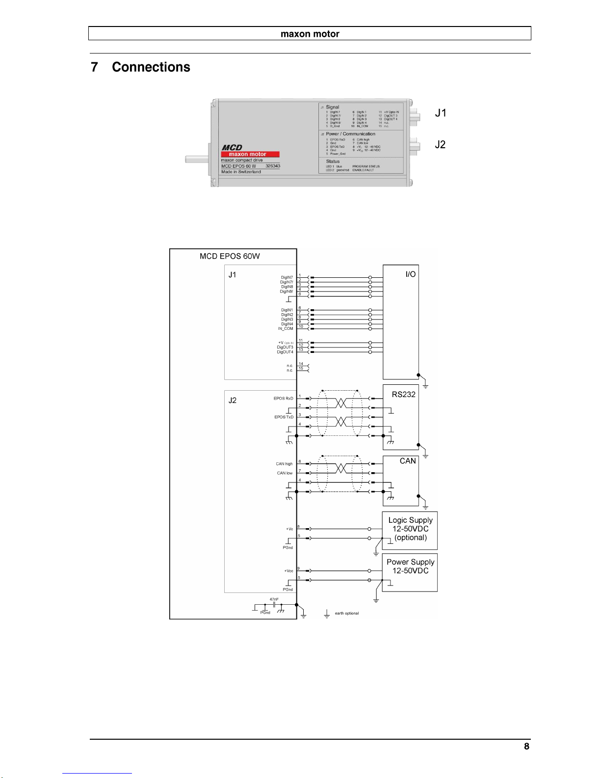
Power supply voltage VCC (Ripple < 10%) .......................................... 12 …50 VDC
Logic supply voltage VC(Ripple < 10%) (optional) ............................. 12 …50 VDC
Max. output voltage .................................................................................... 0.9 · VCC
Max. output current Imax ....................................................................................... 9 A
Continuous output current Icont ..................................... 2.6 A (Ta=25 °C, 5000 rpm)1)
Switching frequency ....................................................................................... 50 kHz
Max. efficiency .................................................................................................. 93 %
Sample rate PI - current controller ................................................................. 10 kHz
Sample rate PI - speed controller .................................................................... 1 kHz
Sample rate PID - positioning controller .......................................................... 1 kHz
Position resolution ............................................................................................ 0.09°
Position accuracy ..................................................................................... typical ± 1°
Position reproducibility ........................................................................ typical ± 0.09°
Hall sensor signals ................................. Hall sensor 1, Hall sensor 2, Hall sensor 3
Encoder signals .............................................................................. 1000 Increments
A, A\, B, B\, I, I\ (max. 200 KHz)
Digital input 1 (“General Purpose”) ........ opto-isolated ..................... +9 ... +24 VDC
Digital input 2 (“Home Switch”) .............. opto-isolated ..................... +9 ... +24 VDC
Digital input 3 (“Positive Limit Switch”) .. opto-isolated ..................... +9 ... +24 VDC
Digital input 4 (“Negative Limit Switch”) . opto-isolated ..................... +9 ... +24 VDC
Digital input 7 (“High Speed Command”) ............ line receiver EIA standard RS-422
Digital input 8 (“High Speed Command”) ............ line receiver EIA standard RS-422
+V Opto IN ...................................................................................... +12 …+24 VDC
Digital output 3 (“General Purpose”) ...... opto-isolated max. 24 VDC (IL< 350 mA)
Digital output 4 (“General Purpose”) ...... opto-isolated max. 24 VDC (IL< 350 mA)
1
)Valid at Ta=25°C, thermally isolated, no convection and 5000 rpm
Higher value (Icont max.3A) possible with better ambient conditions for example:
- free convection or forced air cooling
- thermal coupling
- lower speed

Hardware Reference MCD EPOS 60 W
December 2011 Edition / document number 791272-04 / subject to change maxon motor control
RS-232 .............................. RxD; TxD ......................................... max. 115 200 bit/s
CAN (high speed) ............. CAN_H (high); CAN_L (low) .................... max.1 MBit/s
CAN-ID, no mechanical switch, configured according to ............ LSS CiA DSP-305
Bi-colour LED .......................................................... green = ENABLE, red = FAULT
Blue LED ............................................................. is not used with MCD EPOS 60 W
Protection class ......................................................................... IP42 (optional IP54)
Operating ............................................................................................. -20 ... +85 °C
.................................................................. power derating 1.4%/K above Ta=25 °C
1
)
Storage ................................................................................................ -40 ... +85 °C
Non condensating .................................................................................... 20 ... 80 %
Max. case temperature ............................................................................... < 100 °C
Weight ................................................................................................. approx. 528 g
Dimensions (L x W x H) ................................................................ 120 x 33 x 53 mm
Mounting plate ............................................................................. for M3x4.5 screws
J1 Signal ...................................... D-Sub connector High-Density 15 poles (female)
Suitable plug: .............................................. D-Sub connector High-Density 15 poles (male)
J2 Power / Communication .................................... D-Sub connector 9 poles (male)
Suitable plug: .................................................................. D-Sub connector 9 poles (female)
MCD EPOS 60 W .........................................................................................
1
)Valid at Ta=25°C, thermally isolated, no convection and 5000 rpm
Higher value (Icont max.3A) possible with better ambient conditions for example:
- free convection or forced air cooling
- thermal coupling
- lower speed

Hardware Reference MCD EPOS 60 W
December 2011 Edition / document number 791272-04 / subject to change maxon motor control
Figure 3: Connector location
Figure 4: Wiring diagram (overview)

Hardware Reference MCD EPOS 60 W
December 2011 Edition / document number 791272-04 / subject to change maxon motor control
Signal connector contains smart multi-purpose digital I/O’s preconfigured
as: “Positive- and Negative Limit Switches” and “Home Switch”.
Additionally “General Purpose” digital I/O’s are provided.
Figure 5: Signal connector (J1) D-Sub connector High-Density 15 poles (female)
1
DigIN 7
Digital input 7 “High Speed Command”
signal
2
DigIN 7/
Digital input 7 “High Speed Command”
complement signal
3
DigIN 8
Digital input 8 “High Speed Command”
signal
4
DigIN 8/
Digital input 8 “High Speed Command”
complement signal
5
D_Gnd
Digital signal ground
6
DigIN 1
Digital input 1 “General Purpose”
7
DigIN 2
Digital input 2 “Home Switch”
8
DigIN 3
Digital input 3 “Positive Limit Switch”
9
DigIN 4
Digital input 4 “Negative Limit Switch”
10
IN_COM
Common signal for DigIN 1…4
11
+V Opto IN
External supply Input voltage for
Digital Outputs (+12 … 24VDC)
12
DigOUT 3
Digital output 3 “General Purpose”
13
DigOUT 4
Digital output 4 “General Purpose”
14
n.c.
Not connected
15
n.c.
Not connected
Accessories:
MCD EPOS signal cable
maxon order number:
Suitable connector:
D-Sub connector High-
Density 15 poles (male)

Hardware Reference MCD EPOS 60 W
December 2011 Edition / document number 791272-04 / subject to change maxon motor control
“High Speed Command” differential input by default and can be configured
via software setting.
Differential
Connector No. and Pin No.
Connector [J1] Pin number [1]
Connector [J1] Pin number [2]
Min. differential input voltage
±200 mV
Line receiver (internal)
EIA standards RS-422
Max. input frequency
500 kHz
Figure 6: Digital input 7 “Differential” circuit
Single-ended DigIN 7
Connector No. and Pin No.
Connector [J1] Pin number [1]
Input voltage
0…5 VDC
Max. input voltage
± 24 VDC
Logic 0
< 2.0 V
Logic 1
> 3.0 V
Input resistance
typical 48 kΩ
(referenced to D_Gnd)
Figure 7: Digital input 7 “Single-ended” circuit
Using the Digital Input as single ended, apply the input signal between
DigIN7 [J1/1] and D_Gnd [J1/5] and let DigIN7/ [J1/2] unconnected.

Hardware Reference MCD EPOS 60 W
December 2011 Edition / document number 791272-04 / subject to change maxon motor control
“High Speed Command” differential input by default and can be configured
via software setting.
Connector No. and Pin No.
Connector [J1] Pin number [3]
Connector [J1] Pin number [4]
Min. differential Input voltage
±200 mV
Line receiver
EIA standards RS-422
Max. input frequency
500 kHz
Figure 8: Digital input 8 “Differential” circuit
Single-ended DigIN 8
Connector No. and Pin No.
Connector [J1] Pin number [3]
Input voltage
0…5 VDC
Max. input voltage
± 24 VDC
Logic 0
< 2.0 V
Logic 1
> 3.0 V
Input resistance
typical 48 kΩ
(referenced to D_Gnd)
Figure 9: Digital input 8 “Single-ended” circuit
Using the Digital Input as single ended, apply the input signal between
DigIN 8 [J1/3] and D_Gnd [J1/5] and let DigIN 8/ [J1/4] unconnected.

Hardware Reference MCD EPOS 60 W
December 2011 Edition / document number 791272-04 / subject to change maxon motor control
These opto-isolated inputs are defined as:
Digital input 1: “General Purpose”
Digital input 2: “Home Switch”
Digital input 3: “Positive Limit Switch”
Digital input 4: “Negative Limit Switch”
by default and can be configured via software setting.
Digital input 1
[DigIN 1]
Connector [J1] Pin number [6]
Digital input 2
[DigIN 2]
Connector [J1] Pin number [7]
Digital input 3
[DigIN 3]
Connector [J1] Pin number [8]
Digital input 4
[DigIN 4]
Connector [J1] Pin number [9]
Common signal
[IN_COM]
Connector [J1] Pin number [10]
Type of Input
Optical isolated
Single ended
Input voltage
0…+24 VDC
Max. input voltage
± 30 VDC
Logic 0
| Iin | < 1 mA
| Uin | < 5 VDC
Logic 1
| Iin | > 2 mA
| Uin | > 9 VDC
Figure 10: Logic level
Input current at logic 1
typical 3 mA @24 VDC
Switching delay
< 300 s @24 VDC
Figure 11: Digital input 1,2,3,4

Hardware Reference MCD EPOS 60 W
December 2011 Edition / document number 791272-04 / subject to change maxon motor control
Different types of proximity switches
Figure 12: Digital input 1, 2, 3 ,4 external wiring examples
Use of 3-wire PNP proximity switches is preferred.
Use of 3-wire NPN proximity switches needs an additional
external pull-up resistor
R ext (12V) = 1 kΩ(150mW)
R ext (24V) = 5 kΩ(120mW)
Use of 2-wire proximity switches is possible.
Consider a minimal load current of approximately 5mA should be
complied. Depending on 2-wire proximity switch an additional
parallel resistor is necessary.

Hardware Reference MCD EPOS 60 W
December 2011 Edition / document number 791272-04 / subject to change maxon motor control
An external supply voltage has to be applied for supplying the digital
optical-isolated outputs.
+V Opto IN
[+V Opto IN]
Connector [J1] Pin number [11]
Common signal
[IN_COM]
Connector [J1] Pin number [10]
Any available power supply can be used, provided it meets the minimal
requirements set below.
Supply voltage
+12…+24 VDC
Min. current *
700 mA
* If maximum load of digital outputs is required

Hardware Reference MCD EPOS 60 W
December 2011 Edition / document number 791272-04 / subject to change maxon motor control
These opto-isolated outputs are defined as “General Purpose” by default
and can be configured via software setting.
Digital output 3
[DigOUT3]
Connector [J1] Pin number [12]
Digital output 4
[DigOUT4]
Connector [J1] Pin number [13]
+V Opto IN
[+V Opto IN]
Connector [J1] Pin number [11]
Common signal
[IN_COM]
Connector [J1] Pin number [10]
Type of Output
Optical isolated
Open-Emitter
Output voltage
Uout ≥(+V Opto IN –1.5V)
Max. load current
Iload ≤350 mA
Leakage current
Ileak ≤50 μA
Switching delay
< 300 μs @ 24 VDC
Max. inductive load
2 H @ 24VDC; 500mA
Figure 13: Digital output 3

Hardware Reference MCD EPOS 60 W
December 2011 Edition / document number 791272-04 / subject to change maxon motor control
Figure 14: Power / Communication connector (J2) D-Sub connector 9 poles (male)
1
EPOS RxD
EPOS RS232 receive
2
Gnd
Ground
3
EPOS TxD
EPOS RS232 transmit
4
Gnd
Ground
5
Power_Gnd
Ground of supply voltage
6
CAN high
CAN high bus line
7
CAN low
CAN low bus line
8
+VC12-50 VDC
Logic supply voltage (optional)
+12…+50 VDC
9
+VCC 12-50 VDC
Power supply voltage
+12…+50 VDC
Accessories:
MCD EPOS
Power / RS232-CAN cable
maxon order number:
MCD EPOS
Power / CAN-CAN cable
maxon order number:
MCD EPOS
CAN termination plug
maxon order number:
Suitable connector:
D-Sub connector 9 poles (female)

Hardware Reference MCD EPOS 60 W
December 2011 Edition / document number 791272-04 / subject to change maxon motor control
RxD receive line
[EPOS RxD]
Connector [J2] Pin number [1]
Ground
[Gnd]
Connector [J2] Pin number [2]
TxD transmit line
[EPOS TxD]
Connector [J2] Pin number [3]
Ground
[Gnd]
Connector [J2] Pin number [4]
Maximum input voltage
30 V
Output voltage
typical 9 V @ 3kΩto Ground
Maximum bit rate
115 200 bit/s
Internal RS232 driver/receiver
EIA RS232 standard
Please consider your PC’s serial port maximal baud rate.
The standard baud rate setting (factory setting) is 38 400 bit/s.
Connection MCD - PC
Connector J2 pin 2 + 4 “GND”
Pin 5 “GND”
Connector J2 pin 1 “EPOS RxD”
Pin 3 “PC TxD”
Connector J2 pin 3 “EPOS TxD”
Pin 2 “PC RxD”

Hardware Reference MCD EPOS 60 W
December 2011 Edition / document number 791272-04 / subject to change maxon motor control
CAN high bus line
[CAN high]
Connector [J2] Pin number [6]
CAN low bus line
[CAN low]
Connector [J2] Pin number [7]
Ground
[Gnd]
Connector [J2] Pin number [4]
Standard type
CAN high-speed
ISO 11898 compatible
Maximum bit rate
1 MBit/s
Max. number of CAN nodes
127
Protocol
CANopen DS-301 V4.02
CAN ID
LSS CiA DSP-305
Connection EPOS - CAN
bus line CiA DS-102
Connector J2 pin 6 “CAN high”
Pin 7 “CAN_H” high bus line
Connector J2 pin 7 “CAN low”
Pin 2 “CAN_L” low bus line
Connector J2 pin 4 “Gnd”
Pin 3 “CAN_GND” Ground
Please consider your CAN Master port maximal baud rate.
The standard baud rate setting (factory setting) is 1 MBit/s.
Further CAN information may be found in the “Communication Guide”
documentation.
Use termination resistors on both ends of the CAN bus.

Hardware Reference MCD EPOS 60 W
December 2011 Edition / document number 791272-04 / subject to change maxon motor control
Logic supply
voltage
[+VC12-50 VDC]
Connector [J2] Pin number [8]
Ground of supply
voltage
[Power_Gnd]
Connector [J2] Pin number [5]
Optionally, the logic supply voltage can be sourced separately.
This allows a safe and economical power backup feature.
In case of no separate Logic supply is applied, the Logic supply will be
sourced by the Power supply voltage automatically.
Any available power supply can be used, provided it meets the minimal
requirements set out below.
Output voltage
VCmin. 12 VDC; VCmax. 50 VDC
Ripple
< 10 %
Min. Output power
PCmin. 3 W

Hardware Reference MCD EPOS 60 W
December 2011 Edition / document number 791272-04 / subject to change maxon motor control
Power supply
voltage
[+VCC 12-50 VDC]
Connector [J2] Pin number [9]
Ground of supply
voltage
[Power_Gnd]
Connector [J2] Pin number [5]
Any available power supply can be used, provided it meets the minimal
requirements set out below.
During set up and adjustment phases, we recommend separating the unit
mechanically from the machine to prevent damage due to uncontrolled
motion.
Output voltage
VCC min. 12 VDC; VCC max. 50 VDC
Ripple
< 10 %
Output current
Depending on load,
continuous min. 2.6 A
acceleration, short-time min. 9 A
The required voltage can be calculated as follows:
Operating torque MB[mNm]
Operating speed nB[rpm]
Speed constant: kn= 393rpm/V
Speed/torque gradient: n/M = 20.6 rpm/mNm
Supply voltage +VCC [Volt]
][1
9.01
)6.20(
393
1
][1
9.01
)(
1
VM
mNm
rpm
n
V
rpm
V
VM
M
n
n
k
V
BBCC
BB
n
CC
Choose a power supply capable of supplying this calculated voltage under
load. The formula takes a max. PWM cycle of 90 % and
a 1 V max. voltage drop at power stage into account.
During braking of the load, the power supply must be capable of buffering
the feed back energy, e.g. in a capacitor or shunt regulator.
When using an electronically stabilized power supply observe that the over
current protection shall not be activated in any operating state
Other manuals for MCD EPOS 60 W
1
Table of contents
Other maxon motor DC Drive manuals
Popular DC Drive manuals by other brands

Cerus Industrial
Cerus Industrial Titan GS Series Installation, operation & maintenance manual

Aura
Aura VENOM-8 owner's manual

GFA
GFA ELEKTROMAT SI 100.30 FU-55,00 10003917 10011 installation instructions

OEZ
OEZ MP-BL Series Instructions for use

PXM
PXM PX715-L0 user manual

Allen-Bradley
Allen-Bradley powerflex 700 user manual