maxon motor EC Series User manual

Edition March 2019
maxon EC motor EC-i30 with integrated electronics
Document ID: rel8710
Operating Manual
maxon motor ag Brünigstrasse 220 P.O.Box 263 CH-6072 Sachseln Phone +41 41 666 15 00 Fax +41 41 666 16 50 www.maxonmotor.com
The EC-i30 with integrated electronics is a brushless, speed-controlled
4-quadrant drive with four pole pairs. It is available as 55 Watt version
with two shaft ends:
Functions
• Commutation with Hall sensors
• Digital speed control
• Speed range: 250…6’000 rpm
• Current limitation, non-adjustable
• Overvoltage and undervoltage switch-off
• Short-term overcurrent with I2T limitation possible
• Temperature monitoring of electronics
• Protection against reverse polarity of supply voltage
• Set value speed via analog signal 0…10 V
• Speed monitor delivers speed-proportional frequency signal
• Parameter setting via power line communication (optional, by factory setting)
• Variants with control input «Enable» or «Direction»
Contents
READ THIS FIRST . . . . . . . . . . . . . . . . . . . . . . . . . . . . . . . . . . . . . . . . . . . . . . . . . . . . . . . . . . . . . . . . . . . . . . . . . . . . . . . . . . .2
1 Technical Data . . . . . . . . . . . . . . . . . . . . . . . . . . . . . . . . . . . . . . . . . . . . . . . . . . . . . . . . . . . . . . . . . . . . . . . . . . . . . . . .4
2 Installation . . . . . . . . . . . . . . . . . . . . . . . . . . . . . . . . . . . . . . . . . . . . . . . . . . . . . . . . . . . . . . . . . . . . . . . . . . . . . . . . . . . .7
3 Functional Description. . . . . . . . . . . . . . . . . . . . . . . . . . . . . . . . . . . . . . . . . . . . . . . . . . . . . . . . . . . . . . . . . . . . . . . . . .10
4 Protective Functions . . . . . . . . . . . . . . . . . . . . . . . . . . . . . . . . . . . . . . . . . . . . . . . . . . . . . . . . . . . . . . . . . . . . . . . . . . .16
5 Troubleshooting. . . . . . . . . . . . . . . . . . . . . . . . . . . . . . . . . . . . . . . . . . . . . . . . . . . . . . . . . . . . . . . . . . . . . . . . . . . . . . .16
Order
number Variant
Nominal
speed
[rpm]
Output
[W]
618864 5-wire, CW «Enable» 6’000 20
619301 5-wire, CW «Direction» 6’000 20

maxon EC motor
2Document ID:: rel8710 EC-i30 IE
Edition: March 2019 Operating Manual
© 2019 maxon motor. Subject to change without prior notice.
Safety Guidelines
Qualified
personnel
Do not engage with any work unless you possess the necessary skills.
Legal
requirements
Observe any regulation applicable in the country and/or at the site of implementation with regard to
health and safety/accident prevention and/or environmental protection.
Make sure that all associated devices and components are installed according to local regulations.
Additional safety
equipment
Be aware that, by principle, an electronic apparatus can not be considered fail-safe. Therefore, you must
make sure that any machine/apparatus has been fitted with independent monitoring and safety equip-
ment. If the machine/apparatus should break down, if it is operated incorrectly, if the control unit breaks
down or if the cables break or get disconnected, etc., the complete drive system must return – and be
kept – in a safe operating mode.
Repairs Be aware that you are not entitled to perform any repair on components supplied by maxon motor.
Danger to life Touching live wires causes death or serious injuries!
• Consider any power cable as connected to live power, unless having proven the opposite!
• Make sure that neither end of cable is connected to live power!
• Make sure that power source cannot be engaged while work is in process!
• Obey lock-out/tag-out procedures!
• Make sure to securely lock any power engaging equipment against unintentional engagement
and tag it with your name!
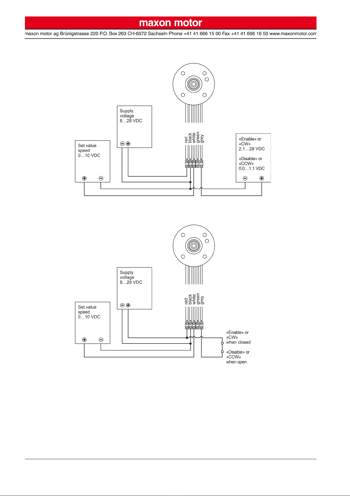
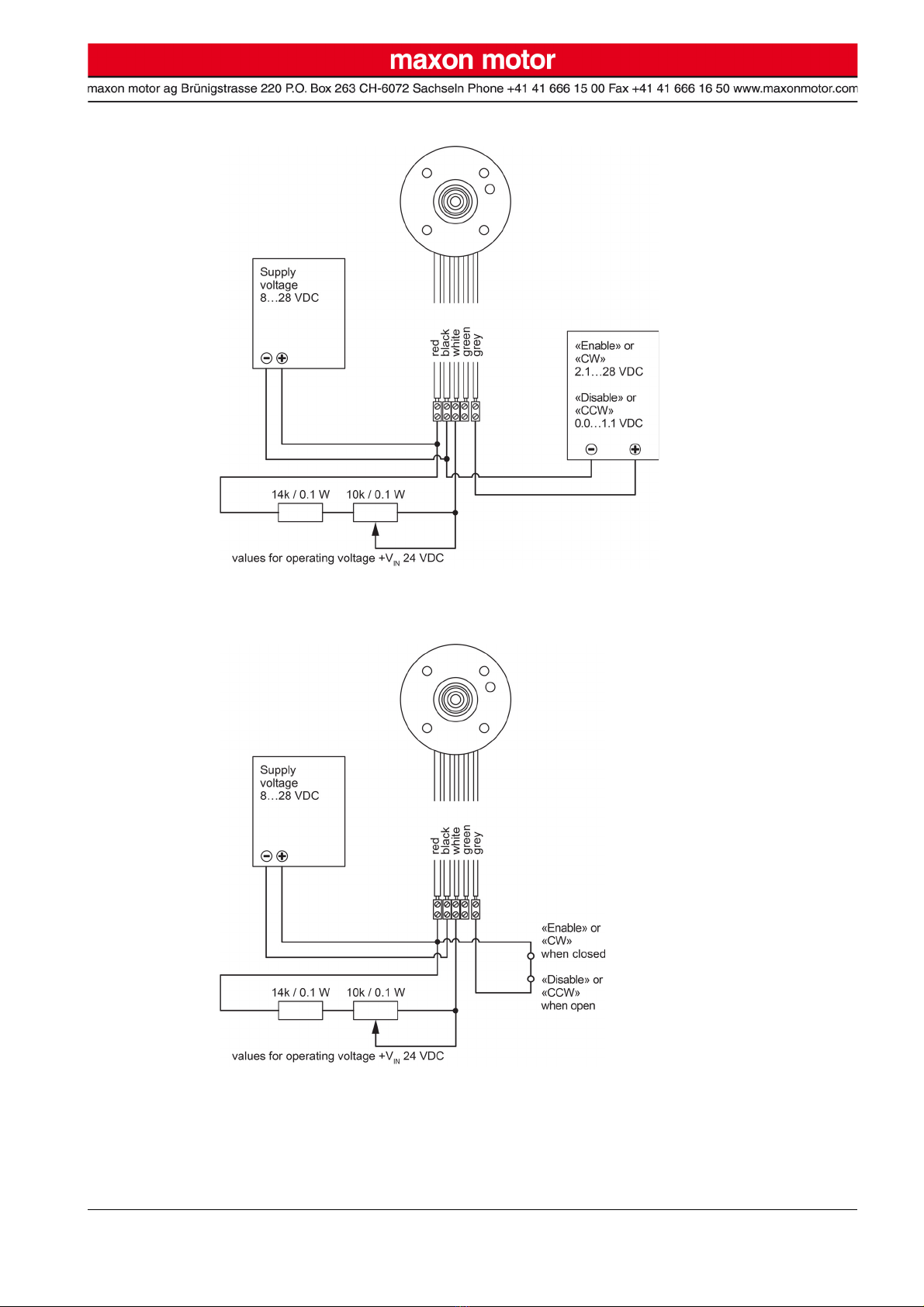
Max. supply
voltage
The connected supply voltage must be between 8 VDC and 28 VDC. Permanently applied voltages
above 30 VDC will destroy the unit.
Electrostatic sen-
sitive components
The built-in electronics can be destroyed by externally applied electronic discharges during transport,
installation, and during operation.
• Make sure to wear working cloth in compliance with ESD.
• Handle the device with extra care.
• Limit the voltage between flange and any live parts to 500 VDC
Temperature During operation, the temperature of housing, flange, or other components may exceed 60°C.
READ THIS FIRST
These instructions are intended for qualified technical personnel.
Prior commencing with any activities…
• you must carefully read and understand this manual and
• you must follow the instructions given therein.
The EC-i30 with integrated electronics is considered as partly completed machinery according to EU Directive 2006/42/
EC, Article 2, Clause (g) and is intended to be incorporated into or assembled with other machinery or other partly
completed machinery or equipment.
Therefore, you must not put the device into service,…
• unless you have made completely sure that the other machinery – the surrounding system the device is intended to
be incorporated to – fully complies with the requirements stated in the EU directive 2006/42/EC!
• unless the surrounding system fulfills all relevant health and safety aspects!
• unless all respective interfaces have been established and fulfill the stated requirements!

maxon EC motor
EC-i30 IE Document ID:: rel8710 3
Operating Manual Edition: March 2019
© 2019 maxon motor. Subject to change without prior notice.
Terms used
4-Q speed
controller
The motor produces positive torque in the selected or programmed direction. When the speed set value
is reduced or the direction changed (direction preselection version) the load is actively decelerated as to
the factory-set speed ramp.A load can be permanently decelerated.
Remark
When the load is decelerated, energy is fed back to the operating voltage supply. Thereby, the operating
voltage can undesirably increase and can damage in parallel connected consumers. Use an operating
voltage supply with feed-in possibility or a brake choppers to prevent excessive voltage surges.
Brake chopper Limits the operating voltage to a preset value as soon as its feed-in should rise above the threshold
value.
Direction
CW/CCW
As seen towards the mounting flange:
• CW = shaft turns to the right (clockwise)
• CCW = shaft turns to the left (counterclockwise)
IP40 Protected against access to dangerous parts with a wire, tool, or similar ≥Ø 1 mm and against solid for-
eign bodies ≥Ø 1 mm. No protection against water.
Max. torque
Mmax [mNm]
The maximum torque the motor can produce for a short term. It is limited by the overload protection of
the electronics.
Max. current
Imax [A]
Supply current with which the peak torque is generated at nominal voltage. With an active speed con-
troller, the supply current is not proportional to the torque, but also depends on the supply voltage. As a
result, this value only applies at nominal voltage.

maxon EC motor
4Document ID:: rel8710 EC-i30 IE
Edition: March 2019 Operating Manual
© 2019 maxon motor. Subject to change without prior notice.
1 Technical Data
All data in the document are typical values.
For detailed information consult the data sheet at the end of this document.
Motor Data
Nominal voltage VDC 24
No load speed rpm 6’000
No load current mA 107
Nominal speed rpm 6’000
Nominal torque mNm 32.6
Nominal current A 1.19
Max. torque mNm 105
Max. current A6.5
Max. efficiency %75.4
Mechanical Data
Rotor inertia g·cm2 6.69
Radial play —preloaded bearings
Max. axial load
dynamic N 9
statistic N48.8
supported N2’510
Max. radial load 10 mm from flange N30
Weight g160
Thermal Data
Thermal resistance housing/ambient air K/W-1 5.89
Thermal resistance winding/housing K/W-1 13
Thermal time constant winding s34.1
Thermal time constant motor s 1’030
Max. winding temperature °C 155
Max. temperature of electronics °C 100
Connections
Operating voltage +VIN red AWG 20 / 0.52 mm2
Operating voltage GND black AWG 20 / 0.52 mm2
Speed setpoint «Set value speed» white AWG 24 / 0.20 mm2
Speed monitor «Monitor speed» green AWG 24 / 0.20 mm2
Control input «Enable» or «Direction» grey AWG 24 / 0.20 mm2

maxon EC motor
EC-i30 IE Document ID:: rel8710 5
Operating Manual Edition: March 2019
© 2019 maxon motor. Subject to change without prior notice.
Controller Data
Operating voltage +VIN VDC +8…+28
Max. output voltage V(+VIN x 0.97) − 0.5
Output current, continuous Icont A4.5
Max. output current Imax Firmware A6.5
Hardware A8.0
Clock frequency of power stage kHz 50
Sampling rate of speed controller Hz 1’000
Velocity range rpm 250…6'000
Direction version «Enable» —CW
Direction version «Direction» —CCW / CW
Inputs
Speed set value «Set value speed» Analog input 0…10.0 V (10.1 V); 101 kΩ
Resolution: 4’096 steps
Outputs
Speed monitor «Monitor speed» Digital output 3.3 V; 4.1 kΩ
Protective Functions
Inverse polarity protection up to max. −30 VDC
Undervoltage protection cuts off at VCC <7.5 VDC
engages at VCC >7.7 VDC
Overvoltage protection cuts off at VCC >29.5 VDC
engages at VCC <28.5 VDC
Temperature monitoring cuts off at T >100 °C (typical)
engages at T <90 °C (typical)
Overvoltage protection (transient) bipolar Transzorb diode 400 W·ms
Ambient Conditions
Temperature range
Operation °C −40…+40
Operation with reduced
power output °C +40…+85
Storage °C −40…+35
Humidity (condensation not permitted) %20…80
Voltage Supply
Ripple %<5
Load-dependent output current (recommended) A≥3
Output current min VDC 8.5
max VDC 28
Safe against forced supply if load is being decelerated.
With additional brake chopper if operating voltage rises too high due to active feed-in.

maxon EC motor
6Document ID:: rel8710 EC-i30 IE
Edition: March 2019 Operating Manual
© 2019 maxon motor. Subject to change without prior notice.
1.1 Speed / Torque / Operating Voltage Diagram
Provisional, calculated data. Measurement pending.
Figure 1 Speed / Torque / Operating voltage diagram
1.2 Dimensional Drawing
Figure 2 Dimensional drawing [mm]

maxon EC motor
EC-i30 IE Document ID:: rel8710 7
Operating Manual Edition: March 2019
© 2019 maxon motor. Subject to change without prior notice.
2 Installation
Electrostatic Sensitive Devices (ESD)
The built-in electronics can be destroyed by externally applied electronic discharges during transport,
installation, and during operation.
• Make sure to wear working cloth in compliance with ESD.
• Handle the device with extra care.
• Limit the voltage between flange and any live parts to 500 VDC.
Possible irreversible Damage of Motor
• Until completion of the installation, individual components can be permanently damaged by improper
handling. Therefore, handle the components with particular care.
• Max. torque of flange screws is 1.1 Nm (grade 8.8 screws).
• A high heat dissipation by mounting to a large-scale metallic structural element permits higher power
output of the motor. However, in turn, the circuit board temperature protection can no longer ade-
quately protect the winding.
• Cable outlet preferably downwards.
2.1 EMC-compliant Installation
Cable length ≤300 mm:
• Usually, no shielding is required.
• Star wiring recommended if several EC-i30 with integrated electronics are supplied by a com-
mon power supply.
Cable length >300 mm:
• The voltage drop in the connection cable must be minimized by choosing a sufficiently large
wire cross section.
• In electromagnetically harsh environments, use of shielded cables connected to ground at both
ends can improve immunity against interferences.
• Release cable shielding on one side if 50/60 Hz interference problems occur.
• The incidence surface for interferences can be reduced by shortening the unshielded original
connection cable.
• Immunity against interferences and speed stability in case of fluctuating loads can be accom-
plished by routing the set speed value signal separately in a shielded cable that is put to ground
on both sides. In addition to the set speed value signal, a second ground (GND) line must also
be carried in this separate cable, but only connected on the motor side. The external set value
speed signal must be potential-free.

maxon EC motor
8Document ID:: rel8710 EC-i30 IE
Edition: March 2019 Operating Manual
© 2019 maxon motor. Subject to change without prior notice.
2.2 Minimal Wiring
Figure 3 Set point «Set value speed» and (depending on version) activation «Enable» or direction
preselection «Direction» from external power supply
Figure 4 Set point «Set value speed» from external power supply and (depending on version)
activation «Enable» or direction preselection «Direction» with potential-free contact

maxon EC motor
EC-i30 IE Document ID:: rel8710 9
Operating Manual Edition: March 2019
© 2019 maxon motor. Subject to change without prior notice.
Figure 5 Set point «Set value speed» via external potentiometer and (depending on version)
activation «Enable» or direction preselection «Direction» from external power supply
Figure 6 Set point «Set value speed» via external potentiometer and (depending on version)
activation «Enable» or direction preselection «Direction» with potential-free contact

maxon EC motor
10 Document ID:: rel8710 EC-i30 IE
Edition: March 2019 Operating Manual
© 2019 maxon motor. Subject to change without prior notice.
3 Functional Description
3.1 Inputs
3.1.1 Set point «Set value speed»
The motor speed is set with the analog input «Set value speed». The input is protected against overvolt-
age up to the maximum operating voltage.
Figure 7 «Set value speed» – Input circuitry
The speed set value is set with the voltage at the set value input. The set speed is controlled by the con-
troller. Changes to speed set value are executed by a delayed internal speed ramp.
A set value smaller a predefined minimum voltage (Table 1) disables the power stage, the motor shaft
coasts.
Table 1 «Set value speed» – Setpoint range
Pin assignment Connection wire «Set value speed», white
Input voltage range 0…+10.1 V (referenced to GND)
Input impedance 101 kΩ (in range of 0…+11.1 V)
68 kΩ (in range of +11.1 V…+VIN)
Continuous overvoltage protection −30…+30 V
Nominal design point 10.0 VDC equals 6'000 rpm
Set Value Function Remarks
0.00…0.21 V IDLE mode Motor not engaged or coasts
0.21…0.42 V Operation at minimal speed (250 rpm)
0.42…10.0 V Linear speed setting between 250 rpm
and 6‘000 rpm
10.0…10.1 V Linear speed setting between 6‘000 rpm
and 6‘060 rpm

maxon EC motor
EC-i30 IE Document ID:: rel8710 11
Operating Manual Edition: March 2019
© 2019 maxon motor. Subject to change without prior notice.
Figure 8 Speed as function of set value voltage
Figure 9 Speed as function of set value voltage – «Enable»

maxon EC motor
12 Document ID:: rel8710 EC-i30 IE
Edition: March 2019 Operating Manual
© 2019 maxon motor. Subject to change without prior notice.
Setting Speed Set Value by PWM Signal
The speed set value can be preset by fixed frequency and amplitude.
The desired set speed value change is obtained by variation of the duty cycle in range of 0…100%.
Both, amplitude and duty cycle thereby have an effect on the resulting speed. The average of the
applied PWM voltage corresponds to the analog input signal of the speed set value.
Remark
Depending on load and type of installation, low PWM frequencies can cause audible speed fluctuations.
Figure 10 Examples for possible PWM activation for the input «Set value speed»
Nominal value amplitude PWM set value 0…+10.1 VDC (referenced to GND)
Max. value amplitude PWM set value −30…+30 VDC (referenced to GND)
Frequency range PWM set value 500 Hz…20 kHz
Modulation PWM set value 0…100%
Continuous overvoltage protection −30…+30 V

maxon EC motor
EC-i30 IE Document ID:: rel8710 13
Operating Manual Edition: March 2019
© 2019 maxon motor. Subject to change without prior notice.
3.1.2 Version Power Stage Activation: Control Input «Enable»
The power stage is activated with digital input «Enable». The input is protected against overvoltage up
to the maximum operating voltage.
Figure 11 «Enable» – Input circuitry
The power stage is activated by a voltage above 2.1 V, the speed is dependent on the voltage applied
on the input «Set value speed». The power stage is deactivated by voltage below 1.1 V, the motor shaft
coasts independent on the voltage applied on the input «Set value speed».
Table 2 «Enable» – Setpoint range
Pin assignment Connection wire «Enable», grey
Input voltage range 0…+3.3 V (referenced to GND)
Input impedance 130 kΩ (in range of 0…+4.4 V)
10 kΩ (in range of +4.4 V…+VIN)
Continuous overvoltage protection −30…+30 V
Set Value Function Remarks
0.0…1.1 V IDLE mode Power stage not activated
2.1…3.3 V RUN mode Power stage activated if «Set value
speed» higher than 0.21 V

maxon EC motor
14 Document ID:: rel8710 EC-i30 IE
Edition: March 2019 Operating Manual
© 2019 maxon motor. Subject to change without prior notice.
3.1.3 Version Direction Preselection: Control Input «Direction»
The motor’s rotational direction is set with digital input «Direction». The input is protected against over-
voltage up to the maximum operating voltage.
Figure 12 «Direction» – Input circuitry
The activation of the power stage is solely dependent on the setpoint voltage «Set value speed». Upon
reversal of the direction with a rotating motor shaft, the internal set value is decreased by a preset ramp
until the minimal speed is reached. The power stage is briefly deactivated until the motor shaft acceler-
ates (with the set ramp) in the newly commanded direction up to the preset speed.
Table 3 «Direction» – Setpoint range
Pin assignment Connection wire «Direction», grey
Input voltage range 0…+3.3 V (referenced to GND)
Input impedance 130 kΩ (in range of 0…+4.4 V)
10 kΩ (in range of +4.4 V…+VIN)
Continuous overvoltage protection −30…+30 V
Set Value Function Remarks
0.0…1.1 V CCW Motor shaft turns counterclockwise
2.1…3.3 V CW Motor shaft turns clockwise

maxon EC motor
EC-i30 IE Document ID:: rel8710 15
Operating Manual Edition: March 2019
© 2019 maxon motor. Subject to change without prior notice.
3.2 Outputs
3.2.1 Speed monitor «Monitor speed»
The actual motor velocity can be monitored using the output «Monitor speed» of the electronics.
Thereby, the actual motor velocity is available as digital signal (High/Low) and delivers 6 output pulses
per mechanical turn of a motor with 4 pole pairs.
Remark
The output «Monitor speed» is also available in condition «Disable».
Figure 13 «Monitor speed» – Output circuitry
Sought: Frequency at output «Monitor speed»
Sought: Speed of motor shaft
Pin assignment Connection wire «Monitor speed», green
Output voltage range 0…+3.3 VDC
Output resistance 4.1 kΩ
Low level, no load max. 0.5 VDC
High level, no load min. 2.8 VDC
Duty cycle 50%
Continuous overvoltage protection −30…+30 V
Speed [rpm]
Number of magnetic pole pairs of motor (4 for the maxon EC-i 30)
Frequency at output «Monitor speed» [Hz]
fMonitorSpeed
nactual ZPolepairs 2⋅⋅
80
-----------------------------------------------------= Hz[]
nactual
fMonitorSpeed 80⋅
ZPolepairs 2⋅
------------------------------------------=rpm[]
nactual
ZPolepairs
fMonitorSpeed

maxon EC motor
16 Document ID:: rel8710 EC-i30 IE
Edition: March 2019 Operating Manual
© 2019 maxon motor. Subject to change without prior notice.
4 Protective Functions
Inverse polarity
protection
The amplifier is protected against polarity reversal of the supply voltage +VIN is protected. Thereby, the
negative input voltage must not exceed the maximum permitted supply voltage +VIN.
Undervoltage
switch-off
The motor is switched off when the supply voltage +VIN drops below approx. 7.5 V to prevent operation
beyond the specified range.
If the supply voltage +VIN exceeds the restart threshold of approx. 7.7V, the amplifier will be again ready
for operation.
Overvoltage
switch-off
The motor is switched off when the supply voltage +VIN exceeds approx. 29.5 V to prevent operation
beyond the specified range.
If the supply voltage +VIN drops below the restart threshold of approx. 28.5 V, the amplifier will be again
ready for operation.
Overvoltage
protection
The overvoltage protection comprises a bidirectional Transzorb diode (overvoltage protection diode)
capable of receiving a maximum peak energy of 400 mWs. Threshold voltage is a minimum of 31.1 V,
independent of polarity.
Temperature
monitoring
The motor is switched off if the PCB temperature exceeds approx. 100°C. As soon as the PCB tempera-
ture has dropped below approx. 90°C, the amplifier will be again ready for operation.
Current limiting The winding current is electronically limited to approx. 2.56 A (short-term 8.0 A). Thereby, the maximum
load torque is limited accordingly.
5 Troubleshooting
• Is the supply voltage +VIN between 8.0 VDC and 28.0 VDC?
• Is the supply voltage +VIN connected to red and black wires and switched on?
• Is the voltage at the red motor connection positive compared to black connection?
• Is the speed set value voltage between 0.42 VDC and 10.0 VDC
• Is the speed set value voltage connected to white and black wires and switched on
• Is the voltage at the white motor connection positive compared to black connection?
• Is the power source not in current limiting?
• Is the motor not mechanically blocked? Can it turn freely?
• The green wire does not have to be connected.

maxon EC motor
EC-i30 IE Document ID:: rel8710 17
Operating Manual Edition: March 2019
© 2019 maxon motor. Subject to change without prior notice.
••page intentionally left blank••

maxon EC motor
18 Document ID:: rel8710 EC-i30 with integrated electronics EC-i30
Edition: March 2019 EC-i30 with integrated electronics IE Operating Manual
© 2019 maxon motor. Subject to change without prior notice.
© 2019 maxon motor. All rights reserved.
The present document – including all parts thereof – is protected by copyright. Any use (including reproduction, translation,
microfilming, and other means of electronic data processing) beyond the narrow restrictions of the copyright law without the
prior approval of maxon motor ag, is not permitted and subject to prosecution under the applicable law.
maxon motor ag
Brünigstrasse 220
P.O.Box 263
CH-6072 Sachseln
Switzerland
Phone +41 41 666 15 00
Fax +41 41 666 16 50
www.maxonmotor.com
This manual suits for next models
1
Table of contents
Other maxon motor Engine manuals
Popular Engine manuals by other brands

Jiecang
Jiecang JCC50SLEU user manual

SEW
SEW MOVIMOTMM..D operating instructions

Tekmar
Tekmar 741 Installation & operation manual

Briggs & Stratton
Briggs & Stratton 100600 Series Operator's manual

Briggs & Stratton
Briggs & Stratton 54000 Series operating & maintenance manual

Kohler
Kohler LOMBARDINI 15 LD 225 Use & maintenance