Maxon EC frameless DT User manual

Table of Contents
«EC frameless DT» Installation Manual
A-2 mmag | 2024-01 | rel12019
1 GENERAL INFORMATION 5
1.1 About this document. . . . . . . . . . . . . . . . . . . . . . . . . . . . . . . . . . . . . . . . . . . . . . . . . . . . . . . . 5
1.2 About the device. . . . . . . . . . . . . . . . . . . . . . . . . . . . . . . . . . . . . . . . . . . . . . . . . . . . . . . . . . . 6
1.3 About the safety precautions . . . . . . . . . . . . . . . . . . . . . . . . . . . . . . . . . . . . . . . . . . . . . . . . . 7
2 SPECIFICATIONS 9
2.1 Technical Data . . . . . . . . . . . . . . . . . . . . . . . . . . . . . . . . . . . . . . . . . . . . . . . . . . . . . . . . . . . . 9
2.2 Dimensional Drawings . . . . . . . . . . . . . . . . . . . . . . . . . . . . . . . . . . . . . . . . . . . . . . . . . . . . . 11
2.3 Nameplate . . . . . . . . . . . . . . . . . . . . . . . . . . . . . . . . . . . . . . . . . . . . . . . . . . . . . . . . . . . . . . 11
2.4 Standards . . . . . . . . . . . . . . . . . . . . . . . . . . . . . . . . . . . . . . . . . . . . . . . . . . . . . . . . . . . . . . . 11
3 INSTALLATION 13
3.1 General Rules. . . . . . . . . . . . . . . . . . . . . . . . . . . . . . . . . . . . . . . . . . . . . . . . . . . . . . . . . . . . 14
3.2 Design Guidelines. . . . . . . . . . . . . . . . . . . . . . . . . . . . . . . . . . . . . . . . . . . . . . . . . . . . . . . . . 15
3.3 Mechanical Installation . . . . . . . . . . . . . . . . . . . . . . . . . . . . . . . . . . . . . . . . . . . . . . . . . . . . . 17
3.4 Electrical Installation. . . . . . . . . . . . . . . . . . . . . . . . . . . . . . . . . . . . . . . . . . . . . . . . . . . . . . . 19
4 MAINTENANCE 21
DECLARATION OF INCORPORATION 23
LIST OF FIGURES 24
LIST OF TABLES 25
TABLE OF CONTENTS
READ THIS FIRST
BY PRINCIPLE, THE «EC FRAMELESS DT» COMPRISES PARTS THAT PRODUCE STRONG MAGNETIC FIELDS. IT IS
THEREFORE MOST IMPORTANT THAT YOU ARE AWARE OF THE CONSEQUENCES OF THESE MAGNETIC FORCES,
THAT YOU TAKE THE APPROPRIATE PRECAUTIONARY MEASURES, AND THAT YOU COMMUNICATE THIS FACT TO
PERSONS IN YOUR VICINITY!
These instructions are intended for qualified technical personnel. Prior commencing with any activities…
• you must carefully read and understand this manual and
• you must follow the instructions given therein.
The «EC frameless DT» is considered as partly completed machinery according to EU Directive 2006/42/EC, Article 2, Clause
(g) and is intended to be incorporated into or assembled with other machinery or other partly completed machinery or
equipment.
Therefore, you must not put the device into service,…
• unless you have made completely sure that the other machinery fully complies with the EU directive’s requirements!
• unless the other machinery fulfills all relevant health and safety aspects!
• unless all respective interfaces have been established and fulfill the herein stated requirements!

Table of Contents
«EC frameless DT» Installation Manual
A-4 mmag | 2024-01 | rel12019

General Information
About this document
«EC frameless DT» Installation Manual
mmag | 2024-01 | rel12019 1-5
1 GENERAL INFORMATION
1.1 About this document
1.1.1 Intended purpose
The purpose of the present document is to familiarize you with the direct drive «EC frameless DT». It will highlight the
tasks for safe and adequate installation and/or commissioning. Follow the described instructions …
• to avoid dangerous situations,
• to keep installation and/or commissioning time at a minimum,
• to increase reliability and service life of the described equipment.
1.1.2 Target audience
The present document is intended for trained and skilled personnel. It conveys information on how to understand and
fulfill the respective work and duties.
1.1.3 How to use
Throughout the document, the following notations and codes will be used.
Table 1-1 Notation used
1.1.4 Symbols & signs
In the course of the present document, the following symbols and signs will be used.
Notation Meaning
(n) refers to an item (such as part number, list item, etc.)
denotes “see”, “see also”, “take note of” or “go to”
Color coding find information on the colors used on page 13
Type Symbol Meaning
Safety alert
DANGER
Indicates an imminent hazardous situation. If not avoided, it will result in death
or serious injury.
WARNING Indicates a potential hazardous situation. If not avoided, it can result in death
or serious injury.
CAUTION Indicates a probable hazardous situation or calls the attention to unsafe
practices. If not avoided, it may result in injury.
Prohibited
action
(typical)
Indicates a dangerous action. Hence, you must not!
Mandatory
action
(typical)
Indicates a mandatory action. Hence, you must!

General Information
About the device
«EC frameless DT» Installation Manual
1-6 mmag | 2024-01 | rel12019
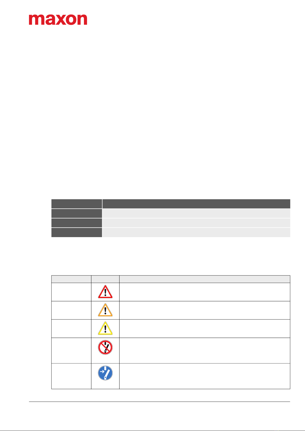
Table 1-2 Symbols and signs
1.1.5 Trademarks and brand names
For easier legibility, registered brand names are listed below and will not be further tagged with their respective trade-
mark. It must be understood that the brands (the list below is not necessarily concluding) are protected by copyright
and/or other intellectual property rights even if their legal trademarks are omitted in the later course of this document.
Table 1-3 Brand names and trademark owners
1.1.6 Copyright
© 2024 maxon. All rights reserved. Any use, in particular reproduction, editing, translation, and copying, without prior
written approval is not permitted (contact: maxon international ltd., Brünigstrasse 220, CH-6072 Sachseln, +41 41 666
15 00, www.maxongroup.com). Infringements will be prosecuted under civil and criminal law. The mentioned trade-
marks belong to their respective owners and are protected under trademark laws. Subject to change without prior
notice.
mmag | «EC frameless DT» Installation Manual | Edition 2024-01 | DocID rel12019
1.2 About the device
The direct drive «EC frameless DT» is a high-performance, high-torque, dynamic brushless DC internal rotor motor
(BLDC motor). It is available in various sizes and is designed to be incorporated into a specially adapted outer body
that serves both as the motor’s supporting structure and as torque-carrying device.
The «EC frameless DT» composes two main parts:
•Stator with electric connections; for installation into a customer-provided outer body (such as housing,
machine structure, or carrier system)
•Magnetic rotor; for on-site assembly with the installed stator and the customer-provided torque-carrying
device
Outer body, motor shaft, and bearings are not part of the «EC frameless DT»’s scope of delivery and are being desig-
ned for a particular case of application by the customer.
Requirement,
Note, Remark
Indicates an activity you must perform prior continuing, or gives information on a
particular item you need to observe.
Best practice Indicates an advice or recommendation on the easiest and best way to further
proceed.
Material
Damage Indicates information particular to possible damage of the equipment.
Brand Name Trademark Owner
DELO-ML® © DELO Industrie Klebstoffe GmbH & Co. KGaA, DE-Windach
EPO-TEK® © Epoxy Technology, Inc., USA-Billerica, MA
Loctite® © Henkel AG & Co. KGaA, DE-Düsseldorf
NORD-LOCK® © Nord-Lock International AB, SE-Malmö
omniFIT® © Henkel AG & Co. KGaA, DE-Düsseldorf
Pico-Clasp © Molex, USA-Lisle, IL
Type Symbol Meaning

General Information
About the safety precautions
«EC frameless DT» Installation Manual
mmag | 2024-01 | rel12019 1-7
Important note on the design
The «EC frameless DT» is a sensorless motor and does not feature any Hall sensor signals. As an option, maxon
offers the «TSX MAG» encoder.
1.3 About the safety precautions
Safety first—always!
BY PRINCIPLE, THE «EC FRAMELESS DT» COMPRISES PARTS THAT PRODUCE STRONG MAGNETIC
FIELDS. IT IS THEREFORE MOST IMPORTANT THAT YOU ARE AWARE OF THE CONSEQUENCES OF THESE
MAGNETIC FORCES, THAT YOU TAKE THE APPROPRIATE PRECAUTIONARY MEASURES, AND THAT YOU
COMMUNICATE THIS FACT TO PERSONS IN YOUR VICINITY!
READ THE FOLLOWING INSTRUCTIONS CAREFULLY BEFORE YOU ENGAGE WITH ANY WORK AND FOL-
LOW THE INSTRUCTIONS GIVEN AT ALL TIMES!
• Make sure that you have read and understood the note “READ THIS FIRST” auf Seite A-2!
• Do not engage with any work unless you possess the stated skills (Kapitel “1.1.2 Target audience” auf
Seite 1-5)!
• Consult Kapitel “1.1.4 Symbols & signs” auf Seite 1-5 to understand the subsequently used indicators!
• You must observe any regulation applicable in the country and/or at the site of implementation with regard to
health and safety/accident prevention and/or environmental protection!
DANGER
High voltage and/or electrical shock
Touching live wires causes death or serious injuries!
• Consider any power cable as connected to live power, unless you have proven the opposite!
• Make sure that neither end of cable is connected to live power!
• Make sure that the power source cannot be engaged while work is in process!
• Obey lock-out/tag-out procedures!
• Make sure to securely lock any power engaging equipment against unintentional engagement and tag it with
your name!
WARNING
Strong magnetic field
High magnetic force can cause serious injuries!
• Keep stator and rotor mechanically blocked at all times! Do so by using a mechanical locking device, a mounting
aid, or non-magnetic spacers!
• Make sure to remove/keep clear any metal parts or metallic items—also such as cardiac pacemakers, implants,
watches, bracelets, credit cards, mobile phones, etc—before you approach the motor!
• Use only non-magnetic tools when you work on the motor or in its vicinity!
• Put up warning signs stating STRONG MAGNETIC FIELDS around the installation area and at the storage loca-
tion!
• Inform persons around of the potential danger. Instruct them accordingly and request them to follow the precau-
tionary measures!

General Information
About the safety precautions
«EC frameless DT» Installation Manual
1-8 mmag | 2024-01 | rel12019
Strong magnetic field
The high magnetic forces produced by the device constitute an imminent hazard to persons wearing a cardiac pace-
maker or metal implants.
All persons who possibly may suffer impairment caused by strong magnetic fields must not approach the device and
must stay clear and in a safe distance of at least two (2) meters.
General rules
• Make sure that all associated devices and components are installed according to local regulations.
• Be aware that, by principle, an electronic apparatus cannot be considered fail-safe. Therefore, you must make sure
that any machine/apparatus has been fitted with independent monitoring and safety equipment. If the machine/
apparatus should break down, if it is operated incorrectly, if the control unit breaks down or if the cables break or get
disconnected, etc., the complete drive system must return—and be kept—in a safe operating mode.
• Be aware that you are not entitled to perform any repair on components supplied by maxon motor.
Electrostatic sensitive device (ESD)
• Wear electrically conductive clothing and footwear.
• Observe ESD protective measures.
WARNING
Pinching and shearing risk
Sudden movement and shift of the rotor can cause serious injuries!
To prevent sudden shift during installation you must keep both stator and rotor blocked at all times. Do so by using
a mechanical locking device, a mounting aid, or non-magnetic spacers!

Specifications
Technical Data
«EC frameless DT» Installation Manual
mmag | 2024-01 | rel12019 2-9
2 SPECIFICATIONS
In its catalog data sheets maxon specifies the motor data with block commutation (according to «Standard Specifica-
tion no. 101», which you can find in the maxon catalog in chapter “Technology short and to the point”. For detailed
information and values consult the data sheets in the Appendix as of page 27.
The motor data listed below refer to field-oriented control (FOC) and therefore differ from the catalog data based on
block commutation. In connection with FOC maxon recommends using the «TSX MAG» encoder module, which can
generate both incremental and commutation signals (Hall signals).
2.1 Technical Data
Parameter DT38S DT38M DT50S DT50M
Key data
[a]
Nominal voltage [b] VDC 21.6 43.2
Nominal speed rpm 9'160 4'690 5'260 3'480
Nominal torque [c] mNm 110 201 352 442
Nominal current A 6.68 6.25 5.98 4.89
Motor constant [d] 38.4 62.3 91.3 123
Winding NTC @ 25 °C K 5 k ±1%, beta (25…85 °C): 3'490
Inputs and
Outputs
(optional) [e]
Incremental and commutation signals H1, H2, H3
2-channel incremental encoder with own NTC
Dimensions
Weight
Rotor g 12 20 28 40
Stator
Other
g
59 84 95 123
Flange 54 65 95 107
Total 113 149 190 230
Overall weight g 125 169 218 270
Ø outside (ØR1) mm 55 72
Ø stator lamination mm 38 50
Ø inside (ØS2) mm 17 28
Length (LM) mm 19 25 22 27
Environment
Ambient temperature °C −40…+100
Humidity % 5…90 (condensation not permitted)
mNm
W
-------------

Specifications
Technical Data
«EC frameless DT» Installation Manual
2-10 mmag | 2024-01 | rel12019
Table 2-4 Technical data (typical)
Parameter DT65S DT65M DT85M DT85L
Key data
[a]
Nominal voltage [b] VDC 43.2
Nominal speed rpm 3440 1930 2'830 1'630
Nominal torque [c] mNm 776 1260 1'900 3'050
Nominal current A 8.43 7.73 15.4 14.1
Motor constant [d] 190 282 364 542
Winding NTC @ 25 °C K 5 k ±1%, beta (25…85 °C): 3'490
Inputs and
Outputs
(optional)
[e]
Incremental and commutation signals
H1, H2, H3
2-channel incremental encoder with own
NTC
Dimensions
Weight
Rotor g 44 71 98 153
Stator
Other
g
182 268 428 621
Flange 151 185 215 266
Total 333 453 643 887
Overall weight g 377 524 741 1'040
Ø outside (ØR1) mm 88 108
Ø stator lamination mm 65 85
Ø inside (ØS2) mm 35.5 47
Length (LM) mm 25 33 33 43
Environment
Ambient temperature °C −40…+100
Humidity % 5…90 (condensation not permitted)
[a] The values refer to field-oriented control (FOC).
[b] The nominal voltage is based on the assumptive supply voltage of 24 or 48 VDC for a positioning controller
with a maximum output voltage of 90% of the supply voltage (0.9 x VCC).
[c] If the stator is mounted in a metallic, thermally conductive housing, heat transfer is usually improved (typically
by 50%) and operation with higher nominal torques is possible.
[d] The motor constant indicates the electrodynamic torque (without friction, etc.), which occurs with current heat
losses of 1 W. It is an important parameter for the strength of a motor.
[e] Choice between multiple functions.
mNm
W
-------------

Specifications
Dimensional Drawings
«EC frameless DT» Installation Manual
mmag | 2024-01 | rel12019 2-11
2.2 Dimensional Drawings
For dimensional drawings see Appendix as of page 27.
2.3 Nameplate
Figure 2-1 Nameplate (typical) – EC frameless DT without (left) and with TSX MAG encoder (right)
Table 2-5 Labeling details
2.4 Standards
The described device has been successfully tested for compliance with the below listed standards.
Table 2-6 Standards
Part ABC
Stator
Manufacturer
Origin
Type
Data Matrix Code
Production data
Production ID and consec. #
Data Matrix Code
Production data
Production ID and consec. #
Part DPart E
Rotor
Data Matrix Code
Production data
Production ID and consec. #
Rotor with
pilot rotor
Data Matrix Code
Production data
Production ID and consec. #
Standards & Specifications
Manufacturing 101 Standard Specification for maxon EC motor

Specifications
Standards
«EC frameless DT» Installation Manual
2-12 mmag | 2024-01 | rel12019
• • p a g e i n t e n t i o n a l l y l e f t b l a n k • •

Installation
«EC frameless DT» Installation Manual
mmag | 2024-01 | rel12019 3-13
3 INSTALLATION
The motor’s two main components—stator with electric connections and magnetic rotor—come in unmounted condi-
tion in packaged cases.
Precautions with multiple packaging
Depending on the order volume, several rotors are supplied in the same packaging.
When removing a rotor, you must ensure that the rotors remaining in the packaging are and remain fixed. Otherwise,
they may attract each other magnetically and thus be damaged.
Motor versions with encoder (with optional «TSX MAG») have an additional pilot rotor equipped to the rotor and the
stator carries a built-in encoder module. The four components are paired with each other during the manufacturing
process and thus form a final unit. It is therefore important that you handle and install the rotor and stator paired.
For motor versions without encoder, rotor and stator are not paired.
Important note on the design
The components for motor versions with encoder are matched and paired with each other. Install them in the paired
state.
BESIDES SPECIAL PRECAUTIONS IN RESPECT TO HEALTH AND SAFETY, THE «EC FRAMELESS DT» MUST
BE INSTALLED IN A PARTICULAR AND SPECIFIC WAY. FOR BOTH SAFE AND EASY INSTALLATION AS
WELL AS RELIABLE OPERATION CLOSELY FOLLOW THE BELOW DESCRIBED INFORMATION IN GIVEN
ORDER.
Figure 3-2 Main components
1 Stator 3 Pilot rotor (only in connection with TSX MAG)
2 Rotor 4 TSX MAG encoder (optional)

Installation
General Rules
«EC frameless DT» Installation Manual
3-14 mmag | 2024-01 | rel12019
3.1 General Rules
Check on the safety matters and rules (
page 7) before you proceed.
BY PRINCIPLE, THE «EC FRAMELESS DT» COMPRISES PARTS THAT PRODUCE STRONG MAGNETIC
FIELDS. IT IS THEREFORE MOST IMPORTANT THAT YOU ARE AWARE OF THE CONSEQUENCES OF THESE
MAGNETIC FORCES, THAT YOU TAKE THE APPROPRIATE PRECAUTIONARY MEASURES, AND THAT YOU
COMMUNICATE THIS FACT TO PERSONS IN YOUR VICINITY!
BEFORE YOU ENGAGE WITH ANY WORK, READ, UNDERSTAND, AND FOLLOW THE SAFETY PRECAU-
TIONS AS OF PAGE 7!
OBSERVE THE FOLLOWING NOTICE ON THE PREREQUISITES FOR PERMISSION TO COMMENCE INSTAL-
LATION.
The «EC frameless DT» is considered as partly completed machinery according to EU Directive 2006/42/EC, Article
2, Clause (g) and is intended to be incorporated into or assembled with other machinery or other partly com-
pleted machinery or equipment.
Electrostatic Sensitive Devices (ESD)
• Wear electrically conductive clothing and footwear.
• Observe ESD protective measures.
Requirements for operation
The function of the drive is only guaranteed if all specified design characteristics and tolerances are met. Do only con-
tinue if this is actually the case. If this is not the case you must rectify the deviations, first.
Safe, trouble-free, long-term operation is only possible…
• if the defined properties of the outer body (such as housing, machine structure, or carrier system) as well as the
motor shaft and its bearings are met, and
• if centering and axial position of stator and rotor are carried out with sufficient accuracy!
Possible irreversible damage of motor
Until completion of the installation, individual components can be permanently damaged by improper handling.
• Handle the components with particular care.
• Pay special attention to cleanliness.
• Make sure that no impurities, foreign objects, or particles penetrate the drive or can be attracted by the motor mag-
nets.
WARNING
Risk of injury
Operating the device without the full compliance of the surrounding system with the EU Directive 2006/42/
EC may cause serious injuries!
• Do not operate the device, unless you have made completely sure that the other machinery fully complies with
the EU directive’s requirements!
• Do not operate the device, unless the other machinery fulfills all relevant health and safety aspects!
• Do not operate the device, unless all respective interfaces have been established and fulfill the requirements
stated in this document!
WARNING
Pinching and shearing risk
Sudden movement and shift of the rotor can cause serious injuries!
To prevent sudden shift during installation you must keep stator and rotor blocked at all times. Do so by using a
mechanical locking device, a mounting aid, or non-magnetic spacers!

Installation
Design Guidelines
«EC frameless DT» Installation Manual
mmag | 2024-01 | rel12019 3-15
Thermal behavior
The values given in the data sheet for nominal torque (maximal continuous torque), thermal resistances, and nominal
current (maximal continuous current) refer to the motor mounted to a plastic plate with limited heat dissipation capability
and free convection.
When mounted to a metal flange, the thermal resistance Rth2 can be reduced by up to 80%. Thus, technical measures
(such as good ventilation, heat-conducting metallic mounts, or heat sinks) can substantially reduce temperatures and
significantly increase performance.
3.2 Design Guidelines
Important note on the design
The correct technical design of the bearing arrangement and the integration into the application’s housing are the sole
responsibility of the customer.
• maxon does not make any suggestions as to how a customer-side integration into the respective application must be
designed and laid out or what it should look like.
• The points listed below are intended to serve as an aid and to show (in a non-exhaustive manner) which drive-side
aspects need to be taken into account in a customer-built design.
• The points listed below do not claim to be complete.
3.2.1 Geometric Tolerances
The dimensional drawings (see Appendix as of page 27) show the shape and position tolerances of stator to rotor.
Other tolerances may apply to specific motor designs, which will be communicated by appropriate means.
Compliance with the designated tolerances is vital and guarantees that the motor achieves the specified performance
data (such as torque and speed). Even minor deviations from the specified form and position tolerances will result in a
reduction of the performance data. Exceeding deviations can lead to stripping of the rotor, to an increased cogging tor-
que, and to permanent damage to the motor.
maxon therefore urgently recommends that the specified form and position tolerances indicated in the dimensional dra-
wings be observed.
3.2.2 Mechanical Design
The customer's components (for example housing and shaft) must be designed for the expected mechanical loads and
forces in terms of strength, rigidity, and stability.
3.2.3 Magnetic Forces
The rotor of the «EC frameless DT» is equipped with strong magnets. As a result, large forces can occur in both the axial
and radial directions. Note this in particular with regard to the following topics:
• Bearing arrangement
• Calculations for strength and stiffness
• Joining the individual components during assembly
• Maintenance
• Dismantling and deconstruction
With rotor and stator arranged in accordance to the specifications on the dimensional drawings (see Seite 2-11), then
the axial and radial forces emanating from the magnetic field are minimal.
3.2.4 Heat Dissipation
The stator of the «EC frameless DT» must be thermally well connected to the customer’s housing. This can be achieved
by the design and material selection of the housing and via suitable fit tolerances.

Installation
Design Guidelines
«EC frameless DT» Installation Manual
3-16 mmag | 2024-01 | rel12019
3.2.5 Bearing and Fixation of the Rotor
maxon recommends the use of ball bearings with an ISO tolerance class P5 or higher.
maxon recommends to join the rotor of the «EC frameless DT» and the customer’s counterpart (shaft) by adhesive
bonding. It is important to ensure that the bonded joint is designed that the maximum motor torque can be transmitted
with a sufficient safety margin over the entire operating range.
Possible irreversible damage of motor
The rotor is not designed to produce a force-fit torque transmission to the customer shaft by means of a press fit (inter-
ference fit, shrink fit).
maxon explicitly advises against a press fit.
The following data are to be understood as recommendations. They apply to common models and methods under
typical conditions and do not claim to be complete or correct. For manufacturers and sources of supply see page 6.
Table 3-7 Fixation of the rotor – recommended adhesives
3.2.6 Fixation of the Stator
maxon recommends to fix the stator of the «EC frameless DT» axially using bolted connections. This axial screw con-
nection also serves as a non-positive transmission of the torque.
Requirements for operation
Use only screws that, once installed, do not protrude the inside front face of the stator flange. Too long screws can
damage the printed circuit board, thus possibly causing electrical breakdown and destruction of the motor.
The following data are to be understood as recommendations. They provide an overview of the recommended faste-
ning screws and the minimum tightening torques for safe torque transmission. An application-specific screw calcula-
tion as to VDI guideline 2230 must be taken into account.
The screw connections must be tightened to the appropriate torque using a torque wrench.
Table 3-8 Fixation of the stator – recommended bolted joints
Drive Shaft material Adhesive Shaft tolerance Surface finish
EC frameless DT38S Steel Ergo 4430
DELO-ML 5327 17 f7 Ra 1.6
EC frameless DT38M
EC frameless DT50S Steel Ergo 4430
DELO-ML 5327 28 f7 Ra 1.6
EC frameless DT50M
EC frameless DT65S Steel Ergo 4430
DELO-ML 5327 35.5 f7 Ra 1.6
EC frameless DT65M
EC frameless DT85M Steel Ergo 4430
DELO-ML 5327 47 f7 Ra 1.6
EC frameless DT85L
Drive Screws Property class Tightening torque
EC frameless DT38S 3 x M3 min A2-80 / 6.8 1 Nm ±0.2
EC frameless DT38M
EC frameless DT50S 4 x M4 min A2-80 / 6.8 2.5 Nm ±0.5
EC frameless DT50M
EC frameless DT65S 4 x M4 min A2-80 / 6.8 2.5 Nm ±0.5
EC frameless DT65M
EC frameless DT85M 4 x M4 min A2-80 / 6.8 2.5 Nm ±0.5
EC frameless DT85L

Installation
Mechanical Installation
«EC frameless DT» Installation Manual
mmag | 2024-01 | rel12019 3-17
The screw connections must locked and secured using threadlocker or Nord-Lock safety washers. For manufacturers
and sources of supply see page 6.
Table 3-9 Fixation of the stator – recommended screw locks
3.2.7 Tools & Equipment
• Hand tools, non-magnetic
• Cleaning agent
• Lint-free cloths
• Centering aids for rotor and stator, non-magnetic
• Mounting fixture (for example hand-lever press or drill stand)
3.3 Mechanical Installation
Recommended procedure
The installation approach that matches your case of application depends on your setup, your actual application
design, and your specific mounting conditions.
Observe the recommendations and analogously adjust the procedure as to your case of application.
Protect hands and fingers
Put on well-fitting, cut-resistant protective gloves.
Two variants of mounting options are schematically shown below, which must be understood as a general guide. The
actual conditions depend on the respective customer application.
For easier differentiation, color coding is used in illustrations of individual components are shown:
1) Fasten rotor on shaft
Material pair
or
Combination of parts
Product Remark
Steel screw / Aluminum casing
Steel screw / Steel casing
DELO-ML 5327 [g]
EPO-TEK 301-2G [g]
Loctite 222 [f]
Nord-Lock [f]
omniFIT 230L [f]
[f] detachable connection [g] inseparable, rigid connection
WARNING
Pinching and shearing risk
Sudden movement and shift of the rotor can cause serious injuries!
To prevent sudden shift during installation you must keep stator and rotor blocked at all times. Do so by using a
mechanical locking device, a mounting aid, or non-magnetic spacers!
Stator of the «EC frameless DT» Housing (by customer)
Rotor of the «EC frameless DT» Shaft (by customer)

Installation
Mechanical Installation
«EC frameless DT» Installation Manual
3-18 mmag | 2024-01 | rel12019
Figure 3-3 Mounting the rotor
2) Position and align the shaft with the housing. Support the shaft.
Figure 3-4 Positioning shaft and housing
3) Mount and fasten stator in a guided and controlled position.
Figure 3-5 Mounting the stator
4) Check installation position of rotor and stator as to dimensional drawing’s specifications (as of page 27).
Figure 3-6 Checking the installation position

Installation
Electrical Installation
«EC frameless DT» Installation Manual
mmag | 2024-01 | rel12019 3-19
3.4 Electrical Installation
Electrical Interface—possible permanent damage
• Handle connections and cables with special care!
• Do not kink cable, do not bend around small radii, do not route around sharp edges!
• Do not apply tensile stress, use strain relief!
3.4.1 Connections
3.4.1.1 Motor
By default, the «EC frameless DT» is supplied without connector. It has three individual strands to connect to the
motor windings 1, 2, and 3 as well as two additional individual strands for the NTC thermistor.
Figure 3-7 Motor connections
Table 3-10 Terminal assignment – Motor strands
Color Signal Description
red [h] W1 Motor winding 1
black [h] W2 Motor winding 2
white [h] W3 Motor winding 3
violet [i] NTC_IN Thermistor
blue [i] NTC_OUT Thermistor
[h] AWG24 for DT38, AWG18 for DT50 & DT65
and AWG16 for DT85
[i] AWG18 for all sizes

Installation
Electrical Installation
«EC frameless DT» Installation Manual
3-20 mmag | 2024-01 | rel12019
3.4.2 Temperature Monitoring
3.4.2.1 Motor: Temperature Sensor
The «EC frameless DT» is equipped with two in parallel connected temperature sensors based on the NTC thermistor
principle (NTC; Negative Temperature Coefficient). The data sheet (as of page 27) shows the equivalent resistance
of this parallel circuit. Thereby, a negative temperature coefficient is used, which is associated with a decreasing elec-
trical resistance as the temperature increases.
The NTC thermistor are each positioned between two motor windings. The direct coupling to the winding results in a
delay-free and very accurate temperature measurement. This leads to a minimal delay of the temperature measure-
ment and to a higher thermal resistance (lower measured temperature). For this reason, temperature monitoring is pri-
marily suitable for continuous operation, whereby the actual temperature measurement depends on the mounting con-
ditions and requires testing.
The NTC thermistor does not perform linear. The respective temperature can be calculated using the following para-
meters (find the corresponding values in the data sheet; Appendix as of page 27):
Motionless, permanently energized motor
If the rotor does not turn while the same winding is permanently energized, no uniform heating takes place in the
motor. In this case, the formula can only serve as an approximation.
Constant (temperature coefficient) optimized for the operating
range of the motor
Nominal resistance at standard temperature
Standard temperature of 25 °C (298.15 K)
T R 1
R
R25
--------
ln
beta
------------------- 1
T25
--------
+
----------------------------------- K =
T25 298.15 K =
beta
R25 T25
T25
Other manuals for EC frameless DT
1
Table of contents