Maxxtools 21058 User manual

GEBRUIKSHANDLEIDING
INSTRUCTION MANUAL
NL: Compressor lucht gekoeld
EN: Air Compressor
COMPRESSOR
Model: 21058 - 21059


(NL) HANDLEIDING
GELUIDSARME OLIEVRIJE LUCHTCOMPRESSOR
Lees deze instructies zorgvuldig door voordat u probeert het beschreven product te monteren,
installeren, bedienen of onderhouden. Bescherm uzelf en andere mensen door alle veiligheidsin-
formatie in acht te nemen. Het niet naleven van instructies kan leiden tot persoonlijk letsel en / of
materiële schade! Bewaar instructies voor toekomstige referentie.
BESCHRIJVING
Directe aandrijving, stilte Olievrije luchtcompressoren zijn ontworpen voor de doe-het-zelfmarkt met
een verscheidenheid aan thuis- en autowerk. Deze compressoren kunnen spuitpistolen, slagmoer-
sleutels, schiethamers en ander gereedschap aandrijven. Nat en schoon Perslucht (<8 bar) kan
worden geleverd door deze compressor. Installeer een waterlter of luchtdroger tussen compressor
en elektrisch gereedschap als het elektrisch gereedschap droge lucht nodig heeft.
VEILIGHEIDSRICHTLIJNEN
Deze handleiding bevat zeer belangrijke informatie die u moet lezen en begrijpen. Deze informatie
wordt verstrekt voor VEILIGHEID en om APPARATUURPROBLEMEN TE VOORKOMEN.
De volgende symbolen helpen om deze informatie te begrijpen.
▲ GEVAAR! Gevaar duidt op een op handen zijnde gevaarlijke situatie die, indien deze niet wordt
vermeden, de dood of ernstig letsel tot gevolg zal hebben.
▲ WAARSCHUWING! Waarschuwing geeft een mogelijk gevaarlijke situatie aan die, als deze niet
wordt vermeden, kan leiden tot ernstig of dodelijk letsel.
▲ LET OP! Voorzichtigheid duidt op een gevaarlijke situatie die, indien niet vermeden, KAN
resulteren in licht of matig letsel.
▲ NOTA Kennisgeving geeft belangrijke informatie aan dat, indien niet opgevolgd, de apparatuur
KAN beschadigen.
Uitpakken
Controleer voor en na het uitpakken van de verpakking zorgvuldig op eventuele schade die
tijdens het transport is opgetreden. Zorg ervoor dat de ttingen, bouten en dergelijke goed vast
zitten voordat u de compressor in gebruik neemt.
▲ WAARSCHUWING! Gebruik de compressor niet als deze is beschadigd.
Deze schade kan barsten veroorzaken en letsel of materiële schade veroorzaken.
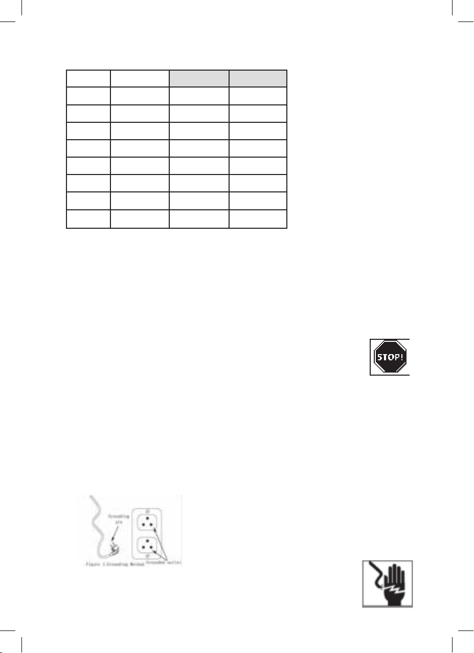
▲ GEVAAR! Ademluchtwaarschuwing
Deze compressor is niet uitgerust en mag niet worden gebruikt “zoals het is” om lucht van
ademkwaliteit te leveren. Voor elke toepassing van lucht voor menselijke consumptie moet
de luchtcompressor worden uitgerust met geschikte inline veiligheids- en alarmapparatuur.
Deze extra apparatuur is nodig om de lucht goed te lteren en te zuiveren om te voldoen aan
minimale specicaties voor lokale standaard.
ALGEMENE VEILIGHEIDSINFORMATIE
Aangezien de luchtcompressor en andere componenten (materiaalpomp, spuitpistolen, lters,
smeerunits, slangen, etc.) een hogedrukpompsysteem vormen, moeten de volgende veiligheids-
maatregelen te allen tijde in acht worden genomen:
1. Lees alle handleidingen die bij dit product zijn geleverd. Zorg dat u goed bekend
bent met de bedieningselementen en het juiste gebruik van de apparatuur.
2. Volg alle lokale elektrische en veiligheidscodes zoals in de VS, de National
Electrical Codes (NEC) en de Occupational Safety and Health Act (OSHA).
3. Alleen personen die goed bekend zijn zijn met deze regels voor veilig gebruik
mogen de compressor gebruiken.
4. Houd bezoekers weg en sta NOOIT kinderen toe in het werkgebied.
5. Draag een veiligheidsbril wanneer u de pomp van de unit bedient.
6. Ga niet op de pomp staan of gebruik deze niet als houvast.
7. Inspecteer voor elk gebruik het persluchtsysteem en de elektrische componenten op tekenen
van schade, verslechtering, zwakte of lekkage. Repareer of vervang defecte items voor gebruik.
8. Controleer regelmatig of alle bevestigingen goed vast zitten.

▲ WAARSCHUWING! Motoren, elektrische apparatuur en bedieningselementen
kunnen elektrische bogen veroorzaken die een ontvlambaar gas of damp doen
ontvlammen. Gebruik of repareer nooit in of nabij een brandbaar gas of damp.
Bewaar nooit ontvlambare vloeistoffen of gassen in de buurt van de compressor.
▲ LET OP! Compressoronderdelen kunnen heet zijn, zelfs als de unit is gestopt.
9. Houd uw vingers uit de buurt van een draaiende compressor, snel bewegende
en hete onderdelen kunnen letsel en / of brandwonden veroorzaken.
10. Als de apparatuur abnormaal begint te trillen, STOPT u de motor / motor en
controleert u onmiddellijk de oorzaak. Trilling is over het algemeen een
waarschuwing voor problemen.
11. Houd de buitenkant van de motor / motor vrij van olie, oplosmiddel of overmatig
vet om brandgevaar te vermijden.
▲ WAARSCHUWING! Verwijder of probeer nooit de veiligheidsklep af te stellen.
Houd de veiligheidsklep vrij van verf en andere ophopingen.
▲ GEVAAR! Probeer nooit een tank te repareren of te wijzigen! Lassen, boren of
andere aanpassingen zullen de tank verzwakken, wat kan leiden tot schade
door breuk of explosie. Vervang altijd versleten of beschadigde tanks.
▲ WAARSCHUWING! Tap dagelijks vloeistof uit de tank af.
13. Tanks roesten door vochtophoping, wat de tank verzwakt. Zorg ervoor dat de tank
regelmatig leegloopt en periodiek inspecteert op onveilige omstandigheden zoals
roestvorming en corrosie.
14. Snel bewegende lucht zal stof en vuil doen opwaaien, wat schadelijk kan zijn.
Laat de lucht langzaam ontsnappen bij het aftappen van vocht of het drukloos
maken van het compressor-systeem.
VOORZORGSMAATREGELEN
▲ WAARSCHUWING!
Spuit geen brandbare materialen in de buurt van open vuur of in de buurt van
ontstekingsbronnen, waaronder de compressoreenheid.
15. Rook niet tijdens het spuiten van verf, insecticiden of andere ontvlambare stoffen.
16. Gebruik bij het spuiten een gezichtsmasker / gasmasker en spuit in een goed
geventileerde ruimte om gezondheid en brandgevaar te voorkomen.
17. Richt geen verf of spuit geen ander gespoten materiaal op de compressor.
Plaats de compressor zo ver mogelijk van het spuitgebied om de opeenhoping
van overspray op de compressor te minimaliseren.
18. Om brandgevaar te verminderen, plaats de compressor ver weg van de
houtsnijder om te voorkomen dat zaagsel in de motor wordt gezogen.
19. Volg de instructies van de fabrikant van de chemicaliën bij het spuiten of
reinigen met oplosmiddelen of giftige chemicaliën.
MONTAGE
MONTAGE VAN WIEL- EN RUBBERVOETEN
Plaats voor gebruik de bout en ring op de tank om de wielen en rubberen voetjes in de doos
vast te zetten, ook om de machine op een horizontale lijn te houden, zie afbeelding 1.
Figuur 1:
MONTAGE LUCHTFILTER
Verwijder de transportplug en vervang deze door het luchtlter dat in de doos is geleverd,
zie afbeelding 2.
Figuur 2:
:
▲
▲
▲

BELANGRIJKSTE TECHNISCHE GEGEVENS
Model 21058 21059
Power 1.5HP 2.0HP 3.5HP
Volt. 230~240 230~240 230~240
Freq. 50Hz 50Hz 50Hz
Speed 2850r/min 2850r/min 2850r/min
Displace. 190L/min 240L/min 480L/min
Pressure 0.8Mpa 0.8Mpa 0.8Mpa
Noise 85dBa 85dBa 86dBa
NW 22kg 24 kg 45 kg
INSTALLATIE
Het is uiterst belangrijk om de compressor te installeren in een schone, goed geventileerde ruimte
waar de omgevingsluchttemperatuur niet hoger zal zijn dan 40 ° C.
Een minimum afstand van 1 m tussen de compressor en objecten is vereist omdat objecten de
luchtstroom kunnen belemmeren.
▲ LET OP! Plaats de luchtinlaat van de compressor niet in de buurt van stoom, verfspray,
zandstraalgebieden of andere verontreinigingsbronnen. Dit vuil zal de motor beschadigen.
ELEKTRISCHE INSTALLATIE
▲ WAARSCHUWING! Alle bedrading en elektrische aansluitingen moeten worden uitgevoerd door
eengekwaliceerdeelektricien.Deinstallatiemoetinovereenstemmingzijnmetlokalecodes
en nationale elektrische codes.
▲ LET OP! Gebruik nooit een verlengsnoer voor dit product. Gebruik een extra
luchtslang in plaats van een verlengsnoer om stroomverlies en permanente
motorschadetevoorkomen.Bijgebruikvaneenverlengsnoervervaltdegarantie.
AARDINGSINSTRUCTIES
1. Dit product is bedoeld voor gebruik op een nominaal circuit van 230 volt en heeft een
aardingsstekker die lijkt op de stekker die wordt geïllustreerd in Fig.3. Zorg ervoor dat het
product is aangesloten op een stopcontact met dezelfde conguratie als de stekker. Dit
product moet worden geaard. In het geval van een elektrische kortsluiting vermindert
aarding het risico op elektrische schokken door een ontsnappingsdraad voor elektrische
stroom te bieden. Dit product is uitgerust met een snoer met een aardingsdraad met een
geschikte aardingsdraad met een geschikte aardingsstekker. De stekker moet worden
aangesloten op een stopcontact dat correct is geïnstalleerd en geaard in overeenstemming
met alle lokale codes en verordeningen.
Figuur 3:
▲ GEVAAR! Onjuistgebruikvaneenaardingsstekkerkanleidentot
eenmogelijkrisicoopelektrischeschokken!
▲ GEVAAR! Gebruikbijditproductgeenaardingsadapter!
3
▲
▲
▲

2. Als reparatie of vervanging van het netsnoer of de stekker nodig is, sluit dan geen aarddraad
aan op een van de platte aansluitingen. De draad met isolatie met een groen buitenoppervlak
(met of zonder gele strepen) is de aarddraad.
▲ WAARSCHUWING! Sluit nooit groene (of groene en gele) draad aan op een actieve terminal.
3. Neem contact op met een gekwaliceerde elektricien of onderhoudsmonteur als de aardings
instructies niet volledig worden begrepen of als u twijfelt of het product correct is geaard. Wijzig
de stekkerhouder nooit privé; als er geen passend stopcontact is, laat dan een geschikt
stopcontact installeren door een gekwaliceerde elektricien.
▲ WAARSCHUWING!
1. Lokale codes voor elektrische bedrading verschillen van gebied tot gebied. De bronbedrading,
de stekker en de beschermer moeten geschikt zijn voor ten minste de stroomsterkte en spanning
die op het typeplaatje van de motor zijn aangegeven, en voldoen aan alle elektrische codes
voor dit minimum,
2. Gebruik een trage zekering of een stroomonderbreker.
▲ LET OP! Oververhitting,kortsluitingenbrandschadezullenhetgevolgzijnvanonvoldoende
bedrading, enz.
NOTA: 230 volt, 5 amp units kunnen onder de volgende omstandigheden op een 230 volt circuit
worden gebruikt:
a. Er zijn geen andere elektrische apparaten of lampen aangesloten op hetzelfde vertakte
circuit.
b. Spanningsvoorziening is normaal.
c. Circuit is uitgerust met een stroomonderbreker van 5 ampère of een trage zekering van 15
ampère.
3. Als niet aan deze voorwaarden kan worden voldaan of als de stroombeveiliging wordt
onderbroken, kan het nodig zijn om de compressor te laten werken op 230 volt, 5 ampère
circuits.
OPERATIE
Drukschakelaar - Auto / uit-schakelaar
In de “AUTO” -stand schakelt de compressor automatisch uit wanneer de esdruk de maximale
vooraf ingestelde druk (0,8 Mpa) bereikt en loopt automatisch wanneer de esdruk de
minimale vooraf ingestelde druk bereikt (ongeveer 0,6 Mpa). In de “UIT” -stand zal de compressor
niet werken. Deze schakelaar moet in de “UIT” -stand staan bij het aansluiten of loskoppelen van
het netsnoer van het stopcontact of bij het wisselen van luchtgereedschap.
Regulator
De regelaar wordt gebruikt om de uitlaatdruk aan te passen aan luchtgereedschap.
Veiligheidsklep
Het geeft automatisch perslucht vrij wanneer de druk in de tank hoger is dan de toegestane druk.
Afvoerleiding
Afvoerleiding verbindt pompkop en terugslagklep. Het is heet als de compressor draait. Raak nooit
de afvoerleiding aan om ernstige brandwonden te voorkomen.
Terugslagklep
Terugslagklep is een eenrichtingsklep waardoor perslucht naar de tank kan gaan, maar voorkomt
dat perslucht in de tank terug naar de pomp gaat.
Handgreep en wielen
Ontworpen om de compressor gemakkelijk te verplaatsen.
▲ WAARSCHUWING! Gebruik de handgreep nooit op units met wielen om de unit volledig van de
grond te tillen.
Afvoerklep
Deze klep bevindt zich aan de onderkant van de tank. gebruikt om water uit de tank af te voeren.
Zorg ervoor dat de meterdruk van de tank lager is dan 1 bar, open de afvoerklep om het water uit
de tank te laten ontsnappen en sluit deze stevig. Deze actie moet elke week worden uitgevoerd.
Figuur 4:
▲
▲
▲
▲
▲
▲
gauge
is
the
aust
close
tion
e every
Figure 4:

INBRAAKPROCEDURE
▲ LET OP! Bevestig de luchtklem of ander gereedschap pas op de uitlaat als de unit is
gecontroleerd en de startprocedure is voltooid.
BELANGRIJK: Gebruik de compressor niet voordat u de instructies heeft gelezen, anders kan
er schade ontstaan.
1. Draai de regelaar helemaal rechtsom om de luchtstroom te openen.
2. Zet de schakelaar in de UIT-stand en steek de stekker in het stopcontact.
3. Zet de schakelaar in de stand AUTO en laat de unit 30 minuten draaien om de pomp-
onderdelen te laten draaien.
4. Draai de regelknop volledig linksom. De compressor bouwt op tot de maximale vooraf
ingestelde druk en wordt uitgeschakeld.
Figuur 5:
5. Draai de regelknop rechtsom om lucht te laten ontsnappen. De compressor start opnieuw op
bij een vooraf ingestelde druk (ongeveer 6 bar).
6. Draai de regelknop tegen de klok in om de lucht uit te schakelen en zet de schakelaar in de
uit-stand.
7. Bevestig de boorkop of ander gereedschap aan de buitenkant. Open de drukschakelaar
naar AUTO positie, de compressor begint te werken en pompt lucht in de tank. Het schakelt
automatisch uit wanneer het apparaat de maximale vooraf ingestelde druk bereikt. In de
UIT-stand kan de drukschakelaar niet werken en zal de compressor niet werken. Zorg ervoor
dat de schakelaar in de UIT-stand staat wanneer u het netsnoer aansluit of loskoppelt op een
stopcontact.
VOCHT IN PERSLUCHT.
Vocht in de lucht verandert in water wanneer lucht wordt samengeperst of de temperatuur
daalt. Als de luchtvochtigheid hoog is of als een compressor lange tijd continu wordt gebruikt,
verzamelt zich water in de tank. Als u een verfspuit of zandstraalpistool gebruikt, wordt vocht
uit de tank via de slang en uit het pistool gevoerd als water vermengd met het spuitmateriaal.
BELANGRIJK: Deze condensatie veroorzaakt watervlekken in een verfbeurt, vooral bij het
spuiten anders dan verf op waterbasis. Bij zandstralen zorgt dit ervoor dat het zand vast komt
te zitten en het pistool verstopt waardoor het niet meer werkt. Een droog lter in de luchtleiding,
zo dicht mogelijk bij het pistool, helpt dit vocht te verwijderen.
VEILIGHEIDSKLEP
▲ WAARSCHUWING! Verwijderofprobeerdeveiligheidsklepnietaftestellen!
De veiligheidsklep moet af en toe onder druk worden gecontroleerd door met de hand aan de
ring te trekken. Als er lucht lekt nadat de ring is losgelaten of als de klep vastzit en niet kan worden
bediend met de ring, MOET deze worden vervangen.
REGELAAR (guur 6)
1. De regelaar past de luchtdruk aan op
een luchtaangedreven gereedschap of
verfspuitpistool.
2. Pas de uitlaatluchtdruk aan door aan
de knop te draaien zoals in Afb. 6.
▲
▲
▲
Figuur 6:
▲
f
e
or
f
et
▲
▲

DRUK METER
Er zijn 1 of 2 meters op dit type compressor, één toont de druk in de tank en een
andere (als er 2 meters zijn) toont de uitlaatdruk na de regelaar.
ONDERHOUD
▲ WAARSCHUWING! Ontkoppel de stroombron en laat vervolgens alle druk van
het systeem af voordat u probeert te installeren, service te verlenen, te verplaatsen
of onderhoud uit te voeren.
Controleer de compressor vaak op zichtbare problemen en volg de onderhoudsprocedures
telkens wanneer de compressor wordt gebruikt.
1. Trek aan de veiligheidsklep en laat deze terugklikken naar de normale positie.
▲ WAARSCHUWING! De veiligheidsklep moet worden vervangen als deze niet kan worden
bediend of als er lucht lekt nadat de ring is losgelaten.
2. Schakel de compressor uit en laat de druk van het systeem af. Tap het vocht af uit de tank door
de aftapkraan onder de tank te openen.
3. Verwijder stof en vuil van motor, tank en luchtvaartmaatschappijen en pomp koelribben terwijl
de compressor nog UIT staat.
BELANGRIJK: Plaats het apparaat zo ver mogelijk van het spuitgebied, aangezien de slang
ervoor zorgt dat overspray het lter niet verstopt.
SMERING
SAE30-olie wordt aanbevolen te gebruiken. Houd het oliepeil in de rode cyclus van olieglas.
THERMISCHE OVERBELASTINGBESCHERMING
▲LET OP! Deze compressor is uitgerust met een automatische reset thermische overbelastings-
beveiliging, die de motor uitschakelt als deze oververhit raakt.
Als de thermische overbelastingsbeveiliging de motor vaak uitschakelt, zoek dan naar de
volgende oorzaken.
1. Laagspanning.
2. Verstopt luchtlter.
3. Gebrek aan goede ventilatie.
▲ LET OP! Als de thermische overbelastingsbeveiliging wordt geactiveerd, moet de motor eerst
kunnenafkoelenvoordatopstartenmogelijkis.Demotorstartautomatischzonderwaarschuwing
opnieuw als deze op het stopcontact is aangesloten en het apparaat is ingeschakeld.
OPSLAG
1. Bewaar de slang en de compressor op een koele, droge plaats wanneer ze niet worden
gebruikt.
2. Uitlaatwater uit tank.
3. Koppel de slang los en hang deze bovenop de compressor om schade te voorkomen.

PROBLEEMOPLOSSINGSTABEL
SYMPTOOM MOGELIJKE OORZAKEN OPLOSSING
Compressor kan niet
starten / herstarten
Motor slaat af of loopt
langzaam
Zekeringen springen uit /
stroomonderbrekers vallen
herhaaldelijk uit
VOORZICHTIGHEID!
Gebruik nooit een verleng-
snoerbijditproduct.
De thermische overbelas-
tingsbeveiliging schakelt
herhaaldelijk uit
1. Geen elektrische
voeding, losse draad-
connector.
2. Zekering uitgeschakeld.
3. Stroomonderbreking.
4. Thermische overbelas-
tingsschakelaar open.
5. Drukschakelaar werkt
niet.
1. Spanning is te laag.
2. Laag stroomverbruik
door slechte verbinding.
3. Kortsluiting in de motor
4. Terugslagklep is geblok-
keerd.
1. Onjuiste zekering, circuit
overbelast.
2. Defecte terugslagklep
of onbelast.
1. Laagspanning.
2. Verstopt luchtlter.
3. Gebrek aan goede
ventilatie / kamertem-
peratuur te hoog.
4. Controleer klepstoring.
5. Compressorkleppen
zijn defect.
1. Zorg ervoor dat de machine
is aangesloten op de voeding,
controleer de connector en de
motoroverbelastingsschakelaar.
2. Vervang zekering.
3. Reset de stroomonderbreker,
controleer op de laagspannings-
omstandigheden.
4. Schakel de luchtcompressor uit,
wacht tot de motor is afgekoeld
en sluit de overbelastingsscha-
kelaar en laat hem dan weer
draaien.
5. Vervang de drukschakelaar.
1. Controleer de laagspannings-
condities.
2. Controleer de connectoren,
elimineer de verlengkurk indien
gebruikt, controleer het circuit
met de voltmeter.
3. Vervang de motor. Zoek een
gecerticeerde elektricien,
controleer de motor en bedra-
ding. Ga verder met zijn of haar
aanbevelingen.
4. Demonteer de terugslagklep
om te controleren of deze is
geblokkeerd en vervang deze.
GEVAAR!Demonteerdeterugslag-
klep nooit onder druk. Ledig eerst
de tank.
1. Controleer op juiste zekering,
gebruik een tijdvertragende
zekering.
Koppel andere elektrische
apparaten los van het circuit
van bedien de compressor op
zijn eigen aftakcircuit.
2. Vervangen of repareren.
GEVAAR!Demonteerdeterugslag-
klep nooit onder druk. Ledig eerst
de tank.
1. Verwijder het verlengsnoer,
controleer dit met een voltmeter.
2. Reinig lter (zie het hoofdstuk
Onderhoud).
3. Verplaats de compressor naar
een goed geventileerde ruimte.
4. Vervangen.
5. Vervang de klepconstructie.
GEVAAR!Demonteerdeterugslag-
klep nooit onder druk. Ledig eerst
de tank

PROBLEEMOPLOSSINGSTABEL
SYMPTOOM MOGELIJKE OORZAKEN OPLOSSING
Stoten, rammelen,
overmatige trilling
De TANKDRUK daalt
wanneer de compressor
wordt uitgeschakeld
Compressor draait continu
en de luchtopbrengst is
lager dan normaal / lage
persdruk
Overmatig vocht in
afvoerlucht
Compressor draait continu
en veiligheidsklep opent
als de druk stijgt
Overmatig starten en stop-
pen (automatisch starten)
Er lekt lucht uit de ontlast-
klep op de drukschakelaar
1. Losse bouten, tank staat
niet op een horizontale
lijn.
2. Defect lager op excen-
trische of motoras.
3. De cilinder of piston
heeft inkervingen.
1. Losse aftapkraan.
2. Controleer klep lekt.
3. Losse aansluitingen bij
drukschakelaar of
regelaar.
1. Overmatig luchtverbruik,
compressor te klein.
2. Verstopt inlaatlter.
3. Luchtlekkage in leidin-
gen (op machine of in
buitensysteem).
4. Gebroken inlaatkleppen
5. Zuigerveer versleten.
1. Overmatig water in de
tank.
2. Hoge luchtvochtigheid.
1. Defecte drukschakelaar.
2. Defecte veiligheidsklep.
Overmatige condensatie
in tank.
Terugslagklep zit vast in
open positie.
1. Draai de bouten vast, verplaats
de tank op een horizontale lijn.
2. Vervangen.
3. Vervang of repareer indien
nodig.
1. Draai vast.
2. Demonteer de keerklep, reinig
of vervang.
3. Controleer alle verbindingen
met zeep en wateroplossing
en draai ze vast.
1. Verminder het gebruik of koop
een eenheid met een hogere
luchttoevoer (SCFM).
2. Maak schoon of vervang.
3. Vervang lekkende onderdelen
of zet ze indien nodig vast.
4. Vervang de compressorkleppen.
5. Vervang de zuiger en cilinder.
1. Laat de tank na elk gebruik
leeglopen.
2. Ga naar een gebied met minder
vochtigheid; Tap de luchttank
vaker af bij vochtig weer en
gebruik een luchtleidinglter.
OPMERKING: Watercondensatie
wordt niet veroorzaakt door een
storing in de compressor.
1. Vervang schakelaar.
2. Vervang de veiligheidsklep
door een origineel vervangings-
onderdeel.
Laat vaker uitlekken.
Verwijder en vervang de terugslag-
klep.
GEVAAR!Demonteerdeterugslag-
klep nooit onder druk. Ledig eerst
de tank.

DIAGRAM
8
Exploded Drawing (DOF1100-24)

ONDERDELEN
NO PART UNIT QTY NO PART UNIT QTY
1 Afdekking ventilator PC 4 22 Capasiteitsafdekking PC 2
2 Ventilator a PC 2 23 Capasiteitsmeter PC 2
3 Vliegwiel PC 4 24 Pakking van de buis PC 2
4 Lager 6006-2Rs PC 4 25 Afvoerbuis SET 1
5 Drijfstang PC 4 26 Rubbere schroef PC 4
6 Piston ring PC 4 27 Schroef M6 PC 4
7 Piston Cover PC 4 28 50 Liter tank(geverfd) PC 1
8 Cylinder PC 4 29 Wiemontageset SET 2
9 Klepafdichting PC 4 30 Electromagneetklep SET 1
10 Klepplaat PC 4 31 Eenrichtingsklep 3/8 PC 1
11 Cylinder hoofddichting PC 4 32 Afvoerklep SET 1
12 Luchtlter 1/4 PC 2 33 Rubbere voet SET 2
13 Cylinder kop PC 4 34 Netsnoer SET 1
14 Verbindingsbuis PC 4 35 Veiligheidsklep 8.8bar PC 1
15 Elleboogverbinding PC 2 36 Drukschakelaar 4-weg PC 1
16 Ventilator b PC 2 37 Manometer 50 PC 1
17 Carter PC 4 38 1/4 connector PC 1
18 Lager 6203-2rs PC 4 39 Regulator 3-weg PC 1
19 Stator SET 2 40 Manometer 40 PC 1
20 Rotor SET 2 41 Uitlaat PC 2
21 Handgreep PC 1

(EN) INSTRUCTION MANUAL
LOW NOISE OIL-FREE AIR COMPRESSOR
Please read these instructions carefully before attempting to assemble, install, operate or maintain
the product described. Protect yourself and other people by observing all safety information. Failure
to comply with instructions could result in personal injury and/or property damage! Retain instructi-
ons for future reference.
DESCRIPTION
Direct-Drive, Silence Oil-free air compressors are designed for DIY market with a variety of home
and automotive work. These compressors can drive spray guns, impact wrenches, nail guns and
other tools. Wet and clean Compressed air(<8 bar) can be supplied by this compressor, Set up a
water lter or air dryer between compressor and power tool if the power tools need dry air.
SAFETY GUIDELINES
This manual contains very important information need to read and understand. This information
are provided for SAFETY and to PREVENT EQUIPMENT PROBLEMS. Following symbols are help for
understanding this information.
▲ DANGER! Danger indicates an imminently hazardous situation, which, if not avoided,
will result in death or serious injury.
▲ WARNING! Warning indicates a potentially hazardous situation, which, if not avoided,
could result in death or serious injury.
▲ CAUTION! Caution indicates a hazardous situation, which, if not avoided, MAY result in
minor or moderate injury.
▲ NOTICE! Notice indicates important information that if not followed, MAY cause damage
to equipment.
Unpicking
Before and after unpacking the package, inspect carefully for any damage that may have occur-
red during transit. Make sure ttings, bolts and so on are tight before putting compressor
into service.
▲ WARNING! Do not operate compressor if it have been damaged during shipping.
Handling or use, These damage may result in bursting and cause injury or property damage.
▲DANGER! Breathable Air Warning
This compressor is not equipped and should not be used “as is” to supply breathing quality air.
For any application of air for human consumption, the air compressor will need to be tted with
suitable in-line safety and alarm equipment. This additional equipment is necessary to properly
lter and purify the air to meet minimal specications for Local Standard.
GENERAL SAFETY
INFORMATION
Since the air compressor and other components (material pump, spray guns, lters, lubricators,
hoses, etc.) used, make up a high pressure pumping system, the following safety precautions
must be observed at all times:
1. Read all manuals included with this product carefully. Be thoroughly familiar with
the controls and the proper use of the equipment.
2. Follow all local electrical and safety codes as well as in the US,
National Electrical Codes (NEC) and Occupational safety and Health Act (OSHA).
3. Only persons well acquainted with these rules of safe operation should be
allowed to use the compressor.
4. Keep visitors away and NEVER allow children in the work area.
5. Wear safety glasses and when operating the pump or unit.
6. Do not stand on or use the pump or unit as a handhold.
7. Before each use, inspect compressed air system and electrical components for
signs of damage, deterioration, weakness or leakage, Repair or replace defective
items before using.
8. Check all fasteners at frequent intervals for proper tightness.

▲ WARNING! Motors, electrical equipment and controls can cause electrical
arcsthatwilligniteaammablegasorvapor,Neveroperateorrepairinor
nearaammablegasorvapor,Neverstoreammableliquidsorgasesinthe
vicinity of the compressor.
▲ CAUTION! Compressor parts may be hot even if the unit is stopped.
9. Keep ngers away from a running compressor, fast moving and hot parts will
cause injury and/or burns.
10. If the equipment should start to abnormally vibrate, STOP the engine/motor
and check immediately for the cause, vibration is generally a warning of trouble.
11. To reduce re hazard, keep engine/motor exterior free of oil, solvent, or excessive
grease.
▲ WARNING! Neverremoveorattempttoadjustsafetyvalve.Keepsafetyvalve
free from paint and other accumulations.
▲ DANGER! Neverattempttorepairormodifyatank!Welding,drillingorany
othermodicationwillweakenthetankresultingindamagefromrupture
or explosion. Always replace worn or damaged tanks.
▲ WARNING! Drain liquid from tank daily.
13. Tanks rust from moisture build-up, which weakens the tank. Make sure to drain tank
regularly and inspect periodically for unsafe conditions such as rust formation and corrosion.
14. Fast moving air will stir up dust and debris, which may be harmful. Release air slowly when
draining moisture or depressurizing the compressor system.
SPRAYING PRECAUTIONS
▲ WARNING!
Do not spray ammable materials in vicinity of open ame or near ignition sources
including the compressor unit.
15. Do not smoke when spraying paint, insecticides, or other ammable substances.
16. Use a face mask/respirator when spraying and spray in a well ventilated area to
prevent health and re hazards.
17. Do not direct paint or spray other sprayed material at the compressor.
Locate compressor as far away from the spraying area as possible to minimize
overspray accumulation on the compressor.
18. To reduce re hazard, Locate compressor far away wood cutter to avoid sawdust
be sucked into motor.
19. When spraying or cleaning with solvents or toxic chemicals, follow the instructions
provided by the chemical manufacturer.
ASSEMBLY
WHEEL AND RUBBER FEET ASSEMBLY
Before use, insert bolt and washer on tank to fasten the wheels and rubber feet supplied
in the carton, too keep machine on a horizontal line, See Figure 1.
AIR FILTER ASSEMBLY
Remove transit plug and replace with air lter supplied in the carton, See Figure 2.
Figure 2:
:
▲
▲
▲

MAIN TECHNICAL DATA
Model 21058 21059
Power 1.5HP 2.0HP 3.5HP
Volt. 230~240 230~240 230~240
Freq. 50Hz 50Hz 50Hz
Speed 2850r/min 2850r/min 2850r/min
Displace. 190L/min 240L/min 480L/min
Pressure 0.8Mpa 0.8Mpa 0.8Mpa
Noise 85dBa 85dBa 86dBa
NW 22kg 24 kg 45 kg
INSTALLATION
It is extremely important to install the compressor in a clean, well ventilated area where the
surrounding air temperature will not be high than 40°C.
A minimum distance of 1m between the compressor and objects is required because objects
could obstruct airow.
▲CAUTION! Do not locate the air inlet of compressor near steam, paint spray, sandblast areas
or any other source of contamination. This debris will damage the motor.
ELECTRICAL INSTALLATION
▲WARNING! Allwiringandelectricalconnectionsshouldbeperformedbyaqualiedelectrician.
Installation must be in accordance with local codes and national electrical codes.
▲ CAUTION! Never use an extension power cord with this product. Use additional
air hose instead of an extension power cord to avoid power loss and permanent
motor damage; Use of an extension power cord voids the warranty.
GROUNDING INSTRUCTIONS
1. This product is for use on a nominal 230 volt circuit and has a grounding plug that looks like
the plug illustrated in Fig.3. Make sure the product is connected to an outlet having the same
conguration as the plug. This product must be grounded. In the event of an electrical short
circuit, grounding reduces risk of electrical shock by providing an escape wire for electric
current. This product is equipped with a cord having a grounding wire with an appropriate
grounding wire with an appropriate grounding plug. Plug must be plugged into an outlet that
is properly installed and grounded in accordance with all local codes and ordinances.
Figure 3:
▲DANGER! Improper use of grounding plug can result in a possible
riskofelectricalshock!
▲ DANGER! Donotuseagroundingadapterwiththisproduct!
▲
▲
▲

2. If repair or replacement of power cord or plug is necessary, do not connect grounding wire to
either at blade terminal. The wire with insulation having an external surface that is green (with
or without yellow stripes) is the grounding wire.
▲WARNING!Never connect green (or green and yellow) wire to a live terminal.
3. Check with a qualied electrician or service man if grounding instructions not completely
understood or in doubt as to whether product is properly grounded. Never modify the plug
receptacle privately; if there are not tting outlet, make proper outlet installed by a qualied
electrician.
▲WARNING!
1. Local electrical wiring codes differ from area to area. Source wiring, plug and protector must
be rated for at least the amperage and voltage indicated on motor nameplate, and meet
all electrical codes for this minimum,
2. Use a slow blow fuse or a circuit breaker.
▲ CAUTION! Overheating,shortcircuitingandredamagewillresultfrominadequatewiring,
etc.
NOTE: 230 volt, 5 amp units can be operated on a 230volt circuit under the following conditions:
a. No other electrical appliances or lights are connected to the same branch circuit.
b. Voltage supply is normal.
c. Circuit is equipped with a 5 amp circuit breaker or a 15 amp slow blow fuse.
3. If these conditions cannot be met or if disconnection of current protection device occurs,
it may be necessary to operate compressor from a 230 volt, 5 amp circuits.
OPERATION
Pressure Switch
Auto/Off Switch-In the “AUTO” position, the compressor shuts off automatically when tank pressure
reaches the maximum preset pressure (0.8Mpa) and runs automatically when tank pressure
reaches the minimum preset pressure (about 0.6Mpa). In the “OFF” position, the compressor will not
operate. This switch should be in the “OFF” position when connecting or disconnecting the power
cord from the electrical outlet or when changing air tools.
Regulator
The regulator use to adjust pressure of outlet to tting air-power tools.
Safety Valve
It release compressed air automatically when pressure in tank exceeds allowing pressure.
Discharge Pipe
Discharge pipe connects pump head and check valve. It is hot when compressor is running. To
avoid grievous burn, never touch discharge Pipe.
Check Valve
Check valve is a one-way valve allowing compressed air go ahead to the tank, but prevents com-
pressed air in tank back to pump.
Handle and wheels
Designed to move the compressor easily.
▲WARNING! Never use the handle on wheeled units to lift the unit completely off the ground.
Drain Valve
This valve locate at bottom of the tank. used to exhaust water from the tank.
Make sure gauge pressure of tank is below 1 Bar, open the drain valve to exhaust water from tank,
close it tightly. This action should be done every week.
Figure 4
4
▲
▲
▲
▲
▲
▲
ater from the tank.
gauge
is
the
aust
close
tion
e every
Figure 4:

BREAK-IN PROCEDURE
▲ CAUTION! Do not attach air chuck or other tools to the outlet until unit have been checked and
start procedure has been completed.
IMPORTANT: Do not operate compressor before reading instructions, otherwise damage
may result.
1. Turn regulator fully clockwise to open airow.
2. Turn switch to OFF position and plug in power cord.
3. Turn switch to AUTO position and run unit for 30 minutes to run the pump parts.
4. Turn regulator knob fully counterclockwise. Compressor will build to maximum preset pressure
and shut off.
Figure 5:
5. Turn regulator knob clockwise to bleed off air. Compressor will restart at a preset pressure
(about 6 bar).
6. Turn regulator knob counterclockwise to shut off the air and turn switch to off position.
7. Attach chuck or other tool to outside. Open the pressure switch to AUTO position, the
compressor starts work and pumps air into the tank. It shuts off automatically when unit
reaches its maximum preset pressure. In the OFF position, the pressure switch cannot function
and the compressor will not operate. Make sure switch is in OFF position when connecting or
disconnecting power cord to electrical receptacle.
MOISTURE IN COMPRESSED AIR.
Moisture in the air will change to water when air is compressed or temperature is drop. When
humidity is high or when a compressor is in continuous use for a long time, Water will collect in
the tank. If you use a paint spray or sandblast gun, Moisture will be carried from the tank
through the hose, and out of the gun as water mixed with the spray material.
IMPORTANT: This condensation will cause water spots in a paint job, especially when spraying
other than water based paints. If sandblasting, it will cause the sand to case and clog the gun
rendering it ineffective. A dry lter in the air line, located nearby the gun as possible, will help
eliminate this moisture.
SAFETY VALVE
▲ WARNING! Donotremoveorattempttoadjustthesafetyvalve!
Safety valve should be checked under pressure occasionally by pulling the ring by hand. If air
leakage after ring has been released, or valve is stuck and cannot be actuated by ring, it MUST be
replaced.
REGULATOR (gure 6)
1. Regulator adjusts air pressure to t an
air-operated tool or paint spray gun.
2. Adjust outlet air pressure by turn the
knob as Fig 6 show.
Figuur 6:
▲
▲
▲
5
▲
f
e
or
f
et
▲
▲

PRESSURE GAUGE
There are 1 or 2 gauges on this type of compressor, one shows pressure in tank and another one
(if there are 2 gauges) shows outlet’s pressure after regulator.
MAINTENANCE
▲ WARNING! Disconnect power source then release all pressure from the system
before attempting to install, service, relocate or perform any maintenance.
Check compressor often for any visible problems and follow maintenance
procedures each time compressor is used.
1. Pull ring on safety valve and allow it to snap back to normal position.
▲ WARNING! Safety valve must be replaced if it cannot be actuated or it leaks air after ring is
released.
2. Turn compressor off and release pressure from system. Drain moisture from tank by opening
drain cock underneath tank.
3. Clean dust and dirt from motor, tank, and airlines and pump cooling ns while compressor
is still OFF.
IMPORTANT: Locate unit as far from spraying area, as hose will allow preventing overspray
from clogging lter.
LUBRICATION
SAE30-olie wordt aanbevolen te gebruiken. Houd het oliepeil in de rode cyclus van olieglas.
THERMAL OVERLOAD PROTECTOR
▲ CAUTION! This compressor is equipped with an automatic reset thermal overload protector,
which will shut off motor if it becomes overheated.
If thermal overload protector shuts motor OFF frequently, look for the following causes.
1. Low voltage.
2. Clogged air lter.
3. Lack of proper ventilation.
▲CAUTION! If the thermal overload protector is actuated, the motor must be allowed to cool down
before start-up is possible. The motor will automatically restart without warning if left plugged into
electrical outlet and unit is turned on.
STORAGE
1. When not in use, store hose and compressor in a cool dry place.
2. Exhaust water from tank.
3. Disconnect hose and hang it on top of compressor, to avoid damage.

TROUBLESHOOTING CHART
SYMPTOM POSSIBLE CAUSE (S) CORRECTIVE ACTION
Compressor can not start/
restart
Motor stalls or runs slowly
Fuses blow /circuit breaker
trips repeatedly.
CAUTION! Never use an
extension cord with this
product
Thermal overload protec-
tor cuts out repeatedly
Knocks, rattles, excessive
vibration
1. No electrical power,
Wire connector loose.
2. Fuse shut off.
3. Circuit break.
4. Thermal overload switch
open.
5. Pressure switch ineffec-
tive.
1. Voltage is too low.
2. Low power due to Poor
connection.
3. Motor short circuit.
4. Check valve is blocked.
1. Incorrect size fuse,
circuit overloaded.
2. Defective check valve
or unloaded.
1. Low voltage.
2. Clogged air lter.
3. Lack of proper ventila-
tion/room temperature
to high.
4. Check valve mal-
function.
5. Compressor valves
failed.
1. Loose bolts, tank is not
on a horizontal line.
2. Defective bearing on
eccentric or motor shaft.
3. Cylinder or piston ring is
scored.
1. Make sure machine connects
to power, Check connector and
motor overload switch.
2. Change fuse.
3. Reset circuit breaker, check for
the low voltage conditions.
4. Turn air compressor off, wait until
the motor is cool and overload
switch close, then running again.
5. Replace Pressure switch.
1. Check the low voltage condi-
tions.
2. Check connecters, eliminate
extension cork if used, check
circuit with voltmeter
3. Replace motor. Find a certied
electrician check the motor
and wiring. Proceed with his or
her recommendations.
4. Disassemble check valve to
check if it is blocked, and
replace it.
DANGER! Never disassemble check
valve under pressure. release tank
rstly.
1. Check for proper fuse, use
time-delay fuse.
Disconnect other electrical
appliances from circuit or
operate compressor on its own
branch circuit
2. Replace or repair.
DANGER!Neverdisassemblecheck
valve under pressure. release tank
rstly.
1. Eliminate extension cord, check
with voltmeter
2. Clean lter (see Maintenance
section)
3. Move compressor to well
ventilated area
4. Replace
5. Replace valve assembly
DANGER! Never disassemble check
valve under pressure. release tank
rstly.
1. Tighten bolts, move tank to on a
horizontal line.
2. Replace.
3. Replace or repair as necessary.

TROUBLESHOOTING CHART
SYMPTOM POSSIBLE CAUSE (S) CORRECTIVE ACTION
Tank pressure drops when
compressor shuts off
Compressor runs conti-
nuously and air output is
lower than normal/low
discharge pressure
Excessive moisture in
discharge air
Compressor runs
continuously and safety
valve opens as pressure
rises.
Excessive starting and
stopping (auto start)
Air leaking from release
valve on pressure switch
1. Loose drain cock.
2. Check valve leaking.
3. Loose connections at
pressure switch or
regulator.
1. Excessive air usage,
compressor too small.
2. Clogged intake lter.
3. Air leaks in piping (on
machine or in outside
system).
4. Broken inlet valves.
5. Piston ring worn.
1. Excessive water in tank.
2. High humidity.
1. Defective pressure
switch.
2. Defective safety valve.
Excessive condensation in
tank.
Check valve stuck in an
open position.
1. Tighten.
2. Disassemble check valve
assembly, clean or replace.
3. Check all connections with soap
and water solution and tighten.
1. Decrease usage or purchase unit
with higher air delivery (SCFM)
2. Clean or replace
3. Replace leaking components or
tighten as necessary
4. Replace compressor valves
5. Replace piston and cylinder
1. Drain tank after every use.
2. Move to area of less humidity;
drain air tank more often in
humid weather and use air line
lter.
NOTE: Water condensation is not
caused by compressor malfunction.
1. Replace switch.
2. Replace safety valve with
genuine replacement part.
Drain more often.
Remove and replace check valve.
DANGER! Never disassemble check
valve under pressure. release tank
rstly.
This manual suits for next models
1
Table of contents
Languages:
Popular Air Compressor manuals by other brands

Gardner Denver
Gardner Denver VS-11 Operating and service manual

Rolair
Rolair K30 instruction manual

Craftsman
Craftsman 919.154010 owner's manual

California Air Tools
California Air Tools 30020C-22060 owner's manual

Sullivan-Palatek
Sullivan-Palatek VFD Series user manual

ULTIMATE SPEED
ULTIMATE SPEED UMK 10 A1 translation of original operation manual

MORryde
MORryde UO136-3466 manual

Panasonic
Panasonic DC57C84RCU6 Specification sheet

Ingersoll-Rand
Ingersoll-Rand IRN37-160K-CC Operation and maintenance manual

Welch Allyn
Welch Allyn Kreativ Service manual

Michelin
Michelin CA-MCX6U Instruction manual and safety instructions

Hitachi
Hitachi EC25E - Lon Wheelbarrow Air Compressor parts list