TABLE
OF
CONTENTS
DRYER
SAFETY
3
DRYER
DISPOSAL
4
INSTALLATION
REQUIREMENTS.
......2....2::-::ccecccecreseeeeeeeeeeeeeee
4
TOONS
ANd
Parts
oo.
eecccecceceneeceneeeeeaeeeeeeeeaeeseaeeseaeeseneeeeeseaeeseneeeee
4
Location
REQUIFEMENtS
.........::cccccsceccssscecssnscecesnscecssssecssnssetersens
4
6
6
7
Electrical
Requirements
-
Gas
Dryer
........ccsccccssscecesssecessenetereens
Gas
Supply
REQuireMents
.........cccscccccssssccsssscecsstssecssesecsenstersens
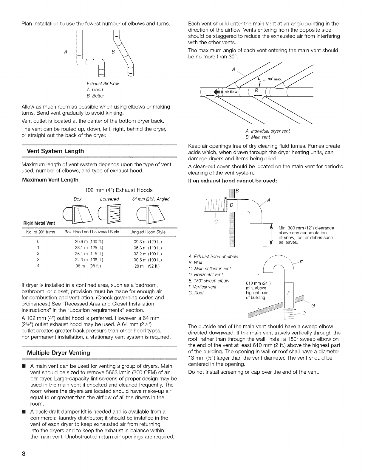
Venting
REQuirementS
.........ccscccccssccccossecccoscssecccessececessesecsessersens
INSTALLATION
INSTRUCTIONS
-
GAS
DRYER
...........:0000
9
Install
Leveling
LOGS........:.:ccccsccccsssscccssssecsssesececssesecsestecsenstersens
9
Make
Gas
Connection
.......ccccsscccosssseccssssecsenssecessaesecceesecsessersens
9
COnnect
VEN
......cccscssssccccssscecsssssecsosacecsosscecceseatecsestecsestecsoateess
9
Complete
Installation
........c.ccssceccssscecsonscecsoteceesesesaturessarursssantess
9
MAINTENANCE
INSTRUCTIONS.
..........:0ccseseeeeeeeeesseeeeerrenene
10
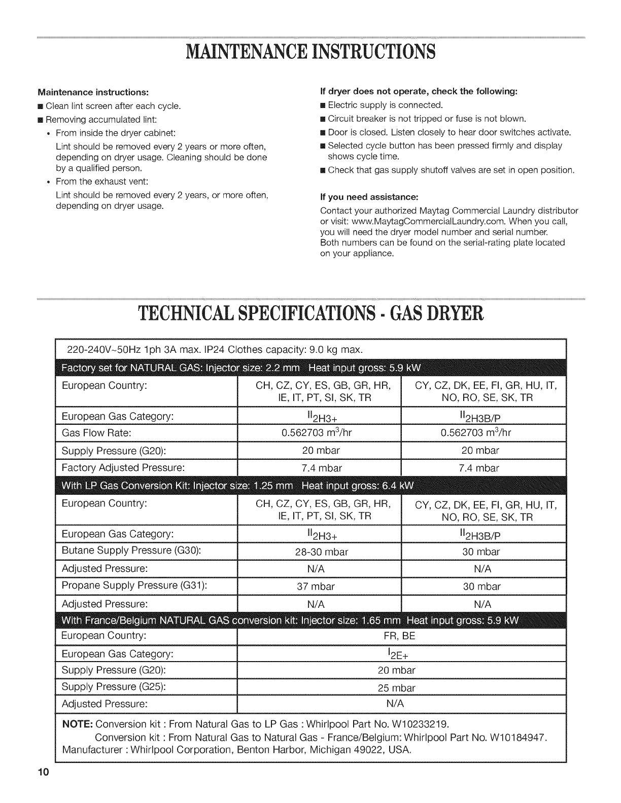
TECHNICAL
SPECIFICATIONS
~
GAS
DRYER............::0:0
10
REVERSING
THE
DOOR
SWING
(OPTIONAL).............00:00+
1
ELECTRONIC
CONTROL
SETUP?
............ss:ccessersseessresnenseeeees
13
WARRANTY
.....0::0:eccccenercesenneensensesenansesenneensneseseennsnnnnnesesnnenenanss
17
TABLE
DES
MATIERES
SECURITE
DU
SECHE-LINGE
...........22222..:::ce::eceeeeeeeeeereeeeeee
18
ELIMINATION
DU
SECHE-LINGE.
..........::cc:cecccerceeesseeenereeeecee
19
EXIGENCES
D’INSTALLATION...........2222:2:::0:ceceeeeeeeeeeeeeeseteeeees
19
Outillage
et
PISCES
.........esecccessscccessececsenscecsesscecsesscecsestecsessecsens
19
EXIQENCeS
C’EMPIlACEIMeENt
........:ccccessccecessececsssececessscecseeseceeness
20
Spécifications
électriques
-
séche-linge
&
GaZ
......cscccssseceens 21
Spécifications
de
lalimentation
EN
Gaz
.......cccssccessssecestreeeens
22
Exigences
concernant
l@VACUATION
........ccsccccesscccossscesesseecenees
23
INSTRUCTIONS
D’INSTALLATION
-
SECHE-LINGE
A
GAZ
|...
21.
.cessecccceeeececcn
eee
eneeen
ee
eeeeeeneeeneeeeeees
24
installation
des
pieds
de
nivellerMent...........cccscccccsssccessseseenees
24
Raccordement
a
la
canalisation
de
Gaz
.......ccscccsssccesstseseenees
25
Raccordement
du
conduit
c’Evacuation
.......:cccscccesseseceenees
25
Achever
Pinstallation
........cccsccccosscsccossecccossesecerseeeseseuursssesecsenses
25
INSTRUCTIONS
D’ENTRETIEN.........:c2::cccseecceeceneeeeseeeneenseeenes
25
FICHE
TECHNIQUE
-
SECHE-LINGE
A
GAZ
...............00+
26
INVERSION
DU
SENS
D’OUVERTURE
DE
LA
PORTE
.........
27
REGLAGE
DE
LA
CARTE
DE
CIRCUITS
ELECTRONIQUES.
...........22::::ccceseeeeeeeeeeeeeereeees
29
GARANTIE
..........-2ccccceceneececeeneennneceneeneenenenesesenanansensennaaeseneenennaee
33
INDICE
SEGURIDAD
DE
LA
SECADORA..
...........22.2::::::cceeeeecreeeeeeeeeeee
34
ELIMINACION
DE
LA
SECADORA.
...........sceeceeeeeeeneseens
35
REQUISITOS
DE
INSTALAGION
........:cccccesseeceeereeeneenes
35
PieZas
Y
NEPPAMENtAas
..........ccccccecececececesescensnsnsncacacecececsesesess
35
Requisitos
de
UDICACION
..........ccececccccececesescensnsnsncacacacececsesesess
35
Requisitos
eléctricos
-
S@Cadora
4
GAS
......ccsesescscscscececeesesess
37
Requisitos
del
SUMINISTO
CO
GAS......cccccsscecestssecsstssecsstssersens
37
Requisitos
de
VENtHACION
........ccccecccececesescensnsnsncacacacececsesecess
38
INSTRUCCIONES
DE
INSTALACION
-
SECADORA
A
GAS.
0...
.cessseececsneesenseetsecceseaaeeeesnaeeusenceensanenessaeas
40
Instalaci6n
de
las
patas
nivelacoras
.........c:csesescscscscececeesesess
40
Conexion
Gel
SUMINISTIO
GO
GaS............ccecececececssesessensnenenaees
40
Conexion
del
ducto
dé
ESCADE
..........ccececececececssseeesensnenenaeas
40
Complete
la
inStalacion
.....ccccccccccccccsesecusecccccecerstesesesesseeenaees
40
INSTRUCCIONES
DE
MANTENIMIENTO
............2:::cceceeeeeeee
41
ESPECIFICACIONES
TECNICAS
-
SECADORA
A
GAS
......
41
COMO
INVERTIR
EL
SENTIDO
DE
APERTURA
DE
LA
PUERTA,
.........ccecccceseseeceerseeenenennenneeeeneneeeneennnnnnesnnenneneney
42
PROGRAMAGION
DEL
CONTROL
ELECTRONIC
.............
44
GARANTIA.......cccsecesnecesnescenssessesesesecsesessesesesacsecaenessenecseneenenecess
48
INDICE
SICUREZZA
DELL’ASCIUGATRICE.
.........22....:::::::ececceeeeeeeeeeees
49
VELIMINAZIONE
DELL’ASCIUGATRICE
............:.::cs1:eereeeeesees
50
REQUISITI
D'INSTALLAZIONE.
.........22.:.-:::::::ececceseereeeeeeeeeeteeees
50
AttreZZi
©
COMPONENEL........csccccessccccessssccessececesscsecosssseceestseseeness
Requisiti
di
ubicazione
Requisiti
elettrici
-
asciugatrice
@
GAS
ee
eceeeeeeteeeteeteees
52
Requisiti
di
alimentazione
Gel
QaS..........ccssscccstssecessssecsstssecsens
52
REQUISIEL
Ci
SCALICO
oo.
ccccecccececccccecececeseeceensnsncacacscececsesesess
53
ISTRUZIONI
DI
INSTALLAZIONE
-
ASCIUGATRICE
DB
GAS.
0c
ceceecescn
eevee
ee
encaneenenne
ee
suanenenanennenaesecaaeesesaaeeseeasensaaaenseaaass
55
installazione
dei
piedini
di
regolaZione’
..........ccsscccesssecsetsseceens
55
Eseguire
il
Colleganento
QaS
........:cccssssccsssssecsstssecsenssecsetssersens
55
Gonnessione
dello
SCAriCO
oo.
cecccetceeeeeceeeceteeseeeeeneeeteeesteeteaes
55
Completamento
dell’installaZione
.........::ccccssersctssecsessecsotareess
56
ISTRUZIONI
DI
MANUTENZIONE.
............:::cseeeensseeeseeenereeeenee
57
DATI
TECNICI
-
ASCIUGATRICE
A
GAS.
..........2::::eeeeeeee
57
INVERSIONE
DELLA
ROTAZIONE
DI
APERTURA
...............
58
CONFIGURAZIONE
DEI
CONTROLLI
ELETTRONIC!
..........
60
GARANZIA
.....ccesccsccssccssceecesneessenaeesneneesaeesnenaeeeaeeaneneteaetasenaeersase
64