10
Your dryer can be installed in a basement, laundry room, or
recessed area.
Companion appliance locaon requirements should also be
considered.
Do not install or store the dryer where it
will be exposed to the weather. Proper installaon is your
responsibility.
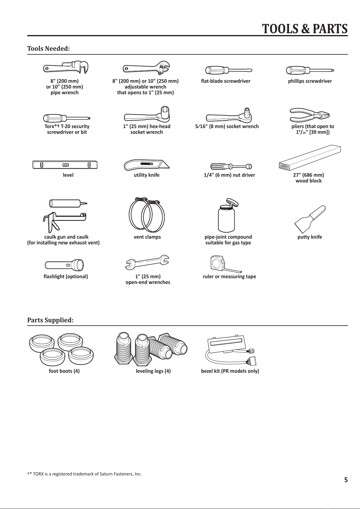
You will need:
■A grounded electrical outlet located within 6 . (1.8 m) of
where the power cord is aached to the back of the dryer.
See “Electrical Requirements.”
■A level oor with a maximum slope of 1" (25 mm) under
enre dryer. Installing the dryer on so oor surfaces,
such as carpets or surfaces with foam backing, is not
recommended.
Electric dryer installation clearances
■The locaon must be large enough to allow the dryer door
to be fully opened.
■Addional spacing should be considered for ease of
installaon and servicing. The door opens more than 180°.
■Addional clearances might be required for wall, door, and
oor moldings.
■Addional spacing of 1" (25 mm) on all sides of the dryer is
recommended to reduce noise transfer.
This dryer may be installed in a recessed area or closet. For
recessed area and closet installaons, minimum clearances
can be found on the warning label on the rear of the dryer
or in “Dimensions/Clearances.”
The installaon spacing is in inches and is the minimum
allowable. Addional spacing should be considered for ease
of installaon, servicing, and compliance with local codes and
ordinances.
If closet door is installed, the minimum unobstructed air
opening in the top and boom is required. Louvered doors
with equivalent air openings are acceptable.
The dryer must be exhausted outdoors.
24 in.2
(155 cm2)
48 in.2
(310 cm2)3"
(76 mm)
3"
(76 mm)
Closet
door
Front
View
ELECTRIC DRYER INSTALLATION REQUIREMENTS
closet
door
front
view
■To contact a qualied electrical installer.
■ To be sure that the electrical connecon is adequate and in
conformance with the Naonal Electrical Code, ANSI/NFPA
70-latest edion and all local codes and ordinances.
■ The Naonal Electrical Code requires a 4-wire power
supply connecon for homes built aer 1996, dryer circuits
involved in remodeling aer 1996, and all mobile home
installaons.
■ A copy of the above code standards can be obtained from:
Naonal Fire Protecon Associaon, One Baerymarch
Park, Quincy, MA 02269.
■ To supply the required 3 or 4 wire, single phase, 120/240
volt, 60 Hz., AC only electrical supply (or 3 or 4 wire,
120/208 volt electrical supply, if specied on the serial/
rang plate) on a separate 30-amp circuit, fused on both
sides of the line. A me delay fuse or circuit breaker is
recommended. Connect to an individual branch circuit.
Do not have a fuse in the neutral or grounding circuit.
■Do not use an extension cord.
■ If codes permit and a separate ground wire is used, it is
recommended that a qualied electrician determine that
the ground path is adequate.