Tyco Fire Product Gem DUOMATIC User manual

DUOMATICTM DRY SYSTEMS
4 and 6 INCH
TABLE OF CONTENTS
SECTIONS
General Description . . . . . . 2
Approvals and Standards . . . 2
Technical Data . . . . . . . . . 3
System Design
Considerations . . . . . . 3
System Air Pressure
Requirements . . . . . . 4
Friction Loss . . . . . . . 4
Vatve Trim . . . . . . . . . 4
Principles of Operation . . . 5
installation . . . . . . . . . 6
In Case of Alarm . . . . 8
Resetting Procedure . . . . 8
Care and Maintenance . . . . 10
Warranty . . . . . . . . . . . 11
Ordering Procedure . . . . . . 11
Conversion Factors . . . . . . 12
Weights . . . . . . . . . . . . 12
FIGURES
A - Duomatic Dry System . . . 1
B - InstaHation Configuration and
Clearance Dimensions . . 2
C - Duomatic Basic Trim . . 7
D - Duomatic Accelerator Trim 8
GRAPHS
.OPTlONAL \
v AUTOMATIC
DRAIN VALVE.
A - System Air Pressure
Requirements . . . . 5
TRIM. REFER TO FIGURES
B, C, AND D FOR DETAILS
OF TRIM ARRANGMENTS. WATER
SUPPLY
FIRE DEPT.
CONNECTION)
FIGURE A
B - Pressure Loss Versus Flow 5 SCHEMATIC OF TYPICAL DUOMATIC DRY SYSTEM
AUTOMATIC SPRINKLERS
P I I
HEAT DETECTORS
- -------- MONITOR SWITCH’ w
l- -----------
I
I SYSTEM
I SHUT-OFF
I VALVE.
I
PRESSURE
ALARM
BELL
A- 4 MULTIMATIC
DELUGE VALVE
AUTOMATIC
CONTROL UNIT
WITH BATTERIES
* INCLUDED WITH DUOMATIC BASIC CHECK VALVES
(REQ’D WITH
Printed in U.S.A. 12-89 TDll50
OBSOLETE

4 INCH SYSTEM
Dim Inches
A’ 26 (MM)
(6601
6 INCH SYSTEM
Dim Inches
A* 30
: 1215 [;A:{
ED 2215 g8”:;
F a (200)
* F520 81F5201
FIGURE B
INSTALLATION CONFIGURATION
AND CLEARANCE DIMENSIONS
SYSTEM AIR
PRESSURE GAUGE
SYSTEM
A-4 MULTIMATIC
DELUGE VALVE
FRONT VIEW
GENERAL DESCRIPTION
The 4 and 6 inch Duomatic Dry Sys-
tems (Ref. Figure A) are double inter-
locked dry sprinkler systems designed
for use in applications, such as
refrigerated areas, requiring the maxi-
mum degree of protection against in-
advertent flooding of the sprinkler sys-
tem piping.
The Duomatic Dry System utilizes a
Model A-4 MultimatH Deluge Valve
and a Model F520 or F5201 Swing
Check Valve, with releasing trim con-
sisting of both a Solenoid Valve and a
Dry Pilot Actuator in a series con-
figuration. The Swing CheckValve iso-
lates the Deluge Valve from the sys-
tem air pressure, which holds the Dry
Pilot Actuator closed. The Solenoid
Valve remains closed until it is electri-
cally energized by an automatic con-
trol unit (deluge releasing panel) that
is operated by either a fire detection
device or manual pull station.
In order for the Duomatic Dry System
to actuate, two independent events
must occur. The automatic control unit
must operate and open the Solenoid
Valve upon automatic or manual
operation of the electric fire detection
circuit and, the sprinkler system piping
must lose air pressure due to operation
of one or more sprinklers.
The Duomatic Dry System will
automatically actuate only when both
the Dry Pilot Actuator and the Solenoid
Valve are open at the same time. Ac-
cidental opening of just the Dry Pilot
Actuator (for example: a lift truck ac-
cidentally dislodges a sprinkler) or,
just energizing the Solenoid Valve (for
example: an electrical storm operates
the automatic control unit) will only
cause an alarm, and will not actuate
the system or flood the sprinkler sys-
tem piping.
Both the 4 and 6 inch Duomatic Dry
Systems may be equipped, as an op-
tion, with the Model F311 Accelerator.
In the case of the Duomatic Dry Sys-
tem, the F311 operates as a quick
opening device for the Dry Pilot Ac-
tuator and provides a reduction in the
time to open it following the operation
of one or more automatic sprinklers.
APPROVALS AND STANDARDS
The 4 and 6 inch Duomatic Dry Sys-
tems are Factory Mutual Approved
Refrigerated Area Systems for use in
refrigerated rooms or buildings.
The 4 and 6 inch Duomatic Dry Sys-
tems are Underwriters Laboratories
Inc. Listed Double Interlock Type
Water Control Valves.
The principle components of the
Duomatic Dry System are individually
listed and approved as follows: the
Model A-4 Multimatic Valves, Model
F52O/F5201 Swing Check Valves,
Model B-l Dry Pilot Actuator, and
Model F180 Manual Control Station
are listed by Underwriters
Laboratories Inc. (UL) and
Underwriters’ Laboratories of Canada
(ULC), and approved by Factory
Mutual Research Corporation (FM).
The 24VDC, R821 OAI 07 Solenoid
Valve is UL Listed and FM Approved
under the name of Automatic Switch
Company. The PSlO-2 Pressure
Alarm Switch and PS40-1 Low Pres-
sure Alarm Switch are UL Listed and
FM Approved under the name of Pot-
ter Electric Signal Company.
-2-
OBSOLETE

k----E ‘I , PRIMING CUP
LOW PRESSURE
ALARM SWITCH PRIMING VALVE
D-
REAR VIEW
DRY PILOT
ACTUATOR
SOLENOID
\,A, \,c
LEFT SIDE VIEW
WARNlNG
The 4 and 6 inch Duomatic Dry Sys-
tems with the associated trim
described herein must be installed
and maintained in compliance with
this document, as well as with the ap-
plicable standards of the National
Fire Protection Association, in addi-
tion to the standards of any other
authorities having jurisdiction.
Failure to do so may impair the in-
tegrity of these devices.
The owner is responsible for main-
taining their fire protection system
and devices in proper operating con-
dition. The installing contractor or
manufacturer should be contacted
relative to any questions.
TECHNICAL DATA
The 4 and 6 inch Duomatic Dry Sys-
tems, as well as their associated trim,
are rated for use at a minimum service
pressure of 20 psi and a maximum ser-
vice pressure of 175 psi
The following is a list of the Technical
Data Sheets for the valves and
devices which are required as part of
the Duomatic Dry System:
Deluge Valve . . . . . . . . TDI 17G
Swing Check Valve . . . . . TD320
Dry Pilot Actuator* . . . . . TD117W
Solenoid Valve* . . . . . . . TDI 19
Manual Control Station* . . TD121
Pressure Alarm Switch* . . TD213
Low Pressure Alarm Switch* TD232
*Included with Duomatic Basic Trim
The following is a list of the Technical
Data Sheets for optional items which
may be considered for use with the
Duomatic Dry System:
Accelerator* . . . . . . . TDI 09
System Pressure Maintenance
Devices (select one)
-Air Pressure Reducing Type
. . . . . . . . . . . . . . . . TD111
-3-
-Air Compressor Control Type
. . . . . . . . . . . . . . . .TD112
-Nitrogen Press. Reducing Type
. . . . . . . . . . . . . . . .TD113
Monitor Switch, OS.& Y. . .TD205
Water Motor Alarm . . . . .TD250
Main Control and System Shut-off
Valves, OS&Y. . . . . . . .TD302
Check Valve (for Fire Department
Conn.) . . . . . . . . . . .TD315
Fire Department Connection TD411
Automatic Drain Valve . . .TD425
*Included with Duomatic Accelerator
Trim
System Design Considerations
The automatic sprinklers, as well as
the electric automatic control unit, fire
detection devices, manual pull sta-
tions, and signaling devices, which are
utilized with the Duomatic Dry System
OBSOLETE

must be UL Listed, ULC Listed, or FM
Approved, as applicable.
Factory Mutual Research Corporation
does not recognize the use of cross-
zoned detection circuitry for use with
electrically actuated sprinkler sys-
tems.
Factory Mutual Research Corporation
requires that detection devices in
refrigerated areas be of the fixed
temperature type. In addition, they are
to have a temperature rating less than
that of the sprinklers and, preferably,
as low as possible for the given am-
bient conditions.
The deluge valve, swing check valve,
and all interconnecting piping must be
located in a readily visible and acces-
sible location and in an area which can
be maintained at a minimum tempera-
ture of 4O”F/4’C.
NOTE
Heat tracing is not permitted for the
deluge valve, swing check valve, or
any of the interconnecting piping.
Heat tracing can promote the forma-
tion of hardened mineral deposits
which can prevent system operation.
Heat tracing can also result in
damage to the Multimatic Valve
Diaphragm Assembly.
In planning the installation, considera-
tion must also be given to the disposal
of the large quantities of water which
may be associated with draining the
system or performing a flow test.
The flanged inlet and outlet connec-
tions are faced and drilled per ANSI
Standard 816.1. The grooved outlet
connection of the F5201 Swing Check
Valve is cut in accordance with the
specifications given in Table A. Instal-
lation configuration and clearance
dimensions are given in Figure B.
Refer to Figure A for recommenda-
tions concerning a fire department
connection for the Duomatic Dry Sys-
tem.
In order to be able to readily perform
the System Inspection Procedure
described in the Care and Main-
tenance section, it is recommended
that a System Shut-off Valve be in-
stalled at least two feet above the
Model F52O/F5201 Swing Check
Valve, as shown in Figure A. The Sys-
tem Shut-off Valve should be a listed
or approved (as appropriate) indicat-
ing valve with a supervisory switch to
monitor the normally open position.
System Air Pressure Requirements
Graph A shows the minimum
Duomatic Dry System air pressure re-
quirement as a function of the water
GASKET SEALING
SURFACE
I DIMENSIONS IN INCHES I
NOMINAL 0.0. C E
VALVE OUTSIDE GA&ET GROOVE
SIZE DIAMETER SEAT DIAMETER %Y “0°F”
WIDTH DEPTH SQUARE
4 4 500;:;:; .625 1 ::;I ,375: .;:I 4.334: :o”;,” ,050 ,030
6 6.6251 z:; .625; ‘:;I ,375: -,“tf 6.455; ‘,“;; ,050 ,030
TABLE A
DIMENSIONAL SPECIFICATIONS FOR CUT GROOVE OUTLET
CONNECTIONS ON MODEL F5201 CHECK VALVES
supply pressure. Use of an automatic and a 1000 GPM or greater flow rate
air or nitrogen maintenance device is for 6 inch systems. For 6 inch system
recommended and may be required by flow rates less than 1000 GPM refer to
the authority having jurisdiction. Graph B.
NOTES
The dew point of the air or nitrogen
must be maintained below the lowest
ambient temperature to which the
Duomatic Dry System piping will be
exposed. Accumulation of water in the
connection to the Dry Pilot Actuator
will lower the air pressure at which
the Dry Pilot Actuator will open and
possibly prevent proper operation.
Also, introduction of moisture into the
system piping that is exposed to freez-
ing temperatures can create ice build
up which could prevent proper opera-
tion of the system.
SIZE SCH. 40
OF C=lOO
VALVES FT. OF PIPE
4” 20
6” 26
Valve Trim
Figure C illustrates the Duomatic
Basic Trim and Figure D illustrates the
Duomatic Accelerator Trim. Both trim
arrangements are designed for use
with eitherthe 4 or 6 inch Duomatic Dry
Systems.
When small non-tank mounted com-
pressors are used, the supply of air
can be taken from the protected area
of lowest temperature, to avoid the use
of a desiccant air dryer.
Friction Loss
The nominal pressure losses in
pounds per square inch (psi) versus
flow rate in U.S. gallons per minute
(GPM) for the 4 and 6 inch combina-
tions of the Model A-4 Multimatic Valve
with either the Model F520 or F5201
Swing Check Valve are shown in
Graph B.
The nipples utilized in the trim arrange-
ments are Schedule 40 black steel per
ASTM A53 and they are threaded per
ANSI Standard B1.20.1. Fittings are
either malleable iron per ANSI B16.3
or cast iron per ANSI B16.4. The globe
and angle valves are nitrile rubber disc
sealed, bronze bodied, rising stem
valves with fluoroplastic impregnated
packing. The ball valves are one-
quarter turn type constructed of cor-
rosion resistant copper alloys with
glass filled PTFE seals. The strainers
are bronze bodied with a 50 mesh
S30400 stainless steel screen which
can be removed for cleaning.
The approximate friction losses, based The swing type check valve located in
on the Hazen and Williams formula the air supply connection is bronze
and expressed in equivalent length of bodied nitrile rubber disc sealed, the
Schedule 40 pipe with C = 100, are swing type check valve with 3132 inch
given below for each size deluge and orifice which is located in the ac-
swing check valve combination. The celerator connection is bronze bodied,
approximate friction losses have been and the spring loaded check valve is
calculated on the basis of a 300 GPM brass bodied Buna-N O-ring sealed.
or greater flow rate for 4 inch systems The pressure relief valve is br+--
-4-
OBSOLETE

50 75 100 125 150 175
WATER SUPPLY PRESSURE IN PSI
GRAPH A
DUOMATIC DRY SYSTEM AIR PRESSURE REQUIREMENTS
10.0
9.0
8.0
7.0
6.0
3.0
300 500 1000 2000 3000
FLOW RATE IN U.S. GALLONS PER MINUTE (GPM)
GRAPH B
NOMINAL PRESSURE LOSS VERSUS FLOW
FOR THE DUOMATIC DRY SYSTEM
DELUGE VALVE AND CHECK VALVE COMBINATION
bodied with stainless steel springs and
a Buna-N seal, and the F793
Automatic Drain Valve is bronze
bodied with a beryllium copper spring
and stainless steel or brass ball.
The water supply and system air pres-
sure gauges are constructed of cor-
rosion resistant materials. The system
air pressure gauge has markings of O-
250 psi and O-l 7 kg/cma; and the water
supply pressure gauge is marked O-
300 psi and O-25 kg/cm% The gauges
are individually listed and approved for
fire protection system service. The
three port gauge test valves are
bronze bodied, rising stem units with
fluoro-plastic impregnated asbestos
packing and a metal-to-metal seat. All
trim components form a part of the FM
Approval for the Duomatic Dry Sys-
tem.
PRINCIPLES OF OPERATION
The 4 and 6 inch Duomatic Dry Sys-
tems are double interlocked dry
sprinkler systems. As indicated in the
General Description section, two inde-
pendent events resulting in opening of
both the Dry Pilot Actuator and the
Solenoid Valve must occur to actuate
the Duomatic Dry System.
When the Duomatic Dry System is set
for service, the diaphragm chamber of
the Model A-4 Multimatic Valve is pres-
surized through the diaphragm cham-
ber supply connection (Ref. Figure C).
The Multimatic Valve is a differential
type valve which depends upon the
water pressure in the diaphragm
chamber to hold the clapper closed
against the water supply pressure.
The Multimatic Valve has a nominal
trip ratio of 2.5 to 1, i.e., the valve
operates when pressure in the
diaphragm chamber is reduced to ap-
proximately two-fifths of the water sup-
ply pressure.
Opening of both the Dry Pilot Actuator
and the Solenoid Valve or, operating
the Manual Control Station (Ref.
Figure C) will release water from the
Muttimatic Valve diaphragm chamber
faster than it can be replenished
through the l/8 inch diameter restric-
tion in the inlet connection to the Mul-
timatic Valve diaphragm cover. A rapid
pressure drop then results in the
diaphragm chamber and the differen-
tial between the diaphragm chamber
and waterway is eliminated. The water
supply pressure then forces the water-
way clapper open, permitting a flow of
water to the Duomatic Dry System
piping. Water flowing into the system
also flows through the normally open
Alarm Control Valve (Ref. Figure C) to
the Pressure Alarm Switch, which ac-
tuates the system alarm signal.
The Duomatic Dry System will
automatically operate only when both
the Solenoid Valve and the Dry Pilot
Actuator are open at the same time.
Opening of just the Dry Pilot Actuator
(e.g., a lift truck accidentally dislodges
a sprinkler) or just energizing the
Solenoid Valve (e.g., an electrical
storm operates the automatic control
unit) will only cause an alarm, via the
low pressure alarm switch or the
automatic control unit, as applicable,
to indicate that the system requires at-
tention. The system will not actuate or
flood the sprinkler system piping.
As an option, the 4 and 6 inch
Duomatic Dry Systems may be
equipped with a Model F311 Ac-
celerator for the purpose of obtaining
a reduction in the time for the Dry Pilot
Actuator to open following the opera-
tion of one or more automatic
sprinklers.
With the Duomatic Accelerator Trim
-5-
OBSOLETE

(Ref. Figure D), the communication be-
tween the system air pressure and the
Dry Pilot Actuator is made directly
through the Accelerator Trim. The
F311 Accelerator automatically ad-
justs to small as well as slow changes
in system pressure, but trips when
there is a rapid and steady drop in
pressure (such as will occur when a
sprinkler operates). Upon tripping, the
F311 Accelerator will relieve svstem
air pressure from the Dry Pilot Aciuator
faster than it can be replenished
through the 3132 inch diameter orifice
in the clapper of the l/2 inch Swing
Check Valve (Item 4, Figure D), result-
ing in quick opening of the Dry Pilot Ac-
tuator following a sprinkler operation.
The F311 Accelerator is described in
Technical Data Sheet TD109.
INSTALLATION
6. Connect the Air Supply Connec-
tion to an air or nitrogen supply.
Use of an automatic air or nitrogen
maintenance device is recom-
mended and may be required by
the authority having jurisdiction.
Refer to Graph A for Duomatic Dry
System air pressure requirements.
The deluge valve, swing check valve, 7. The Low Pressure Alarm Switch is
and all interconnecting piping must be to be adjusted to operate on falling
installed in a readily visible and acces- pressure at approximately 6 psi
sible location and in an area which can below the minimum Duomatic Dry
be maintained at a minimum tempera- System air pressure requirement
ture of 4O’F/4’C. shown on Graph A.
NOTE
Heat tracing is not permitted for the
deluge valve, swing check valve, or
any of the interconnecting piping.
Heat tracing will promote the forma-
tion of hardened mineral deposits
which can prevent valve operation.
Heat tracing can also result in
damage to the Multimatic Valve
Diaphragm Assembly.
8. A desiccant air dryer, when
specified, is to be installed be-
tween a drip leg and the system
pressure maintenance device.
9. Make suitable arrangements for
disposal of alarm line and system
drainage water. Drainage water
must be directed such that it will
not cause damage or result in
dangerous conditions.
The 4 and 6 inch Duomatic Dry Sys-
tems must be installed in accordance
with the following instructions. Proper
operation of the Duomatic Dry System
depends upon it being installed in ac-
cordance with the instructions given
below. Failure to follow these instruc-
tions may prevent the devices from
functioning properly as welLis void
listings, approvals, the
manufacturer’s warranties.
10. Install the Duomatic Accelerator
Trim as shown in Figure D, if ap-
plicable. In order to install the trim,
the Item 33 union, Item 46 nipple,
and Item 35 elbow at the inlet con-
nection to the Dry Pilot Actuator
must first be removed (Ref. Fig. C).
The drain tubing must be installed
with smooth bends that will not
restrict flow.
1. Tighten all flange mounting fas-
teners uniformly using a crossdraw
sequence. The required fasteners
are described in the Ordering
Procedure section. Tightening tor-
ques are as follows:
Valve Size
4"
6"
Torque
40 -50 ft.Ibs.
50 -60 ft. Ibs.
The connection to the system
piping must be located on the sup-
ply side of the System Shut-off
Valve (Fig. A) but at least two feet
above the level of the check valve
priming water, so that drain
back/condensate will not flow into
the Accelerator piping.
2. When assembling pipe thread con-
nections, apply pipe thread sealant
sparingly to the male pipe threads
only.
3. Install the Duomatic Basic Trim as
shown in Figure C. All drain tubing
must be installed with smooth
bends that will not restrict flow.
4. Attach the Duomatic Nameplate to
the 2 inch high x 4 inch wide
nameplate mounting pad on the
Handhole Cover of the deluge
valve (see item 65 of Figure C).
Place the Duomatic Nameplate
over the manufacturer’s logo
nameplate, if one is located on the
pad.
5. Connect the Diaphragm Chamber
Supply Control Valve to the inlet
side of the main control valve in
order to facilitate setting of the
deluge valve.
Connections to a feed or cross
main must be made either to the
side or top of the main.
NOTE
Failure to follow the above in-
structions can result in flooding of
the Accelerator and accidental
tripping due to clogging of its
restriction.
11. If an F311 Accelerator has been in-
stalled, close the Accelerator Con-
trol Valve.
NOTE
The Accelerator Control Valve
must be closed during hydrostatic
testing of the system, in order to
prevent flooding of the Accelerator
and clogging of the restriction.
Clogging of the Restriction can
result in accidental tripping of the
Accelerator.
12. Conduit and electrical connections
are to be made in accordance with
the requirements of the authority
having jurisdiction and/or the Na-
tional Electrical Code.
NOTE
The Solenoid Valve is only to be
used in conjunction with an
automatic control unit (deluge
releasing panel) that is listed or
approved (as appropriate) for fire
protection releasing service.
-6-
OBSOLETE

AIR SUPPLY CONTROL
VALVE (NORMALLY
s\ PRIMING VALVE
35 yylw)LY
CONNECTION
4% \
33
DRY PILOT
ACTUATOR
BLEED-OFF
65
53 \ / \
VALVE
\ u V _’ Iv’
PRIMING TEST VA
yv&,.LY
DRY PILOT
ACTUATOR
(NORMALLY CLOSED)
PRESSURE
:M WATER
Y PRESSURE
3/4” NPT CONNECTION
COMPRESSION NUT)
TO DRIP
FUNNEL
1-l/4” Gauge Test Valve
(2 req’d)
2-250 lb. Air Pressure
Gauge
3-300 lb. Water Pressure
Gauge (2 req’d)
4-l/4” Angle Valve
5-M” Globe Valve
6-l/2” Globe Valve
(3 req’d)
7-l/2” Ball Valve (2 req’d)
8-112” Spring Loaded
Check Valve
g-112” Swing Type Check
Valve
1O-l /4” Pressure Relief
Valve
1l-1 /2” Y-Strainer
12-l /2” F793 Automatic
Drain Valve
DIAPHRAGM
CHAMBER SUPPLY
CONTROL VALVE
(NORMALLY OPEN) DIAPHRAGM
%EER
CONNECTION
13-Manual Control Sta-
tion, F180
14-Drip Funnel
15-Drip Funnel Bracket
Is-Bracket Connector
17-Priming Cup
18.3/32” Vent Fitting
19-2” Angle Valve
(2 req’d)
PO-Dry Pilot Actuator,
B-l
21 -Solenoid Valve, 24
VDC
22-Pressure Alarm 29-i/2” Tubing Con-
Switch nector (2 req’d)
23-Low Pressure 30-l /4” Tube, 15”
Alarm Switch 31-l/4” Tube 24”
24-l/4” Plug (2 req’d) (2 req’d) ’
25-l/2” Plug 32-l/2” Tube 15”
26-3/4” Plug (2 req’d) ’
27-l/2” x l/4” Bush- 33-l/2” Union (4 req’d)
ing (2 req’d) 34-l/2” 45’ Elbow
28-l/4” Tubing Con- 35-112” 90’ Elbow
nector (2 req’d) (9 req’d)
TO DRIP
FUNNEL
36-l/2” Tee (3 req’d)
37-l/2” x l/2” x l/4” Tee
(2 req’d)
38-i/2” x l/4” x l/2” Tee
(2 req’d)
39-3/4” x l/2” x l/2” Tee
40-l/2” Cross (2 req’d)
41-2” x l/2” x 2” Tee
42-l/4” x 1” Nipple
(2req’d)
43-l/4” x 2” Nipple
44-M” x 4” Nipple
45-l/2” x close Nipple
(3 req’d)
46-l/2” x i-1/2” Nipple
(13 req’d)
47-112” x 2” Nipple
(2 req’d)
48-i/2” x 2-l/2” Nipple
(2 req’d)
49-i/2” x 3” Nipple
50-i/2” x 3-l/2” Nipple
51-l/2” x 4” Nipple
52-l/2” x 4-l/2” Nipple
(2 req’d)
53-112” x 5” Nipple
54-112” x 5-l/2” Nipple
55-l/2” x 6-l/2” Nipple
(2 req’d)
56-l/2” x 7-l/2” Nipple
57-l/2” x close Nipple
for 4” valves,
l/2” x 2” Nipple
for 6” valves
58-l/2” x 2” Nipple for
4” valves,
i/2” x 3-i/2” Nipple
for 6” valves
59-l/2” x 2-l/2” Nipple
for 4” valves,
l/2” x 3-l/2” Nipple
for 6” valves
60-l/2” x 4-112” Nipple
for 4” valves
l/2” x 4” Nipple
for 6 ” valves
61-l/2” x close Nipple
for 4” valves
l/2” x 2” Nipple
for 6” valves
62-2” x 3” Nipple
63-2” x 4” Nipple
64-2” x 8” Nipple
65-Duomatic
Nameplate
FIGURE C
DUOMATIC BASIC TRIM
-7-
OBSOLETE

/ l/Z” CONNECTION TO
SYSTEM PIPING
FRONT VIEW
DRY PILOT ,
ACTUATOR 7,“‘4;
REAR VIEW
TO DRIP FUNNEL
DRY PILOT ACTUATOR
LEFT SIDE VIEW
FIGURE D
DUOMATIC ACCELERATOR TRIM
1-Accelerator, F311
2-250 lb. Air Pressure
Gauge
3-112” Plug
4-l/2” Swing Check
Valve with 3/32”
Orifice
5-l/2” Y-Strainer
6-l/2” Globe Valve
7-l/2” Tube 36” 11-l/2” x 3” Nipple
8-i/2” Tubin’g Connector
9-l/2” Tee
1O-l 12” x 1-l/2” Nipple
(3 req’d)
IN CASE OF ALARM
A. Immediately verify whether or not
a fire situation is present. If a fire
condition does exist, immediately
notify the local fire service and fol-
low the plan prescribed by the
authority having jurisdiction.
B. If a fire condition does not exist:
1. Close the Diaphragm Chamber
Supply Control Valve (Fig. C).
2. Close the system’s Main Control
Valve (Fig. A).
3. Open the Multimatic Drain Valve
(Fig. C).
4. Notify the alarm monitoring sta-
tions (if applicable) as well as the
authority having jurisdiction that
there is an impairment to the fire
protection system.
5. Determine if the false alarm was
caused by the electric fire detec-
tion system or a low pressure con-
dition.
Promptly correct the impairment
and return the fire protection sys-
tem to service, as soon as pos-
sible.
RESETTING PROCEDURE
The Duomatic Dry System will not
automatically reset after an operation.
It must be manually reset and it should
be restored to service as soon as pos-
sible.
NOTES
It is recommended that the individual
responsible for placing the Duomatic
Dry System in service develop a work-
ing understanding of the system in
general, prior to placing it in opera-
tion. These instructions, as well as in-
dividual instructions for the deluge
valve, swing check valve, dry pilot ac-
tuator, solenoid valve, manual con-
trol station, switches, accelerator (if
applicable), and pressure main-
tenance device should be reviewed.
After placing a fire protection system
in service, notify the proper
authorities and advise those respon-
sible for monitoring proprietary
and /or central station alarms,
The procedure is as follows:
1. Close the Diaphragm Chamber
Supply Control Valve (Fig. C).
2. Close the Duomatic System Main
Control Valve (Fig. A), Air Supply
Control Valve (Fig. C), and, if ap-
plicable, the Accelerator Control
Valve (Fig. D).
3. Open the System Main Drain Valve
(Fig. C), Multimatic Drain Valve
(Fig. C), Inspector’s Test Connec-
-8-
tion, and all auxiliary drains in the
system piping. Check to see that
the drainage water will not cause
damage or result in dangerous
conditions.
NOTE
Do not open the Inspector’s Test
Connection and auxiliary drains
if resetting after a system test;
otherwise, system air pressure
will be relieved unnecessarily.
4. Inspect for and clear all ice plugs,
where system piping is exposed to
freezing conditions and when there
has been a flow of water into the
system.
5. Close the System Main Drain
Valve, Inspector’s Test Connec-
tion, and all auxiliary drains in the
system piping. Leave the Multi-
matic Drain Valve open.
6. Depress the plunger of the
Automatic Drain Valve (Fig. C), to
verify that it is open and that the
Multimatic Valve has been com-
pletely drained.
7. Clean out the Strainer (Fig. C) in
the connection to the Multimatic
Valve Diaphragm Chamber.
8. Remove the Multimatic Valve
Handhole Cover and thoroughly
clean all interior parts of the Multi-
matic Valve. Make certain that the
two pressure equalizing vents in
the top of the waterway Clapper
are open and that all parts are free
of rust and scale.
OBSOLETE

Test the Clapper, Clapper Latch,
Diaphragm, and Flange & Push
Rod Assembly for freedom of
movement.
Inspect the Clapper Facing for any
sign of deterioration due ta chemi-
cals in the water or age.
Worn or damaged parts must be
replaced (see TDll7G).
9. Raise the Clapper and pivot the
Clapper Latch to allow the Clapper
to be reseated. After reseating the
Clapper, release the Latch so that
it resets on the boss at the edge of
the Clapper.
10. If the Duomatic Dry System was
actuated by operation of the
Manual Control Station (Fig. C),
push the operating lever up. Do not
close the hinged cover at this time.
Il. Open the Alarm Control Valve (Fig.
C), if it was closed to silence local
alarms.
It is recommended that the Alarm
Control Valve be wire sealed in the
open position with a No. 16 twisted
wire, the ends of which are
secured by a lead seal. The wire
seal should be tightly twisted
around the pipe nipple at the outlet
of the Alarm Control Valve and the
base of the sloped portion of the
Alarm Control Valve handle.
12. Replace all damaged or operated
sprinklers. Replacement sprinklers
must be of the same type and
temperature rating as those which
operated.
NOTE
In order to prevent the possibility
of a subsequent operation of an
overheated solder type sprinkler,
any solder type sprinklers which
were possibly exposed to a
temperature greater than their
maximum rated ambient must
also be replaced.
13. Service the air dryer, if applicable,
in accordance with the
manufacturer’s instructions.
14. Open the Priming Valve, close the
Priming Test Valve, and close the
Dry Pilot Actuator Bleed-off Valve
(Fig. C).
Pour water into the Priming Cup
until it remains full. Open the Prim-
ing Test Valve, and then close the
Priming and Priming Test Valves
after water stops discharging from
the Priming Test Valve.
15. Verify that priming water is not
leaking down into the Multimatic
Valve from the Check Valve. If
there is leakage, determine/correct
the cause of the leakage problem
(see TD320).
16. Open (energize) the Solenoid
Valve by manually operating the
automatic control unit.
17. Open the Diaphragm Chamber
Supply Control Valve (Fig. C) and
allow water to discharge from the
Dry Pilot Actuator. Close the
Diaphragm Chamber Supply Con-
trol Valve when air is no longer
present in the discharge from the
Dry Pilot Actuator.
18. If resetting after a test, open the
Duomatic System Shut-off Valve, if
applicable.
19. Open the Air Supply Controi Valve
(Fig. C) and pressurize the
sprinkler system in accordance
with Graph A.
20. Return the Solenoid Valve to its
normally closed position by reset-
ting the automatic control unit.
21. Fully open the Diaphragm Cham-
ber Supply Valve (Fig. C) and allow
time for full pressure to build up in
the Diaphragm Chamber of the
Multimatic Valve.
22. Operate (open) the Manual Control
Station (Fig. C). If necessary, first
open the hinged cover, and then
pull down on the operating lever.
SLOWLY close the operating
lever, by pushing it up, after air is
no longer present in the discharge
from the drain tubing. Close the
hinged cover and insert a new
break rod (PSN 92-289-I-008) in
the small hole through the top of
the enclosing box.
23. Verifv that orimina water is not
leak&g dowi into”the Multimatic
Valve from the Check Valve. If
there is leakage, determine/correct
the cause of the leakage problem
(see TD320).
24
25.
Inspect the drain connections from
the Dry Pilot Actuator and Manual
Control Station for leaks. Leaks, if
any, must be corrected before the
system is restored to service.
Replace the Multimatic Valve
Handhole Cover and Gasket. Be
sure that the pin in the back of the
Cover and the small hole in the
Handhole Cover Gasket are
properly oriented with the small
orifice near the lower front edge of
the handhole. Water will discharge
through this orifice if the Handhole
Cover is not properly secured in
place when the Main Control Valve
(Fig. A) is opened.Tighten all Cap
-9-
Screws uniformly using a cross-
draw sequence.
26. Partially open the Dry Pilot Ac-
tuator Bleed-off Valve (Fig. C).
Close the Dry Pilot Actuator Bleed-
off Valve after water ceases to dis-
charge.
27. Reset the F311 Accelerator (Fig.
D) as follows, if the system is so
equipped; otherwise, proceed to
Step 28.
a. Close the Accelerator Control
Valve.
b. Slowly remove the plug from the
Strainer at the Accelerator inlet to
relieve any inlet pressure. This
procedure will trip the Accelerator
if it is not already tripped.
c. Clean out the Strainer at the Ac-
celerator inlet.
NOTE
A clogged strainer can prevent
the Accelerator from properly
tripping the system.
d. Open the Accelerator Control
Valve one-quarter turn and blow
any residual water in the connec-
tion to the system piping out
through the Strainer.
e. Close the Accelerator Control
Valve and replace the Strainer
Plug.
f. Slowly remove the Vent Plug lo-
cated in the front of the Ac-
celerator Cover and bleed off any
residual pressure in the Ac-
celerator Differential Chamber.
g. Unscrew (counter-clockwise rota-
tion) the knurled Reset Knob at
the front of the Accelerator until it
resists further turning. A click,
which is the sound of the Lever
snapping back into the set posi-
tion, should be heard. Screw the
Reset Knob back in until it is finger
tight.
Replace the Vent Plug after ap-
plying a non-hardening type of
pipe sealant sparingly to the male
pipe threads only. Use of a
Teflon? based pipe joint com-
pound or Teflonf tape is recom-
mended.
Verify that the system pressure
has returned to normal.
Using a watch, note the time for
the pressure in the Differential
Chamber of the Accelerator to in-
crease to 10 psi, after the Ac-
celerator Control Valve is opened.
The time should be within the
range of values indicated below,
f DuPont Registered Trademark
OBSOLETE

for optimum performance of the
Accelerator.
System Air
Pressure,
PSI
20
25
30
40
50
60
Time to 10 psi, sec.
Min. Max.
40 160
29 116
23 92
15 60
12 48
9 36
NOTE
If the time to pressurize the Dif-
ferential Chamber of the F311
Accelerator is not within the
range of values given in the
above table or any otherresetting
problem is encountered, the Ac-
celerator Control Valve should
be closed and corrective action
taken (see TD109).
k. When the air pressure in the Dif-
ferential Chamber of the Ac-
celerator is equal to that in the
system, the Accelerator is set and
ready for service.
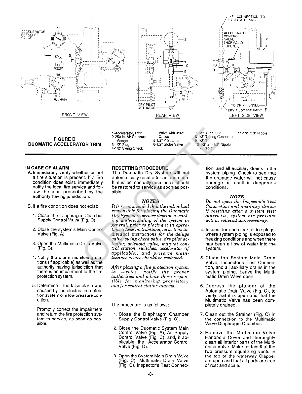
28. Slowly open the Main Control
Valve. Close the Multimatic Drain
Valve as soon as water discharges
from the drain connection. Ob-
serve the Automatic Drain Valve
for leaks. If there are leaks, either
the Clapper is not properly seated
and the Duomatic System must be
reset, or there is internal leakage
past the Clapper Facing or
Diaphragm. Determine/correct the
cause of the leakage problem. If
there are no leaks, fully open the
Main Control Valve (Fig. A).
29. Verify that the automatic control
unit is returned to a normal standby
condition.
30. It is recommended that the Main
Control Valve and the System
Shut-off Valve (if applicable) be
locked in the open position if they
are not monitored by supervisory
switches.
NOTE
After placing a fire protection sys-
tem in service, notify the proper
authorities and advise those
responsible for monitoring
proprietary and/or central station
alarms.
The Duomatic Dry System is now set
for service.
CARE AND MAINTENANCE
The Duomatic Dry System requires
regularly scheduled care and main-
tenance of its principle components,
as described in their individual techni-
cal data sheets. In addition, it is recom-
mended that the proper operation and
condition of the system be periodically
verified in accordance with the follow-
ing described inspection procedure.
Any impairment to the system must be
promptly corrected in order to maintain
the integrity of the system.
It is recommended that the System In-
spection Procedure be performed at
least semi-annually by a qualified In-
spection Service. The Duomatic Dry
System Inspection Procedure may be
followed in lieu of performing any of the
operational tests recommended in the
Technical Data Sheets of the Model
A-4 Multimatic Valve, Model
F52O/F5201 Swing Check Valve,
Model B-l Dry Pilot Actuator, Catolog
Number R821 OA107 Solenoid Valve,
Models PSlO-2 and PS40-1 Pressure
Switches, and Model F180 Manual
Control Station.
NOTES
1. It is recommended that in-
dividuals responsible for care
and maintenance of the Duomatic
Dry System develop a working
understanding of the system in
general, prior to performing in-
soection and /or maintenance
pdrocedures. These instructions,
as well as individual instructions
for the deluge valve, swing check
valve, dry pilot actuator, solenoid
valve, manual control station,
switches, accelerator (if ap-
plicable), and pressure main-
tenance device should be
reviewed.
2. The following procedures pertain
to the automatic control valve
portion of the Duomatic Dry Sys-
tem. Refer to the manufacturer’s
instructions and NFPA 13A for
care and maintenance procedures
for all other devices (e.g., electric
detection, main control and sys-
tem shut-off valves, supervisory
devices, sprinklers, etc.).
3. Before performing the System In-
spection Procedure, which will
result in operation of alarms,
notify the proper authorities and
all personnel who may be af-
fected.
4. Before closing a fire protection
system main control valve for
maintenance work on the fire
protection system which it con-
trols, permission to shut down the
affected fire protection system
must be obtained from the proper
authorities and all personnel who
may be affected by this action
must be notified.
System Inspection Procedure
I. Close the Main Control Valve (Fig.
A) and then open the Multimatic
Drain Valve (Fig. C).
2. Open (energize) the Solenoid
Valve by manually operating the
automatic control unit. Verify that
there is no leakage out the Dry
Pilot Actuator drain. Also, verify full
operation of the automatic control
unit and its associated alarms.
NOTES
During this procedure, the
Solenoid Valve is opened;
however, the Dry Pilot Actuator
should remain closed and the
Multimatic Valve Diaphragm
Chamber should remain pres-
surized.
This procedure is used to verify
that the Multimatic Valve will
remain set if the electric detection
system operates but the sprinkler
system remains in its normally
pressurized condition.
3. Open the Inspector’s Test Connec-
tion but be prepared to close it, as
well as the Accelerator Control
Valve (Fig. D), if applicable, im-
mediately after verifying the follow-
ing:
a. If the system is equipped with an
Accelerator, verify that the time to
Accelerator trip is essentially the
same as in previous tests, and
verify that the Diaphragm Cham-
ber Pressure Gauge (Fig. C)
drops to a pressure equivalent to
the reading that was recorded for
the trip point of the Multimatic
Valve during its most recent Sys-
tem Inspection Procedure.
b. Verify that the Low Pressure
Alarm Switch (Fig. C) and its as-
sociated alarms operate properly.
The Low Pressure Alarm Switch
should operate at the previously
established pressure (refer to In-
stallation section, Step 7).
Close the Inspector’s Test Con-
nection, and, if applicable, close
the Accelerator Control Valve.
4. Close the Diaphragm Chamber
Supply Control Valve (Fig. C).
5. Close the System Shut-off Valve
(Fig. A) after the system air pres-
sure has been restored to normal.
6. Manually restore the electric fire
detection system to a normal con-
dition in accordance with the
-1o-
OBSOLETE

manufacturer’s instructions. The
Solenoid Valve will then be de-
energized and returned to its nor-
mally closed position.
automatic control unit) to verify
automatic system operation.
7. Open the Diaphragm Chamber
Supply Control Valve.
13. Reset the Duomatic Dry System in
accordance with the Resetting
Procedure section.
8. Open the Main Control Valve (Fig.
A) one turn beyond the position at
which water just begins to flow from
the Multimatic Drain Valve.
WARRANTY
9. Close the Multimatic Drain Valve
(Fig. C).
Seller warrants for a period of one year
from the date of shipment (warranty
period) that the products furnished
hereunder will be free from defects in
material and workmanship.
IO. Close the Air Supply Control Valve
(Fig. C). For further details on Warranty, see
Price List.
11. Open the Dry Pilot Actuator by par-
tially opening the System Main
Drain Valve (Fig. C) to relieve air
pressure at the inlet to the Actuator.
Verify that there is no leakage out
the Dry Pilot Actuator.
NOTES
ORDERING PROCEDURE
Orders for valves, trim, and replace-
ment trim parts must include the
description and Product Symbol Num-
ber (PSN).
During this procedure, the Dry
Pilot Actuator is opened; however,
the Solenoid Valve should remain
closed and the Multimatic Valve
Diaphragm Chamber should
remain pressurized.
This procedure is used to verify
that the Multimatic Valve will
remain set if the Dry Pilot Ac-
tuator operates due to loss of sys-
tem air pressure and the electric
detection system remains in a nor-
mal condition.
Special Instructions:
The steel bolts and nuts required for
the attachment of mating flanges are
not provided with the Valves and must
be obtained separately. The bolts must
meek the minimum strength require-
ments of ASTM A307 (Grade B) and
nuts must meet the minimum strength
requirements of ASTM A563 (Grade
A). A description of the required fas-
teners to attach the F52O/F5201 Swing
Check Valve to the A-4 Multimatic
Valve is as follows:
12. Open (energize) the Solenoid
Valve by operating the automatic
control unit, and verify the follow-
ing:
a. Verify that the Multimatic Valve
operates, as is indicated by a dis-
charge of water from the System
Main Drain Valve and the
Automatic Drain Valve. The
Automatic Drain Valve may or
may not close depending on the
flow past the partially open Main
Control Valve.
Size
Of
Valve
4”
6”
Description Quantity
of per
Fasteners Mating Flanges
5/8” x 3-l/4”
Stud Bolts 8
5/8” Heavy
Hex Nuts 16
3/4” x 3-3/4”
Stud Bolts 8
314” Heavy
Hex Nuts 16
Also, record the pressure reading
on the Diaphragm Chamber Pres-
sure Gauge. (Fig. C) at the trip
point of the Multimatic Valve.
A description of the required fasteners
to attach mating flanges at the inlet
and outlet is as follows:
b. Verify that the Pressure Alarm
Switch (Fig. C) and its associated
alarms properly operate.
c. Verify that the Water Motor Alarm,
if applicable, properly operates.
NOTE
This procedure simulates opening
of both the Dry Pilot Actuator (loss
of system air pressure) and
Solenoid Valve (operation of the
Size
of
Valve
4”
6”
Description Quantity
of per
Fasteners Mating Flanges
5/8” x 2-3/4”
Heavy Hex
Head Bolts 8
518” Heavy
Hex Nuts 8
3/4” x 3” Hex
Head Bolts 8
314” Heavy
Hex Nuts 8
-ll-
NOTE
Use of an automatic air (nitrogen)
maintenance device is recommended.
Refer to the following data sheets for
technical data and ordering informa-
tion.
TDlll fortheModelF324AirMain-
tenance Device (pressure reducing
twd
TD112 for the Model F326AirMain-
tenance Device (compressor control
twe)
TD113 for the Model F328 Nitrogen
Maintenance Device (high pressure
reducing type)
Deluge Valve Assemblies:
Specify: (size) inch Vertical Model A-4
Multimatic Valve, PSN (specify).
4” . . . . . . . . . . . . . . PSN 52-404-l -013
6” .:. . PSN 52-404-l-015
Swing Check Valve Assemblies:
Specify: (size) inch Model (specify
number) Swing Check Valve, PSN
(specify).
Model F520(Flange x Flange)
4” . . . . . . . PSN 52-520-i -013
6” . . PSN 52-520-I -015
Model F5201(Flangex Groove)
4” . , . . . PSN 52-520-i -413
6” . . . . . . PSN 52-520-l -615
Duomatic Basic Trim (Fig. C):
Specify: Duomatic Basic Trim, PSN
52-304-l-l 13.
Duomatic Accelerator Trim (Fig. D):
Specify: Duomatic Accelerator Trim,
PSN 52-311-1-113.
Replacement Trim Parts:
Specify: (description) for use with
Duomatic Dry System, PSN (specify).
Figure C
1-l/4” Gauge Test
Valve
2-250lb.Air Pres-
sureGauge . . . . .
3-300 lb.WaterPres-
sureGauge
4-M” Angle Valve
5-112” Globe Valve
6-i/2” Ball Valve .
7-l/2” Sorina
PSN 46-005-l -002
PSN 92-343-l -012
PSN 92-343-l -005
PSN 46-048-l -002
PSN 46-047-l -004
PSN 46-050-l -004
LoadedCheck
Valve . PSN92-322-l -002
8-112” Swing Type
Check Valve . PSN 46-049-l -004
9-l/4” Globe Valve PSN 46-047-I-002
1O-1/4” Pressure
ReliefValve PSN92-343-I-020
1l-112” Y-Strainer PSN52-353-l -005
12-l /2” F793
AutomaticDrain
Valve . . . PSN52-793-l-004
13-ManualControl
Station,F180 PSN52-289-l-001
14-Drip Funnel PSN 92-343-I-007
15-Drip Funnel
Bracket PSN 92-211-l-003
1B-Bracket Connec-
tor ................... PSN 92-211-I-005
17-Priming Cup ........... PSN 92-346-l -004
18-3/32” Vent Fitting ....... PSN 92-032-l -002
OBSOLETE

19-2” Angle Valve (2
req’d) PSN 46-048-l -009
20-Drv Pilot Ac-
t&or. B-1
21 -Solenoid Valve,
24 VDC
22-Pressure Alarm
Switch
23-Low Pressure
Alarm Switch
PSN 52-280-l-001 I
PSN 52-287-l -024
PSN 54-281-I -002
PSN 54-281-l-003
Figure D
1-Accelerator, Model
F311 . PSN 52-311-l-001
2-250 lb. Air Pres-
sure Gauge PSN 92-343-I-012
4-W” Swing Check
Valve with 3/32”
orifice PSN 52-403-l -004
5-l/2” Y-Strainer PSN 52-353-l-005
6-l/2” Globe Valve PSN 46-047-l -004
CONVERSION FACTORS
Parenthetical metric conversions cited herein are
approximate.
1 inch = 25.400mm
1 psi = 6.895kPa
= 0.0689 bar*
= 0.0703 kg/cmz’
1 lb. = 0.4536 kg
1 U.S. gallon = 3.785 dms
= 3.785 litres’
‘Not recognized International System units
WEIGHTS
The following are the nominal weights
for the valves and trim.
4” Model F520 . . . . . . . . . . . . 62 Ibs.
4” Model F5201 . . . . . . . . 51 Ibs.
6” Model F520 . . . . . . . . . . . . . . . 93 Ibs.
6” Model F5201 . . . . . . . . . 78 Ibs.
4”ModelA-4 . . . . . . . . . . . 1461bs.
6ModelA-4 . . . . 234lbs.
Duomatic Basic Trim 59 Ibs.
Duomatic Accelerator Trim 14 tbs.
-12-
@ Reg. trademark of GRINNELL CORPORATION, 3 TYCO PARK, EXETER, NH 03833 A t~COIMTERNATIONAL LTD. COMPANY
OBSOLETE
Table of contents
Popular Dryer manuals by other brands

Electrolux
Electrolux EDP2074PDW user manual

Whirlpool
Whirlpool LEN3624BW2 parts list

Alliance Laundry Systems
Alliance Laundry Systems SDE807 Installation & operation

Kenmore
Kenmore 79669272012 installation instructions

Frigidaire
Frigidaire FFQE5100PW Important safety instructions

Siemens
Siemens WP31G200IL User manual and installation instructions

Samsung
Samsung DV361 Series user manual

Hoover
Hoover Vision HD VHC680F-80 Instruction book

Zip
Zip Superdry SD100 Installation instructions and operating guide

Hotpoint Ariston
Hotpoint Ariston TCD 971 Instruction booklet

Maytag
Maytag MHW5630HW Use and care guide

Heatstore
Heatstore TORNADO S operating instructions