PWG
VLE
COMMERCIAL
LAUNDRY
MDE1L7PR
MDG17PR
MDE17PD
MDG17PD
TABLE
OF
CONTENTS
Page
Dryer
Safety
.....ccccccscccsccccccseeeeseeeeseeeeeeeseeeseceesscesseeeseeeeseeeeeees
2
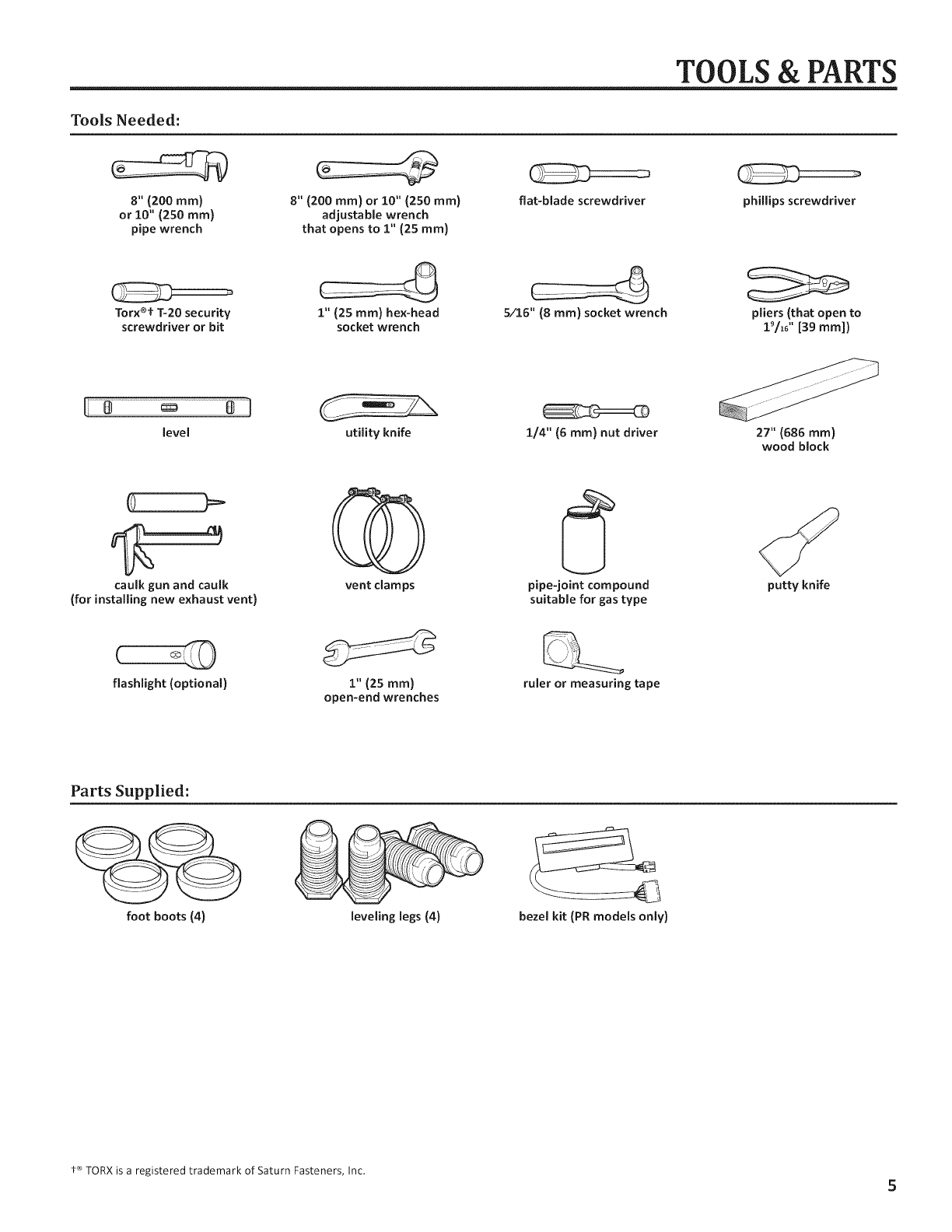
TOOIS
&
Parts
...ccsccsesscsseceeeeeeeeeessssssesassseeedeeeeeeeeeeeeeeeesesseeeaaaaes
5
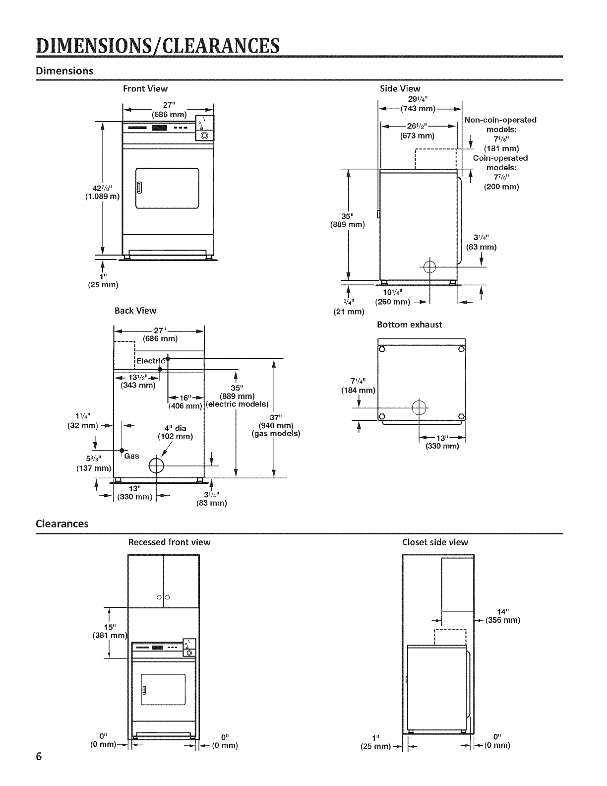
Dirmensions/CI@ArANCes
.occccccccccccceceessssessseeccanseceeteceensesteess
6
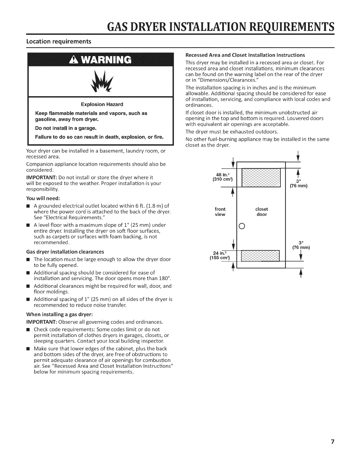
Gas
Dryer
Installation
Requirements
.......cccccccssssssssssseeseeeeees
7
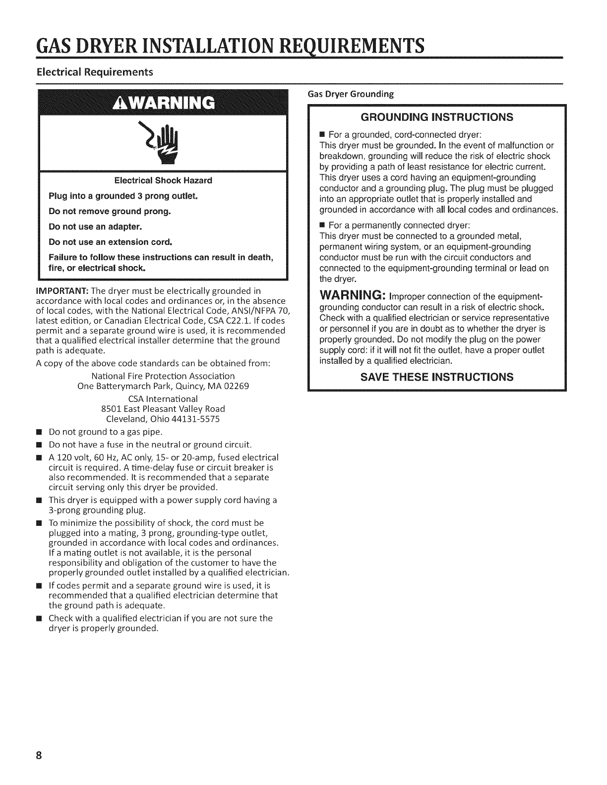
Electric
Dryer
Installation
Requirements
....cccccccccecsseeeeeees
10
Dryer
Venting
Requirement
........:ccccceeseceeeeeeeeeseeeeeeeeeesseees
13
Gas
Supply
CONNECTION
00.
ccccccccccsseeeeeeeeeseeeseeeseeeeeeeeeeeeeeeees
15
Installing
Leveling
LegS
......:::ccsssssseeeeeeeeeeceeeeeeeeeeeseeeeseeeseeees
17
Electric
Dryer
Electrical
COMMECTIONS
.....ccccccccesssseseeeseeeeeeees
18
LOVGHIIG
....ccccccccssscceccccasseccncccaaucccnaeceenecceaassenseecauseeesaseauasces
22
Complete
INStalation
.....cccccssssssessseeeeeeeeeseseeseeeeeeneeeeseeeseeees
23
Reversing
Dryer
Door
SWING
......c:ccccccceseeceeeeeeesseeeeeeeeeeseseees
24
Maintenance
Instructions
.......cccccsccceeeeeeeeeeeeeeeeeeeeeeeseseeeeees
25
If
You
Need
ASSISTANCE
.....ccccccsessseeeeeeeeeeeeeeeeeeeeeeeeeeeeeeeneeeeees
25
Electronic
Control
Setup
INStructions
.....cccccccccsssssseeseeeeeeees
26
Warranty
..ccccocsecccsssccsssesonsesonsnscnsaseessescasescasaseasaseesausesanauss
31
W10184578B
W10184579B
—
SP
INSTALLATION
INSTRUCTIONS
Commercial
Dryer
Gas
or
Electric
INSTRUCTIONS
D'
INSTALLATION
Sécheuse
a
usage
commercial
a
gaz
ou
électrique
TABLE
DES
MATIERES
Page
SEcurité
de
la
sECHGUSE
......cccccececessssesssnnnancacceeseeesseetseessaaes
32
Outils
Ct
PI@COS
...ececcccsssseensseseseeeeeeeeeeseseeeeeannssseeeeeeeeeeeeeeeees
35
Dimensions/Distances
de
dégagement
........:.:csessseeceseeeeeee
36
Exigences
d’installation
pour
la
sécheuse
@
BaZ.....cccsccseeeeees
37
Exigences
d’installation
pour
la
sécheuse
électrique
.........
40
Exigences
concernant
l’évacuation
de
la
sécheuse
......000:
42
Raccordement
a
la
canalisation
de
Baz
......ccssssssssnssscnseeesees
44
Installation
des
pieds
de
nivelleMment
........ccssssssssssssecsseeesees
46
Nivell@ment
.......ccccccccceeeeeeseeeeeeessessseeeeeeeeeesssseseeseeaaeeeeeeeeeeees
46
Achever
Vinstallation
.........ccccssccsssscssssnsscensseeseeesseesseessssnanaes
47
Inversion
du
sens
d’ouverture
de
la
POrte
......ccsssssssssseeseseees
48
INStFUCTIONS
C’ANTPETION
0.0...
ccsccssscccsccessesssesssssnsssnnsecanaseeesees
49
Si
vous
avez
besoin
d’assistance
.......csssssccsscesseessessssessssenaes
49
Instructions
de
réglage
du
tableau
de
commande
Electronique
......ccsssssssssccsccesssssseessssssssseaases
50
CE)
ga
| 6 |
ee
56
www.maytagcommerciallaundry.com