Maytag Amana AVZC18 Guide

Service and Troubleshooting
Copyright © 2021 Goodman Manufacturing Company, L.P.
RS6215003r1
July 2021
®
is a registered trademark of Maytag Corporation or its related companies and is used under license.
All rights reserved.
TABLE OF CONTENTS
IMPORTANT INFORMATION......................................... 2
PRODUCT IDENTIFICATION ........................................ 4
SYSTEM OPERATION................................................... 5
SERVICING.................................................................... 9
CHECKING VOLTAGE ................................................. 9
CHECKING WIRING ..................................................... 9
CHECKING THERMOSTAT, WIRING .......................... 9
THERMOSTAT AND WIRING....................................... 9
CHECKING TRANSFORMER AND CONTROL
CIRCUIT......................................................................... 9
CHECKING HIGH PRESSURE SWITCH .................. 10
CHECKING INDOOR AND OUTDOOR HI/LOW
PRESSURE SENSOR................................................. 10
CHECKING COMPRESSOR ...................................... 10
COMPRESSOR WINDING INSULATION TEST....... 11
GROUND TEST........................................................... 11
TESTING TEMPERATURE SENSORS AND EEV
COIL RESISTANCE..................................................... 12
TESTING EEV COIL RESISTANCE .......................... 12
TESTING REVERSING VALVE.................................. 12
AVPEC* HEATER CONTROL..................................... 13
NETWORK TROUBLESHOOTING............................ 13
REFRIGERATION REPAIR PRACTICE .................... 14
LEAK TESTING (NITROGEN OR
NITROGEN-TRACED) ................................................ 14
STANDING PRESSURE TEST (RECOMMENDED). 15
EVACUATION .............................................................. 15
CHARGING.................................................................. 16
FINAL CHARGE ADJUSTMENT ................................ 16
CHECKING COMPRESSOR EFFICIENCY .............. 16
CHECKING SUBCOOLING ........................................ 17
NON-CONDENSABLES.............................................. 17
COMPRESSOR BURNOUT ....................................... 18
REFRIGERANT PIPING ............................................. 18
Pride and workmanship go into every product to provide
our customers with quality products. It is possible, however,
that during its lifetime a product may require service.
Products should be serviced only by a qualied service
technician who is familiar with the safety procedures
required in the repair and who is equipped with the proper
tools, parts, testing instruments and the appropriate service
manual.
For service information related to the Bluetooth® Shared
Data Loader BTSDL01 referenced in this manual, please
refer to the installation instructions for the BTSDL01 at
www.coolcloudhvac.com/loaderuserguide

IMPORTANT INFORMATION
2
Pride and workmanship go into every product to provide our
customers with quality products. It is possible, however, that
during its lifetime a product may require service. Products
should be serviced only by a qualied service technician who
is familiar with the safety procedures required in the repair
and who is equipped with the proper tools, parts, testing in-
struments and the appropriate service manual.
OUTSIDE THE U.S., .
(Not a technical assistance line for dealers.) Your telephone company will bill you for the call.
While these items will not cover every conceivable situa-
tion, they should serve as a useful guide.
•
•
•
•
DUCT STATIC PRESSURES AND/OR STATIC
PRESSURE DROP ACROSS COILS ........................ 22
AIR HANDLER EXTERNAL STATIC.......................... 22
COIL STATIC PRESSURE DROP.............................. 22
INDOOR UNIT TROUBLESHOOTING ...................... 23
DIAGNOSTIC CODES ................................................ 25
AIR HANDLER TROUBLESHOOTING MATRIX....... 26
AIR HANDLER DISPLAY............................................ 28
SETTING THE MODE DISPLAY ................................ 36
7 - SEGMENT DISPLAY.............................................. 42
TROUBLESHOOTING ................................................. 45
WIRING DIAGRAMS.................................................... 58
ACCESSORIES ........................................................... 60
CHECKING HEATER LIMIT CONTROL(S)
(OPTIONAL ELECTRIC HEATERS) ......................... 61
ELECTRIC HEATER OPTIONAL ITEM ..................... 61
CHECKING HEATER FUSE LINK (OPTIONAL
ELECTRIC HEATERS)................................................ 62

IMPORTANT INFORMATION
3
When the outdoor unit is connected to main power, the
inverter board has a small current owing into it to be pre-
pared for operation when needed. Due to this, the Control
Board components have to be cooled even when the unit is
not running. For this cooling operation, the condenser fan
may come on at any time, including in the winter months.
Any obstruction to the outdoor fan should be avoided at all
times when the unit is powered to prevent damage.
The successful development of hermetically sealed refriger-
ation compressors has completely sealed the compressor’s
moving parts and electric motor inside a common housing,
minimizing refrigerant leaks and the hazards sometimes
associated with moving belts, pulleys or couplings.
Fundamental to the design of hermetic compressors is
a method whereby electrical current is transmitted to the
compressor motor through terminal conductors which pass
through the compressor housing wall. These terminals are
sealed in a dielectric material which insulates them from
the housing and maintains the pressure tight integrity of
the hermetic compressor. The terminals and their dielectric
embedment are strongly constructed, but are vulnerable
to careless compressor installation or maintenance pro-
cedures and equally vulnerable to internal electrical short
circuits caused by excessive system contaminants.
In either of these instances, an electrical short between the
terminal and the compressor housing may result in the loss
of integrity between the terminal and its dielectric embed-
ment. This loss may cause the terminals to be expelled,
thereby venting the vaporous and liquid contents of the
compressor housing and system.
A venting compressor terminal normally presents no dan-
ger to anyone, providing the terminal protective cover is
properly in place.
If, however, the terminal protective cover is not properly in
place, a venting terminal may discharge a combination of
a. hot lubricating oil and refrigerant
b. ammable mixture (if system is contaminated
with air)
in a stream of spray which may be dangerous to anyone in
the vicinity. Death or serious bodily injury could occur.
Under no circumstances is a hermetic compressor to be
electrically energized and/or operated without having the
terminal protective cover properly in place.
See Service Section for proper servicing.
•
•
•
•
•
•
•
•

PRODUCT IDENTIFICATION
4
A V Z C 18 036 1 AA
1 2 3 4 5,6 7,8,9 10 11,12
Brand Engineering *
A Amana® Brand Major/ Minor Revisions
* Not used for order or inventory control
Product Category
S Split System Electrical
V Inverter Split System 1 - 208/230 V, 1 Phase, 60 Hz
Unit Type Capacity
X Condenser R-410A 024 2 Tons 048 4 Tons
Z Heat Pump R-410A 036 3 Tons 060 5 Tons
C 16 16 SEER 18 18 SEER 20 20 SEER
Integrated Communica�ng ComfortBridge™ Technology
A V P E C 25 B 1 4 AA
123456,78 9 10 11,12
Brand Engineering*
ASingle-Piece Air Handler Major/Minor Revisions
*Notused for inventory management
Unit Applica�on Refrigerant Charge
R4= R-410A
S
VElectrical
1208/230V, 1 Phase, 60 Hz
Cabinet Finish Cabinet Width
UUnpainted B = 17½"
P Painted "12=C
D= 24½"
Expansion Device
EElectronic Expansion Valve Nominal Capacity @ 13 SEER
T Expansion Device 24 = 2 Tons31 = 2½ Tons48 = 4 Tons
V Inverter Tuned Expansion Valve 25 = 2 Tons36 = 3 Tons 49 =3-3½ Tons
29 = 2 Tons37 = 3½ Tons59 = 4-5 Tons
Communica�ng 30 = 2½ Tons42 = 3½ Tons60 = 5 Tons
C = Integrated Communica�ng ComfortBridge™
Technolgy
61 = 4-5 Tons

SYSTEM OPERATION
5
This section gives a basic description of heat pump con-
denser unit operation, its various components and their ba-
sic operation. Ensure your system is properly sized for heat
gain and loss according to methods of the Air Conditioning
Contractors Association (ACCA) or equivalent.
The ambient air is pulled through the heat pump con-
denser coil by a direct drive propeller fan. This air is then
discharged out of the top of the cabinet. These units are
designed for free air discharge, so no additional resistance,
like duct work, shall be attached.
The gas and liquid line connections on present models are
of the sweat type for eld piping with refrigerant type copper.
Front seating valves are factory installed to accept the eld
run copper. The total refrigerant charge for a normal installa-
tion is factory installed in the heat pump condenser unit.
AVZC18 models are available in 2 through 5 ton sizes and
use R-410A refrigerant. They are designed for 208/230 volt
single phase applications.
All AVZC18 models use a Daikin rotary compressor speci-
cally designed for R-410A refrigerant.
AVZC18 models use “FVC50K” which is NOT compatible
with mineral oil based lubricants like 3GS. “FVC50K” oil
(required by the manufacturer) must be used if additional oil
is required.
The refrigerant used in the system is R-410A. It is a clear,
colorless, non-toxic and non-irritating liquid. R-410A is a
50:50 blend of R-32 and R-125. The boiling point at atmo-
spheric pressure is -62.9°F.
A few of the important principles that make the refrigeration
cycle possible are: heat always ows from a warmer to a
cooler body. Under lower pressure, a refrigerant will absorb
heat and vaporize at a low temperature. The vapors may be
drawn o and condensed at a higher pressure and tem-
perature to be used again.
The indoor evaporator coil functions to cool and dehumidify
the air conditioned spaces through the evaporative process
taking place within the coil tubes.
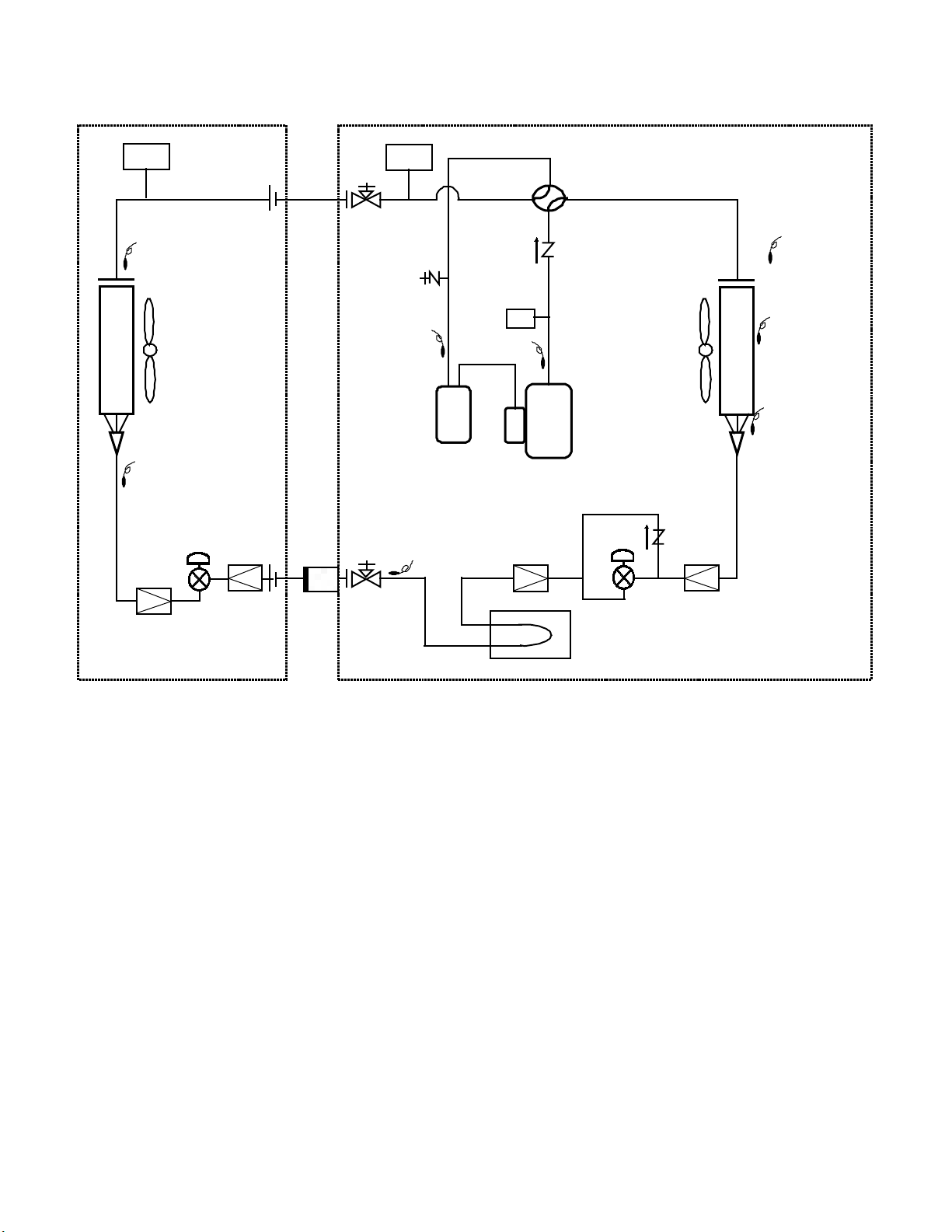
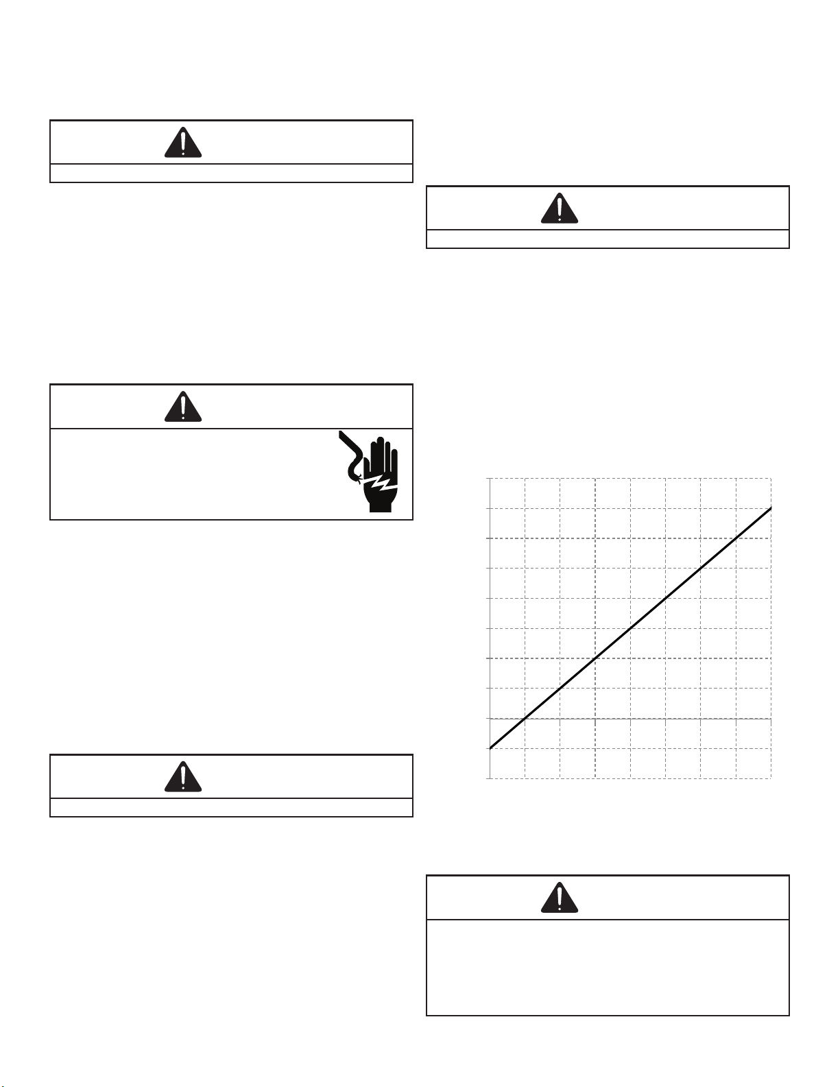
The pressures and temperatures shown in the
refrigerant cycle illustrations on the following pages are
for demonstration purposes only. Actual temperatures and
pressures are to be obtained from the “Expanded Perfor-
mance Chart”.
Liquid refrigerant at condensing pressure and temperatures
leaves the outdoor condensing coil through the drier and is
metered into the indoor coil through indoor electronic ex-
pansion valve. As the cool, low pressure, saturated refriger-
ant enters the tubes of the indoor coil, a portion of the liquid
immediately vaporizes. It continues to soak up heat and
vaporizes as it proceeds through the coil, cooling the indoor
coil down to about 48°F.
Heat is continually being transferred to the cool ns and
tubes of the indoor evaporator coil by the warm system air.
This warming process causes the refrigerant to boil. The
heat removed from the air is carried o by the vapor.
As the vapor passes through the last tubes of the coil, it
becomes superheated. That is, it absorbs more heat than is
necessary to vaporize it. This is assurance that only dry gas
will reach the compressor. Liquid reaching the compressor
can weaken or break compressor valves.
The compressor increases the pressure of the gas, thus
adding more heat, and discharges hot, high pressure super-
heated gas into the outdoor condenser coil.
In the condenser coil, the hot refrigerant gas, being warmer
than the outdoor air, rst loses its superheat by heat trans-
ferred from the gas through the tubes and ns of the coil.
The refrigerant now becomes saturated, part liquid, part va-
por and then continues to give up heat until it condenses to
a liquid alone. Once the vapor is fully liqueed, it continues
to give up heat which subcools the liquid, and it is ready to
repeat the cycle.
The inverter system can stop the compressor or outdoor
fan to protect the unit. The inverter system can run higher
compressor speed than required from thermostat to recover
compressor oil that ows.
The heating portion of the refrigeration cycle is similar to the
cooling cycle. By de-energizing the reversing valve solenoid
coil, the ow of the refrigerant is reversed. The indoor coil
now becomes the heat pump condenser coil, and the out-
door coil becomes the evaporator coil. The check valve at
the outdoor coil will be forced closed by the refrigerant ow,
thereby utilizing the outdoor expansion device. An electron-
ic expansion valve meters the condensed refrigerant to the
outdoor coil.
The defrosting of the outdoor coil is controlled by the PCB
and the outdoor coil temperature thermistor and defrost
sensor. The outdoor coil temperature thermistor (Tm)
sensor is clamped to a return bend entering the outdoor
coil and the defrost sensor at bottom owrator leg at
outdoor coil outlet. Defrost timing periods of 30, 60, 90 or
120 minutes may be selected via the thermostat setting.
PCB will initiate time defrost at the interval selected from
the thermostat. During operation, the microprocessor on
the PCB checks the coil and defrost temperature (Tm and
Tb) via sensors every 5 seconds in heating mode. When
the PCB detects the coil temperature to be high enough
(approximately 54°F) and defrost sensor more than 43°F for
30 seconds, the defrost cycle is terminated and the timing
period is reset.

SYSTEM OPERATION
6
A system verication test is now required to check the
equipment settings and functionality.
18 SEER Inverter units are tested by any of the following
methods:
• Setting the “SUt” menu (System verication test) to ON
through the indoor unit control board push buttons.
• Setting the System verication test menu of mode
display screen-4 to ON through the outdoor unit con-
trol board push buttons.
Once selected, it checks the equipment for approximately 5
- 15 minutes. System test may exceed 15 minutes if there is
an error. Refer to the Troubleshooting section, if error code
appears.
Before starting the SYSTEM TEST, turn o the electric
heater (if applicable)
If the unit is attempting to run SYSTEM TEST in
under 20°F ambient temperature, the unit may not be able
to complete the test due to low suction pressure. In such a
case, re-run the SYSTEM TEST when the ambient tem-
perature exceeds 20°F.
CHARGE mode allows for charging of the system.
System operates for a duration of approximately one hour
while the equipment runs at full capacity.
After one hour, the CHARGE MODE ends and the system
resumes normal operation.
Before starting the CHARGE MODE, turn o the Cool or
Heat mode and electric heat (if applicable).
a. 18 SEER Inverter units are charged by any of the fol-
lowing methods:
• setting the “CR9” menu (Charge Mode) to ON
through the indoor unit control board push buttons.
• setting the Charge mode menu of mode display
screen-4 to ON through the outdoor unit control board
push buttons.
• Through the CoolCloud HVAC phone application.
b. The System will remain in charge mode (high speed)
for 60 minutes before timing out.
c. Manually shut o.
BOOST MODE enables the system to operate at a higher
compressor speed than rated maximum compressor speed
and satisfy the structural load more eectively during higher
ambient outdoor conditions. BOOST MODE is initiated by
an outdoor temperature sensor located in the outdoor unit.
Please note that outdoor equipment operational sound lev-
els may increase while the equipment is running in BOOST
MODE. Disabling BOOST MODE will provide the quietest
and most ecient operation.
For regions with high humidity, it is strongly recom-
mend to use a thermostat with humidity sensor and dehu-
midication terminal.
Without this type of thermostat, dehumidication operation
does not work.
Dehumidication requires a thermostat capable of reading
the indoor humidity level and allowing the user to set a
dehumidication target.
The thermostat controls the humidity level of the condi-
tioned space using the cooling system. Dehumidication
is engaged whenever a cooling demand is present and
humidity levels are above the target level.
When this condition exists, the circulating fan output is re-
duced, increasing system run time, over cooling the evap-
orator coil and ultimately removing more humidity from the
structure than if only in cooling mode.
The thermostat may also allow for an additional overcool-
ing limit setting depending on the thermostat utilized. This
allows the cooling system to further reduce humidity by
lowering the temperature below the cooling setpoint in an
attempt to better achieve desired humidity levels.
For eective dehumidication operation:
• Ensure “Dehumidication selection” is NOT set to
“OFF”.
• Verify the cooling airow prole is set to “Prole D”.
- See the Cool Set-up section of the Installation
Manual for complete airow prole details.
- By default, “Dehumidication selection” is standard
and the cooling airow prole is set to “Prole D”.
• For additional dehumidication control, airow set-
tings are eld adjustable and can be ne-tuned to a
value that is comfortable for the application from a
range of Cool Airow Trim.
OVERVIEW
The ComfortBridge based inverter heating and air condi-
tioning system uses an indoor unit and outdoor unit digitally
communicating with one another via a two-way communi-
cations path. ComfortBridge is compatible with any 24 VAC
single stage thermostat which send inputs to the indoor unit.

SYSTEM OPERATION
7
The ComfortBridge system permits access to system in-
formation, advanced set-up features, and advanced diag-
nostic/troubleshooting features via the control board push
buttons or the CoolCloud HVAC app.
The heat pump’s diagnostics menu provides access to the
most recent faults. The six most recent faults can be ac-
cessed through the control board seven segment displays.
Any consecutively repeated fault is stored a maximum of
three times.
A leak in the system, low refrigerant charge
or an incompletely open stop valve can cause the unit to
ash error code E15. This error code suggests that the unit
is experiencing operation at low pressure. The control will
only store this fault the rst three consecutive times the fault
occurs.
The fault list can be cleared after performing mainte-
nance or servicing the system to assist in the troubleshoot-
ing process.
This menu displays information about the systems current
status. This menu can be utilized to conrm correct func-
tionality of the equipment and for troubleshooting purposes.
The following items will be displayed:
• Heat Capacity Request Percentage
• Cool Capacity Request Percentage
• Heat Capacity Request During Defrost Percentage
• Dehumidication Request Percentage
• Reversing Valve Status
• Reported Airow by Indoor Unit
• Boost Mode
• Previous Defrost Run Time
The following sensor values will be displayed:
• Outdoor Temperature
• Coil Temperature
• Liquid Line Temperature
• Discharge Temperature
• Defrost Sensor
• Suction Pressure
This function can be enabled in this menu.
The system allows for the adjustment of several cooling
performance variables. Cool Airow Trim (*1), Cool Airow
Proles, Cool Fan ON Delay, Cool Fan OFF Delay and
Dehumidication Select (some enable option or o) can be
adjusted in this menu. You can also reset this entire menu
to factory default settings. See the following images show-
ing the four cooling airow proles.
For regions with high humidity, it is strongly rec-
ommend to use a thermostat with humidity sensor and
dehumidication terminal. Without this type of thermostat,
dehumidication operation does not work.
Dehumidication requires a thermostat capable of reading
the indoor humidity level and allowing the user to set a
dehumidication target.
The thermostat controls the humidity level of the condi-
tioned space using the cooling system. Dehumidication
is engaged whenever a cooling demand is present and
humidity levels are above the target level.
When this condition exists, the circulating fan output is re-
duced, increasing system run time, over cooling the evap-
orator coil and ultimately removing more humidity from the
structure than if only in cooling mode.
The thermostat may also allow for an additional overcool-
ing limit setting depending on the thermostat utilized. This
allows the cooling system to further reduce humidity by
lowering the temperature below the cooling setpoint in an
attempt to better achieve desired humidity levels.

SYSTEM OPERATION
8
Stop Valve
(Liquid)
Stop
Valve
(Ga s )
Fan
Motor
HP/LP
OD HP/LP
Sensor
Check Valve
HPS
Outdoor Unit
Indoor Unit
Cooling
EEV
Td
Th e r m i s t or
Tm
Th e r m i s t or
Tb
Th e r m i s t or
Ta
Th e r m i s t or
Tl
Th e r m i s t or
SubACC
Motor
Check Valve
Reversing Valve
EEV
Filter
Filter
Fan
ACC
Comp
Ts
Th e r m i s t or
Filter
Tli
Th e r m i s t or
Tgi
Th e r m i s t or
HP/LP
ID HP/LP
Sensor
Filter Dryer
Acce s s Tube
Filter
LEGEND:
Tl = Thermistor (Outdoor Liquid Temperature)
Td = Thermistor (Discharge Temperature)
Tb = Thermistor (Defrost Sensor)
Tm = Thermistor (Outdoor Coil Temperature)
Ta = Thermistor (Outdoor Air Temperature)
Tgi = Thermistor (Indoor Gas Temperature)
Tli = Thermistor (Indoor Liquid Temperature)
Ts = Thermistor (Suction Temperature)
OD HP/LP sensor = Outdoor High/Low Pressure Sensor
ID HP/LP sensor = Indoor High/Low Pressure Sensor
HPS = High Pressure Switch

SERVICING
9
1. Remove outer case, control panel cover, etc., from
unit being tested.
With power ON:
2. Using a voltmeter, measure the voltage across ter-
minals L1 and L2 of the contactor for the heat pump
condenser unit or at the eld connections for the air
handler or heaters.
Measure the voltage across the L1 and L2 lugs on the
unitary (UC) control.
3. No reading - indicates open wiring, open fuse(s) no
power or etc., from unit to fused disconnect service.
Repair as needed.
4. With ample voltage at line voltage connectors, ener-
gize the unit.
Vol tage Min. Max
208/230 197 253
Unit Supply Voltage
: When operating electric heaters on voltages other
than 240 volt, refer to the System Operation section on
electric heaters to calculate temperature rise and air ow.
Low voltage may cause insucient heating.
1. Check wiring visually for signs of overheating, dam-
aged insulation and loose connections.
2. Use an ohmmeter to check continuity of any suspect-
ed open wires.
3. If any wires must be replaced, replace with compara-
ble gauge and insulation thickness.
Communicating Thermostat Wiring: The maximum wire
length for 18 AWG thermostat wire is 250 feet.
With power ON, thermostat calling for cooling/heating.
1. Use a voltmeter to check for 24 volt at thermostat
wires C and R in the indoor unit control panel.
2. No voltage indicates trouble in the thermostat, wiring
or transformer source.
3. Check the continuity of the thermostat and wiring.
Repair or replace as necessary.
With power ON:
1. Set room thermostat to a higher setting than room
temperature so both stages call for heat.
2. With voltmeter, check for 24 volt at each heater relay.
3. No voltage indicates the trouble is in the thermostat
or wiring.
4. Check the continuity of the thermostat and wiring.
Repair or replace as necessary.
Consideration must be given to how the heaters
are wired (O.D.T. and etc.). Also safety devices must be
checked for continuity.
A step-down transformer (208/230 volt primary to 24 volt
secondary) is provided with each indoor unit. This allows
ample capacity for use with resistance heaters. The outdoor
sections do not contain a transformer (See note below).
(See indoor unit WIRING DIAGRAM).

SERVICING
10
1. Remove control panel cover, or etc., to gain access to
transformer.
With power ON:
2. Using a voltmeter, check voltage across secondary
voltage side of transformer (R to C).
3. No voltage indicates faulty transformer, bad wiring, or
bad splices.
4. Check transformer primary voltage at incoming line
voltage connections and/or splices.
5. If line voltage available at primary voltage side of
transformer and wiring and splices good, transformer
is inoperative. Replace.
The high pressure switch senses the pressure in the com-
pressor discharge line. If abnormally high condensing pres-
sures develop, the contacts of the control open, breaking
the control circuit before the compressor motor overloads.
This control is automatically reset.
1. Using an ohmmeter, check across the X32A connec-
tion on the outdoor unit PCB terminals of high pres-
sure control, with wire removed. If not continuous, the
contacts are open.
2. Attach a gauge to the dill valve port on the base
valve.
With power ON:
3. Start the system in charge mode and place a piece
of cardboard in front of the outdoor coil, raising the
condensing pressure.
4. Check pressure at which the high pressure control
cuts-out. If it cuts-out at 605 PSIG to -17 PSIG, it is
operating normally (See causes for high head pres-
sure in Service Problem Analysis Guide). If it cuts out
below this pressure range, replace the control.
The HI/LOW pressure sensor senses the suction pressure in
cooling mode, and the discharge pressure in heating mode.
Follow the following sequence to check the pressure sensor.
With Power ON:
1. Connect manifold gauge to the air conditioner unit
2. Connect a pair of extended Molex probe tips to your
voltmeter test leads.
3. Find the suction pressure in the cool mode, or dis-
charge pressure in the heat mode (terminals) Locate
(X17A) connection and connect a DC voltmeter
across sensor terminals 1 and 3, (black and white
wires) and record the DC voltage.
4. Compare your readings to the detected pressure vs
output voltage in the following table. Replace the
sensor if the sensor is open, shorted, or outside of the
voltage range.
-200
-100
0
100
200
300
400
500
600
700
800
0.0 0.5 1.0 1.5 2.0 2.5 3.0 3.5 4.0
Detected Pressure (PSIG)
Output Voltage (DCV)
VOLTAGE AND PRESSURE CHARACTERISTICS

SERVICING
11
If the compressor terminal PROTECTIVE COVER and
gasket (if required) are not properly in place and secured,
there is a remote possibility if a terminal vents, that the
vaporous and liquid discharge can be ignited, spouting
ames several feet, causing potentially severe or fatal injury
to anyone in its path.
This discharge can be ignited external to the compressor if
the terminal cover is not properly in place and if the
discharge impinges on a sucient heat source.
Ignition of the discharge can also occur at the venting
terminal or inside the compressor, if there is sucient
contaminant air present in the system and an electrical arc
occurs as the terminal vents.
Ignition cannot occur at the venting terminal without the
presence of contaminant air, and cannot occur externally
from the venting terminal without the presence of an
external ignition source.
Therefore, proper evacuation of a hermetic system is
essential at the time of manufacture and during servicing.
To reduce the possibility of external ignition, all open ame,
electrical power, and other heat sources should be
extinguished or turned o prior to servicing a system.
The Inverter on the outdoor control board takes the position
signal from the UVW line, connected with the compressor.
If the system detects a malfunction on the compressor,
check the insulation resistance in accordance with the fol-
lowing procedure.
1. Remove the leads from the compressor terminals.
2. Using a Megometer, attach one lead to ground.
3. Using the other lead of the Megometer, check the
insulation between U to ground, V to ground, W to
ground.
Compressor
Terminal
Unpainted
Refrigerant
Piping
TESTING COMPRESSOR WINDINGS INSULATION
The 2, 3, and 4 ton compressor has a terminal on
the top. The 5 ton compressor has the terminals on the
side. If the insulation resistance of the compressor is less
than 100k Ohms between U to ground, V to ground, W to
ground, replace the compressor.
If fuse, circuit breaker, ground fault protective device, etc.,
has tripped, this is a strong indication that an electrical
problem exists and must be found and corrected. The circuit
protective device rating must be checked, and its maximum
rating should coincide with that marked on the equipment
nameplate.
With the terminal protective cover in place, it is acceptable
to replace the fuse or reset the circuit breaker ONE TIME
ONLY to see if it was just a nuisance opening. If it opens
again, DO NOT continue to reset.
making sure that all power
legs are open.
1. DO NOT remove protective terminal cover. Discon-
nect the three leads going to the compressor termi-
nals at the nearest point to the compressor.
2. Identify the leads and using an ohmmeter on the R x
10,000 scale or the highest resistance scale on your
ohmmeter check the resistance between each of the
three leads separately to ground (such as an unpaint-
ed tube on the compressor).
3. If a ground is indicated, then carefully remove the
compressor terminal protective cover and inspect for
loose leads or insulation breaks in the lead wires.
4. If no visual problems indicated, carefully remove the
leads at the compressor terminals.
5. Carefully retest for ground, directly between compres-
sor terminals and ground.
6. If ground is indicated, replace the compressor. The
resistance reading should be innity. If there is any
reading on meter, there is some continuity to ground
and compressor should be considered defective.

SERVICING
12
The AVZC ready heat pump models and AVPEC indoor
units are factory equipped with:
• (Ta) an outdoor air temperature sensor
• (Tm) an outdoor coil temperature sensor
• (TI) an outdoor liquid temperature sensor
• (Td) a discharge temperature sensor
• (Tb) a defrost temperature sensor
• (Tgi) an indoor gas temperature sensor
• (Tli) an indoor liquid temperature sensor
To check above sensors:
1. Disconnect power to the heat pump condensor.
2. Disconnect the sensor from the electric board.
3. Connect an ohmmeter across the sensor terminals.
The ohmmeter should read be the resistance shown
in the table THERMISTOR RESISTANCE AND
TEMPERATURE CHARACTERISTICS. Replace the
sensor if the sensor is open, shorted, or outside the
valid resistance range.
To check the resistance of the EEV coil, rst disconnect
EEV cable from the Control board. Make measurements of
resistance between the connector pins, and then make sure
the resistance falls in the range of 40 to 50Ω.
CHECKING REVERSING VALVE AND SOLENOID
Reversing valve used in heat pumps could potentially leak
internally. Discharge gases can leak into the suction inside
the valve. Compound gages will give the same symptoms
as bad compressor valves or broken scroll anks. The
temperature between true suction and the suction line after
the valve should not be greater than 4 degrees. The
center tube is always the suction line and should be cold.
TROUBLESHOOTING THE REVERSING VALVE FOR
ELECTRICAL FAILURE
Place unit into the cooling mode. Test for 24 volts at the
solenoid. If there is no voltage present at coil, check the
control voltage. If voltage is present, loosen the nut on the
top of the coil. Remove the coil, there should be slight resis-
tance. If the slight resistance is felt, remove the coil. As you
remove the coil listen carefully, an audible click should be
detected. The clicking is due to the movement of the pilot
valve plunger. The absence of a clicking sound indicates
the plunger is stuck.
TROUBLESHOOTING MECHANICAL FAILURES ON A
REVERSING VALVE BY PRESSURE
Troubleshooting the reversing valve can be done by pres-
sure and touch. Raise the head pressure. In the cooling
mode block the fan exhaust. Once head pressure has been
raised, cycle between cooling and heating and see if the
piston can be freed.
TROUBLESHOOTING MECHANICAL FAILURES ON A
REVERSING VALVE BY TEMPERATURE
When operating properly the valve contains refrigerant
gases at certain temperatures. The discharge line should be
the same temperature after the valves discharge line.

SERVICING
13
The true suction should be the same as the suction line
after the valve. If there is a 4-degree dierence, valve is
leaking. When stuck in the mid-position, part of the dis-
charge gas from the compressor is directed back to the
suction side, resulting in excessively high suction pressure.
An increase in the suction line temperature through the
reversing valve can also be measured. Check operation of
the valve by starting the system and switching the opera-
tion from COOLING to HEATING cycle. If the valve fails to
change its position, test the voltage (24V) at the valve coil
terminals (X25A) on outdoor unit PCB while the system is
on the COOLING cycle. If voltage is registered at the coil,
tap the valve body lightly while switching the system from
HEATING to COOLING, etc. If this fails to cause the valve
to switch positions, remove the coil connector cap and test
the continuity of the reversing valve solenoid coil. If the coil
does not test continuous - replace it. If the coil test continu-
ous and 24 volts is present at the coil terminals, the valve is
inoperative - replace it.
DESCRIPTION
The AVPEC* models utilize an electronic control that pro-
vides ECM blower motor control and control of up to two
electric heat sequencers. The control has thermostat inputs
for variable stage of cooling/heating, two stages of electric
heat, reversing valve, and dehumidication. Control input is
24 VAC.
FEATURES
The new air handler control includes advanced diagnostic
features with fault recall, estimated CFM display via 7
segment display of control board, CoolCloudTM ready.
Diagnostics includes heater kit selection diagnostics, open
fuse, internal control fault, data errors, and blower motor
faults. Data errors are not included in the fault recall list.
Diagnostic error codes are displayed on a single red LED.
The estimated CFM is displayed on an on-board 7 segment
display. For example, if the CFM is 1240 CFM, 7 segment
display shows “FC...A...12...40...”.
The AVPEC* air handlers may be used in a fully communi-
cating system when matched with a compatible outdoor unit
and the thermostat. A fully communicating system oers
advanced setup and diagnostic features.
BASIC OPERATION
The air handler control receives operation demand inputs
from the thermostat. The control operates the variable
speed blower motor at the demand as determined from the
thermostat input(s). If a demand for electric heat is re-
ceived, the control will provide a 24VAC output for up to two
electric heat contactors.
MOTOR CONTROL CIRCUITS
1. Turn on power to air handler or modular.
2. Check voltage between pins 1 and 4 at the 4-wire
motor connector on the control board. Voltage should
be between 9 and 15 VDC. Replace control if voltage
is not as specied.
ELECTRIC HEAT SEQUENCER OUTPUTS
1. Turn on power to air handler or modular blower.
2. Disconnect the 3-circuit harness connecting the con-
trol to the electric heater kit.
3. Provide a thermostat demand for low stage auxiliary
heat (W1). Measure the voltage between pins 1 and
3 at the on-board electric heat connector. Voltage
should measure 24VAC. Replace control if no voltage
is present.
Allow for any built-in time delays before making
voltage measurements. Any electric heater faults that are
present may prevent the heater output from energizing. Ver-
ify that no heater faults are present before making voltage
measurements.

SERVICING
14
Communications is achieved by taking the dierence
between a positive dc signal and a negative dc signal. The
positive dc signal is termed “data 1” or “1”. Data 1 is positive
with respect to ground (or common). The negative dc signal
is termed “data 2” or “2”. Data 2 is negative with respect
to ground (or common). Data 1 should be approximately
2.8 volts dc. Data 2 should be approximately 2.2 volts dc.
The voltage dierence between data 1 and data 2 should
be approximately 0.6 volts dc. Verify that the bus DS1 dip
switches are in the ON position.
The integrated air handler control has some on-board tools
that may be used to troubleshoot the network. These tools
are: red communications LED, green receive (Rx) LED, and
learn button. These are described below
a. Red communications LED – Indicates the status
of the network. Refer to the Network Trouble-
shooting Chart for the LED status and the corre-
sponding potential problem.
b. Green receive LED – Indicates network trac.
Refer to the Network Troubleshooting Chart for
the LED status and the corresponding potential
problem.
c. Learn button – Used to reset the network. De-
press the button for approximately 2 seconds to
reset the network.
Voltages between the two data lines and between each
data line and common may be used to determine if the
network is operating properly.
Do the following to measure the voltages on the communi-
cations data lines.
1. With power on to the unit, measure voltage between
terminal “1” and terminal “C” on control board’s ther-
mostat connector. Voltage should be as noted in the
table below.
2. Measure voltage between terminals “2” and “C”.
3. Measure voltage between terminals “1” and “2”.
4. If voltages are dierent than stated in the table below,
check thermostat wiring for opens/shorts.
5. The network troubleshooting chart provides additional
communications troubleshooting information.
1 to C > 2.5 Vdc
2 to C < 2.5 Vdc
1 to 2 > 0.2 Vdc
When repairing the refrigeration system:
1. Never open a system that is under vacuum. Air and
moisture will be drawn in.
2. Plug or cap all openings.
3. Remove all burrs and clean the brazing surfaces of
the tubing with sand cloth or paper. Brazing materials
do not ow well on oxidized or oily surfaces.
4. Clean the inside of all new tubing to remove oils and
pipe chips.
5. When brazing, sweep the tubing with dry nitrogen to
prevent the formation of oxides on the inside surfaces.
6. Complete any repair by replacing the liquid line drier
in the system, evacuate and charge.
BRAZING MATERIALS
Torch heat required to braze tubes of
various sizes is proportional to the size of the tube. Tubes
of smaller size require less heat to bring the tube to brazing
temperature before adding brazing alloy. Applying too much
heat to any tube can melt the tube. Service personnel must
use the appropriate heat level for the size of the tube being
brazed.
The use of a heat shield when brazing is recom-
mended to avoid burning the serial plate or the nish on the
unit. Heat trap or wet rags should be used to protect heat
sensitive components such as stop valves, EEV, TXV and
lters.
Copper to Copper Joints - Sil-Fos used without ux (alloy
of 15% silver, 80% copper, and 5% phosphorous). Recom-
mended heat 1400°F.
Copper to Steel Joints - Silver Solder used without a ux
(alloy of 30% silver, 38% copper, 32% zinc). Recommended
heat - 1200°F.

SERVICING
15
Pressure test the system using dry nitrogen and soapy wa-
ter to locate leaks. If you wish to use a leak detector, charge
the system to 10 PSIG using the appropriate refrigerant
then use nitrogen to nish charging the system to working
pressure, then apply the detector to suspect areas. If leaks
are found, repair them. After repair, repeat the pressure
test. If no leaks exist, proceed to system evacuation.
Best practices dictate system should be pressure tested
at 450 PSIG with nitrogen for a minimum 4 hours. Follow
the procedure outlined below to test system. If leaks are
found, repair them. After repair, repeat the leak pressure
test described above. If no leaks exist, proceed to system
evacuation and charging.
SYSTEM PRESSURE TESTING
Once all of the refrigerant line connections are completed.
Perform a 3-step nitrogen pressure test.
1. Pressurize the system with nitrogen to 150 PSIG and
hold for 3 minutes. If any pressure drops occur, locate
and repair leaks and repeat step 1.
2. Pressurize the system with nitrogen to 325 PSIG and
hold for 5 minutes. If any pressure drops occur, locate
and repair leaks and repeat step 1.
3. Pressurize the system with nitrogen to 450 PSIG and
hold for 4 hours. If any pressure drops occur, locate
and repair leaks and repeat step 1.
IMPORTANT NOTE: Because of the potential damage to
compressors, do not allow suction pressure at service valve
to drop below 5 PSIG when pumping unit system down for
repair. Outdoor section, depending on line set length and
amount of charge in system, may not be able to hold the
entire system charge.
This is the most important part of the entire service proce-
dure. The life and eciency of the equipment is dependent
upon the thoroughness exercised by the serviceman when
evacuating air (non-condensables) and moisture from the
system.
Air in a system causes high condensing temperature and
pressure, resulting in increased power input and reduced
performance.
Moisture chemically reacts with the refrigerant oil to form
corrosive acids. These acids attack motor windings and
parts, causing breakdown.
The equipment required to thoroughly evacuate the system
is a vacuum pump, capable of producing a vacuum equiva-
lent to 500 microns absolute and a micron gauge to give a
true reading of the vacuum in the system.
Never use the system compressor as a vacuum
pump or run when under a high vacuum. Motor damage
could occur.
The triple evacuation method is recommended.
1. Evacuate the system to 4000 microns and hold for 15
minutes. Then, break the vacuum with dry nitrogen,
bring the system pressure up to 2-3 PSIG, and hold
for 20 minutes. Release the nitrogen.
2. Evacuate to 1500 microns and hold for 20 minutes.
Break the vacuum with dry nitrogen again, bring the
system pressure back up to 2-3 PSIG, and hold for 20
minutes.
3. Then, evacuate the system until it is below 500 mi-
crons and hold for 60 minutes.
1. Connect the vacuum pump, vacuum tight manifold set
with high vacuum hoses, micron gauge and charging
cylinder as shown.

SERVICING
16
2. Start the vacuum pump and open the shut o valve to
the high vacuum gauge manifold only. After the com-
pound gauge (low side) has dropped to approximately
29 inches of vacuum, open the valve to the vacuum
micron gauge. See that the vacuum pump will blank-o
to a maximum of 500 microns. A vacuum pump can only
produce a good vacuum if its oil is non-contaminated.
LOW SIDE
GAUGE
AND VALVE
HIGH SIDE
GAUGE
AND VALVE
TO
UNIT SERVICE
VALVE PORTS
VACUUM PUMP
VACUUM PUMP
ADAPTER
800 PSI
RATED
HOSES
CHARGING
CYLINDER
AND SCALE
EVACUATION
3. If the vacuum pump is working properly, close the
valve to the micron gauge and open the high and low
side valves to the high vacuum manifold set. With
the valve on the charging cylinder closed, open the
manifold valve to the cylinder.
4. Evacuate the system to at least 29 inches gauge
before opening valve to micron gauge.
5. Continue to evacuate to a maximum of 500 microns.
Close valve to vacuum pump and watch rate of rise.
If vacuum does not rise above 500 microns in three
to ve minutes, system can be considered properly
evacuated.
6. If micron gauge continues to rise and levels o at
about 2000 microns, moisture and non-condensables
are still present. If gauge continues to rise a leak is
present. Repair and re-evacuate.
7. Close valve to micron gauge and vacuum pump.
Shut o pump and prepare to charge.
•
•
Charge the system with the exact amount of refrigerant.
See the Installation Manual for the correct refrigerant
charge.
An inaccurately charged system will cause future problems.
1. When using an ambient compensated calibrated
charging cylinder, allow liquid refrigerant only to enter
the high side.
2. Once the system stops taking refrigerant, close the
valve on the high side of the charging manifold.
3. Start the system and charge the balance of the refrig-
erant through the low side.
R410A should be drawn out of the storage container
or drum in liquid form due to its fractionation properties, but
should be “Flashed” to its gas state before entering the sys-
tem. There are commercially available restriction devices
that t into the system charging hose set to accomplish this.
charge liquid R410A into the compressor.
4. With the system still running, close the valve on the
charging cylinder. At this time, you may still have
some liquid refrigerant in the charging cylinder hose
and will denitely have liquid in the liquid hose.
Reseat the liquid line core. Slowly open the high side
manifold valve and transfer the liquid refrigerant from
the liquid line hose and charging cylinder hose into
the suction service valve port. CAREFUL: Watch so
that liquid refrigerant does not enter the compressor.

SERVICING
17
The outdoor temperature must be 65°F to 105°F. If out-
door ambient temperature is out of range, charge dened
amount and don’t adjust subcooling. Set unit to CHARGE
mode.
After system has stabilized per startup instructions, check
subcooling as detailed in the following section.
In the event of system overcharge or undercharge, refriger-
ant in the system must be adjusted to the appropriate sub-
cooling and superheat as specied in the following sections.
Refrigerant amount should be adjusted within +/- 0.5 lb. if
the outdoor ambient temperature is greater than 65°F and
less than 105°F. Manufacturer recommends that the system
should be evacuated and should be charged the initial re-
frigerant for given line length when the ambient temperature
is less than 65°F and more than 105°F. Refer to the Installa-
tion Manual to calculate refrigerant amount.
5. With the system still running, remove hose and rein-
stall both valve caps.
6. Check system for leaks.
Subcooling information is valid only while the unit is
operating at 100% capacity or 100% of compressor speed
in CHARGE MODE. Compressor speed is displayed under
STATUS menu in the thermostat.
The reason for compressor ineciency is that the com-
pressor is broken or damaged, reducing the ability of the
compressor to pump refrigerant vapor. The condition of the
compressor is checked in the following manner.
1. Attach gauges to the high and low side of the system.
2. Start the system and run CHARGE MODE.
If the test shows:
a. Below normal high side pressure.
b. Above normal low side pressure.
c. Low temperature dierence across coil.
d. Low amp draw at compressor.
And the charge is correct. The compressor is faulty - re-
place the compressor.
Refrigerant liquid is considered subcooled when its tem-
perature is lower than the saturation temperature corre-
sponding to its pressure. The degree of subcooling equals
the degrees of temperature decrease below the saturation
temperature at the existing pressure.
1. Attach an accurate thermometer or preferably a ther-
mocouple type temperature tester to the liquid service
valve as it leaves the condensing unit.
2. Install a high side pressure gauge on the high side
(liquid) service valve at the front of the unit.
3. Record the gauge pressure and the temperature of
the line.
4. Review the technical information manual or specica-
tion sheet for the model being serviced to obtain the
design subcooling.
5. Compare the hi-pressure reading to the “Required
Liquid Line Temperature” chart. Find the hi-pressure
value on the left column. Follow that line right to the
column under the design subcooling value. Where the
two intersect is the required liquid line temperature.
Alternately you can convert the liquid line pressure
gauge reading to temperature by nding the gauge
reading in the R-410A Pressure vs. Temperature
Chart, nd the temperature in the °F. Column.
6. The dierence between the thermometer reading and
pressure to temperature conversion is the amount of
subcooling.
Add charge to raise subcooling. Recover charge to lower
subcooling.
a. Liquid Line Pressure = 417 PSIG
b. Corresponding Temp. = 120°F.
c. Thermometer on Liquid line = 109°F.
To obtain the amount of subcooling subtract 109°F from
120°F.
The dierence is 11° subcooling. See the specication
sheet or technical information manual for the design sub-
cooling range for your unit.
2 TON 10-12°F
3 TON 13-15°F
4 TON 8-10°F
5 TON 11-13°F
There are other causes for high head pressure which may
be found in the “Cooling / Heating Analysis Chart.”
If other causes check out normal, an overcharge or a sys-
tem containing non-condensables would be indicated.
If this system is observed:
1. Start the system.
2. Remove and capture small quantities of gas from
the suction line dill valve until the head pressure is
reduced to normal.
3. Observe the system while running a cooling perfor-
mance test. If a shortage of refrigerant is indicated,
then the system contains non-condensables.

SERVICING
18
SUBCOOLING ADJUSTMENT ON EEV APPLICATIONS
Subcooling information is valid only while the unit is
operating at 100% capacity or 100% compressor speed in
CHARGE MODE.
Compressor speed is displayed under STATUS menu in the
thermostat.
1. Run system at least 20 minutes to allow pressure to
stabilize. During the adjustment of subcooling, ambi-
ent temperature should be greater than 65°F and less
than 105°F. If ambient temperature is out of range,
don’t adjust subcooling.
2. For best results, temporarily install a thermometer on
the liquid line at the liquid line service valve. Ensure
the thermometer makes adequate contact and is
insulated for best possible readings. Use liquid line
temperature to determine sub-cooling.
3. The system subcooling should fall in the range shown
in following table. If not in that range, adjust subcool-
ing according to the following procedure.
a. If subcooling is low, add charge to adjust the sub-
cooling as specied in the following table.
2 TON 10-12°F
3 TON 13-15°F
4 TON 8-10°F
5 TON 11-13°F
b. If subcooling is high, remove charge to lower the
subcooling to specied range.
Not more than 0.8 lb. (13 oz.) of refrigerant be add-
ed to the system at a time to achieve the target subcooling.
It is recommended adding 4 oz. refrigerant each time, then
wait 20 minutes to stabilize the system.
4. Disconnect manifold set. Installation is complete.
If non-condensables are suspected, shut down the sys-
tem and allow the pressures to equalize. Wait at least 15
minutes. Compare the pressure to the temperature of the
coldest coil since this is where most of the refrigerant will
be. If the pressure indicates a higher temperature than that
of the coil temperature, non-condensables are present.
Non-condensables are removed from the system by rst
removing the refrigerant charge, replacing and/or installing
liquid line drier, evacuating and recharging.
When a compressor burns out, high temperature develops
causing the refrigerant, oil and motor insulation to decom-
pose forming acids and sludge.
If a compressor is suspected of being burned-out, attach
a refrigerant hose to the liquid line dill valve and properly
remove and dispose of the refrigerant.
Now determine if a burn out has actually occurred. Conrm
by analyzing an oil sample using a Sporlan Acid Test Kit,
AK-3 or its equivalent.
Remove the compressor and obtain an oil sample from the
suction stub. If the oil is not acidic, either a burnout has not
occurred or the burnout is so mild that a complete clean-up
is not necessary.
If acid level is unacceptable, the system must be cleaned
by using the clean-up drier method.
The Flushing Method using R-11 refrigerant is no
longer approved by the Manufacturer.
The piping of a refrigeration system is very important in
relation to system capacity, proper oil return to compressor,
pumping rate of compressor and cooling performance of
the evaporator. A bi-ow lter drier must be brazed on by
the installer onsite. Ensure the bi-ow lter drier pain nish
is intact after brazing. If the paint of the steel lter drier
has been burned or chipped, repaint or treat with a rust
preventative. The recommended location of the lter drier
is before the electronic expansion valve at the indoor unit.
The liquid line must be insulated if more than 50 ft. of liquid
line will pass through an area that may reach temperatures
of 30°F of higher than ambient in cooling mode and/or if
the temperature inside the conditioned space may reach a
temperature lower than ambient in heating mode.
FVC50K oils maintain a consistent viscosity over a large
temperature range which aids in the oil return to the com-
pressor; however, there will be some installations which
require oil return traps. These installations should be avoid-
ed whenever possible, as adding oil traps to the refrigerant
lines also increases the opportunity for debris and moisture
to be introduced into the system.
Avoid long running traps in horizontal suction line.

SERVICING
19
Liquid Line
Suction Line
Wrapped in Armaflex
®
Metal
Sleeve
Hanger
Wall
Stud Liquid Line
Strapped to
Suction Line
FIGURE 1-1.
INSTALLATION OF REFRIGERATION PIPING FROM VERTICAL TO HORIZONTAL
Outside Wall
Inside Wall
Liquid Line
Suction Line
- Refrigerant lines must not touch wall.
Strap
Sleeve
Strap
Sleeve
Wire Tie
Wire Tie
PVC Pipe
Caulk
Outside Wall
Armaflex
Wrapped
Suction Line
®
Liquid
Line
Wood Block
Between Studs
I
Fiberglass Insulation
Wood
Block
FIGURE 1-2. INSTALLATION OF REFRIGERANT PIPING (VERTICAL)
NEW CONSTRUCTION SHOWN
If line set is installed on the exterior of an outside wall, similar installation practices are to be used.

SERVICING
20
Floor Joist or Roof Rafter
After the suction line has been strapped to the joist or rafter at 8’ intervals,
strap the liquid line to the suction line.
8’
Metal Sleeve
Wire Tie
(around suction line only)
Floor Joist or
Roof Rafter
Tape or Wire Tie
Tape or Wire Tie
8’
If hanging line set from a joist or rafter,
use metal strapping
or heavy nylon wire tires
that are securely anchored.
Strapping placed
around the suction line only
SECTION 3. OUTDOOR UNIT IS ABOVE THE INDOOR UNIT
1. Gas line must be sloped continuously towards the indoor unit.
2. The maximum elevation (vertical) dierence between the outdoor unit and indoor unit is 200 feet.
3. The maximum line set equivalent length is 250 feet, which includes pressure losses of any elbow, bends, etc. The
maximum line set actual length is 200 feet.
4. Inverted suction loop is not required at either unit.
5. An accumulator is not required for outdoor unit (accumulators are factory installed).
Table of contents
Other Maytag Heat Pump manuals
Popular Heat Pump manuals by other brands

Atlantic
Atlantic Loria 6000 R32 manual

Bard
Bard 18HPQ2 installation instructions

Carrier
Carrier 50TFQ008-012 Installation, Start-Up and Service Instructions

emmeti
emmeti MIRAI SMI 4.0 Installation and use manual

Dimplex
Dimplex SIK 8 TES Installation and operating instructions

Danfoss
Danfoss DHP-iQ installation guide

Payne
Payne PH3G owner's guide

Robur
Robur GAHP-GS Instructions for installation, use and maintenance manual

Sharp
Sharp AY-ZP25TR installation guide

Dimplex
Dimplex SIH 6TE Installation and operating instructions

Carrier
Carrier 38QB Installation, Start-Up and Service Instructions

Carrier
Carrier AQUAZONE 50HQL072-120 Installation, Start-Up and Service Instructions