Mazda MAZ-95-130-KT User manual

OPERATION MANUAL
DUAL PURPOSE DIAGNOSTIC LEAK DETECTOR
P/N MAZ-95-130-KT

CONTENTS
Specifications / Warranty .................................................................................... 1
Functions..............................................................................................................2-3
Accessories............................................................................................................ 4
Set-Up...................................................................................................................... 5
Safety....................................................................................................................... 6
Adaptor Installation .............................................................................................. 7
Troubleshoot / Maintenance................................................................................ 8
Optional Accessories............................................................................................ 9

1
SPECIFICATIONS
Dimensions 14 in. x 9 in. x 15 in. (10 cm x 23 cm x 38 cm)
Weight - Machine Only 27 lbs. (12.25 kg)
Weight - Accessory Kit Only 16 lbs. (7.25 kg)
Shipping - Weight 46 lbs. (20.85 kg)
Shipping - Dimensions 20 in. x 15 in. x 25 in. (50 cm x 38 cm x 63 cm)
Power Supply 100-240V AC
Pressure Supply Compressed Air
Output Pressure TURBO Mode 2 - 20 PSI (0.14 - 1.4 BAR)
Output Pressure EVAP Mode 11 - 14 in wc / 0.47 PSI / 0.032 BAR
Operating Temperature 0°F to 140°F (-17°C to 60°C)
Operating Humidity No Restrictions
Operating Altitude No Restrictions
Vapor Output Hose 15 ft. (5 m) TURBO 10 ft. (3 m) EVAP
Operating Modes Vapor Cycle / Air Only Cycle
Housing Material Steel
Vapor Chambers Material Billet Aluminum
Vapor Chambers Assembly Bolted
Vapor Chambers Warranty Lifetime
Warranty 3 Years
The manufacturer, Redline Detection, LLC (“Redline”) warrants this product to be free from defects in workmanship and material
under normal use and service for a period of three years from the date of purchase. Redline’s liability under this warranty is limited
to: (1) repair or replacement of any parts or product which are determined to be defective; or at Redline’s sole option (2) refund of
the purchase price. In either event, product to be returned shipping prepaid within the three year warranty period. Additionally,
the vapor chamber in any Redline product has a lifetime warranty as to its structural integrity: Any Redline-manufactured vapor
chamber that leaks, cracks, or separates in any way shall be repaired or replaced by Redline at no charge. Products are only to
be used by persons having skill and knowledge in the motor vehicle repair field, and improper use or maintenance may cause
serious injury. In no event shall Redline be liable beyond replacement of product or refund of the purchase price. This warranty
shall void if a product is improperly maintained, altered, abused or otherwise misused in any way.
THE AFORESAID WARRANTY IS IN LIEU OF ALL OTHER WARRANTIES, AND THERE ARE NO OTHER WARRANTIES OR
REPRESENTATIONS OF ANY KIND WHATSOEVER MADE BY REDLINE, EITHER EXPRESSED OR IMPLIED, INCLUDING BUT NOT
LIMITED TO, ANY IMPLIED WARRANTY OF MERCHANTABILITY OR FITNESS FOR A PARTICULAR USE OR APPLICATION.
THE PURCHASER’S SOLE REMEDY FOR ANY DEFECTIVE PRODUCT SHALL BE REPAIR, REPLACEMENT OR REFUND AS STATED
ABOVE AND REDLINE SHALL NOT BE LIABLE TO ANYONE FOR ANY SPECIAL, CONSEQUENTIAL, INCIDENTAL, INDIRECT OR
PUNITIVE DAMAGES ON ACCOUNT OF DEFECTIVE PRODUCTS, HOWEVER CAUSED, UNDER ANY THEORY OF LABILITY.
WARRANTY
EN

2
TURBO/HIGH PRESSURE
FRONT VIEW
1
3
54
6
2
10
911
12
7
8
1. Power/Mode Selection Toggle Switch
Toggle left for Turbo/High Pressure,
Toggle right for Low Pressure EVAP
2. Turbo Testing Indicator
Indicates Turbo / High Pressure testing selected
3. Turbo / High Pressure Vapor Output Hose
Delivers high pressure vapor into system under
test
4. Flow Meter
Measures flow rate into system under test
5. System Pressure Gauge
Displays the back pressure of system under test
6. Power Indicator
Green light indicates proper connection to
electrical power
7. Flow Control Valve (Variable)
Releases vapor / pressure into the system.
Close flow control valve to lock out system for
pressure decay testing
8. Test Pressure Gauge
Indicates test pressure set by regulator
9. Vapor Test Switch
Begins ten-minute vapor cycle. Red light indicates
vapor cycle. Push again to stop testing
10. Air Only Test Switch
Begins ten-minute air only cycle. Blue light
indicates air only cycle. Push again to stop testing
11. Reset Switch
Clears stored logic
12. Adjustable Pressure Regulator
Adjust test pressure from 2 to 20 PSI
EN

3
SAFETY
FRONT VIEW
13 14 15 16
17
BACK VIEW
18 18
19 20 21
13. EVAP Testing Indicator
Indicates EVAP / Low Pressure testing selected
14. System Pressure
System compound pressure gauge EVAP
15. Flow Meter
Measures flow rate into system under test
16. EVAP / Low Pressure Vapor Output Hose
Delivers low pressure vapor into system under test
17. EVAP/Low Pressure Flow Control Valve
(Variable)
Releases vapor / pressure into the system.
Close flow control valve to lock out system for
pressure decay testing
*NOTE: During EVAP testing, the output pressure
is fixed and cannot be adjusted. Adjustable
regulator is only used during high pressure testing.
REAR / BACK VIEW
18. Fluid Fill Ports (2x)
Remove fluid fill plug to fill machine with OE
approved vapor producing agent
19. International AC Power Inlet (100-240V)
AC power cable inlet
20. Fuse Holder
10A 250V Fuse plus one spare fuse
21. Compressed Air Inlet
Replace coupler fitting if necessary. Male 1/4 in.
NPT fitting
EVAP/LOW PRESSURE
*
EN

4
INCLUDED ACCESSORIES
TURBO / HIGH PRESSURE
1. Accessory Storage Case [ 91-0006 ]
Used to store the accessories when not in use
2. Exhaust Cone Assembly [ 96-0004 ]
For use to seal openings from 1 in. (2.5 cm) to 3.4 in. (8.6 cm) to
introduce vapor into exhaust and induction systems (EVAP)
3. Cap Plug Kit Assembly [ 96-0007 ]
Seals openings for low pressure system testing
4. Halogen Inspection Light [ 96-0011 ]
12V DC with 20 ft. (6.1 m) cable. Always use to pinpoint leaks
5. AC Power Cable [ 20-0010 ] for Standard US Outlet
6. Two bottles of OE Approved Smoke Producing Fluid [ 96-0039 ]
8 fl. oz. (237 ml)
Vapor Producing Fluid will perform 100’s of typical tests per bottle
Important: Contains NO Dye / Contaminants
7. Hex Key [ 80-0009 ]
To remove / replace fluid fill plug
8. Two Power INTAKE™Adaptors, 1.5 in. (4.8 cm) 2x [ 95-0080 ]
Inflatable block off bladder with a vapor pass-through
9. Power INTAKE™Adaptor 1.9 in. (7.4 cm) [ 95-0086 ]
Inflatable block off bladder with a vapor pass-through
10. Two Block Off Coupler [ 96-0084 ]
Used in conjunction with the Power INTAKE™Adapters when vapor is
being entered from an alternate location.
11. Easy INTAKE ™ [ 95-0082 / B]
Award-winning Easy INTAKE™is an inflatable block off bladder with a
pressurized vapor pass-through that allows technicians to test
an entire intake or exhaust system quickly and easily.
12. Cooling System Adapter [ 96-0086 ]
Use this adapter to test an empty cooling system following an engine
repair to test for cooling system leaks.
13. Six Gas Cap EVAP Hose Adaptor* [ 96-0128 ]
The EVAP hose adaptors will convert your existing gas tank adaptors
from your previously required tool, to be used on this tool.
14. Universal Filler Neck Connector [ 95-0011 ]
This universal Fuel Filler Neck Connector system fits 100% of vehicles to
simplify EVAP testing.
15. Gas Cap Single Thread [ 96-0092 ]
To be used to block off the bladders if you are testing from intake then
blocking exhaust to simulate boost pressure.
16. EVAP Service Tool Kit [ 96-0003 ]
Schrader Valve Removal Tool
Evap Service Port Adaptor
12
14
16
15
4
3
5
67
8
12
11
13
1
910
EN

5
SET-UP
1. FILL / ADD VAPOR PRODUCING FLUID
a. Remove fluid fill plug with hex key.
b. Pour Redline Approved Vapor Producing Fluid into fluid fill port
c. Fill fluid to top of port
d. Replace fluid fill plug
2 fl. oz. (60 ml) maximum. Only use Redline Approved Vapor Producing Fluid
Never use dyes, solvents or other contaminants in intake
or exhaust systems because they may coat and/or harm critical sensors,
catalysts or filters
2. CONNECT TO POWER
• Connect a properly rated power cord into the AC Power Port
• Green Power Indicator lamp illuminates with proper power connection
*POWER / MODE SELECTION TOGGLE SWITCH:
Toggle left for Turbo/High Pressure,
Toggle right for Low Pressure EVAP
POWER INDICATOR:
GREEN LIGHT: Machine has adequate power
NO LIGHT: No Power
Never connect the Dual Purpose Leak Detector to vehicle
with the engine running
!
!
!
3. CONNECT TO AIR SUPPLY
a. Connect compressed air supply to Air Inlet
*Replace quick coupler fitting if necessary. 1/4 in. NPT male
4. TO ADJUST FOR EVAP / LOW PRESSURE TESTING
Push Vapor or Air Only Test to begin 10 minute cycle. Push again to stop.
a. RED LIGHT indicates Vapor Test
BLUE LIGHT indicates Air Only Test
b. Flow Meter indicates flow and measures leak size
5. TO ADJUST FOR TURBO / HIGH PRESSURE TESTING
a. Close flow control valve
b. Pull pressure regulator knob to unlock
c. Push Vapor or Air Only Test to begin 10 minute cycle. Push again to stop.
RED LIGHT indicates Vapor Test
BLUE LIGHT indicates Air Only Test
d. Turn pressure regulator knob to desired test pressure.
To adjust, turn clockwise to increase, counter clockwise to decrease
e. Push pressure regulator knob to lock.
*
6. OPEN FLOW CONTROL VALVE TO RELEASE VAPOR / PRESSURE
7. USE INSPECTION LIGHT TO LOCATE LEAKS
8. PERFORM REPAIR
9. REPEAT TEST TO CONFIRM REPAIRS
EN

6
EVAP/LOW PRESSURE SAFETY
FOLLOW ONLY MAZDA APPROVED LEAK TESTING PROCEDURES
The procedures in this section are intended to be basic guidelines for users to practice using the
Mazda Dual Purpose Diagnostic Leak Detector (EVAP / Low Pressure mode).
This operation manual is not intended to be used in place of common sense:
• Use this equipment in the manner specified by the manufacturer
• Understand operating procedures
• Follow all safety precautions
SAFETY PRECAUTIONS
• All diagnostic work should be performed with the engine off
• Do not leave a vehicle unattended while equipment is connected or operating
• Equipment operates on a AC Voltage
• Do not perform tests near a source of spark of ignition
• When working with the fuel system, work in a well-ventilated area
• Always wear the appropriate safety protection. Wear OSHA standard eye wear and protective
gloves when using this equipment
FOLLOW ONLY MAZDA APPROVED LEAK TESTING PROCEDURES
The procedures in this section are intended to be basic guidelines for users to practice using the
Mazda Dual Purpose Diagnostic Leak Detector (TURBO / High Pressure mode).
The Mazda Dual Purpose Leak Detector is designed to be used in conjunction with the supplied Power
Intake™Adaptors or Fixed Diameter Inlet Adaptors only to test the intake and exhaust systems of turbo
boosted engines.
DO NOT USE TURBO / HIGH PRESSURE IN EVAP SYSTEM
SAFETY PRECAUTIONS
• All diagnostic work should be performed with the engine off
• For use only by professional technicians
• Ensure that the vehicle is secure and stable
• Exercise caution when connecting and disconnecting compressed shop air supply
• Do not leave a vehicle unattended while equipment is operating
• Always wear proper safety protection
• This safety guide is not intended to take the place of common sense and good judgment
TURBO/HIGH PRESSURE SAFETY
!
!
!
EN

7
POWER INTAKE™ADAPTOR USAGE
Safety Warnings:
• The maximum test pressure a Power INTAKE™Adaptor may restrain can only be estimated.
• Slippage of a Power INTAKE™Adaptor is influenced by many factors including debris / residue in the
Intake / Exhaust system, coefficient of friction, internal pressure of the Power INTAKE™Adaptor, and the
accuracy of inflation instruments.
• Generally, a Power INTAKE™Adaptor properly inserted into an Intake / Exhaust system may begin
slipping when test pressure exceeds 50% of the internal inflation pressure. Inflation pressure and back
pressure limitations are subject to temperature / humidity change.
• Power INTAKE™ Adaptor should NEVER be inflated over 1.6 times its outside diameter.
• Debris, protrusions and residue in the Intake / Exhaust system could weaken and / or rupture the
bladder of the Power INTAKE™Adaptor. Bladder failures due to misuse or abuse are not covered by
warranty. Redline Detection shall not be responsible for any incidental or consequential damages.
• Power INTAKE™Adaptor must be mechanically anchored with the provided chain / cable to a secure
location before use.
• Power INTAKE™Adaptor slippage under test pressures may cause property damage or injury.
• NEVER use inflation pressure with Power INTAKE™Adaptor or a test pressure that is greater than the
capacity of the weakest component in the system under test.
• NEVER use Power INTAKE™Adaptor when its failure could cause injury or catastrophic damage.
• Before use: Refer to Power INTAKE™Adaptor Installation and Inflation procedures, back pressure
limitations and tether restraint installation instructions.
Installing Power INTAKE™Adaptor:
1. Install Power INTAKE™Adaptor fully into intake system ductwork or exhaust tubing. Make sure there
are no obstructions or sharp edges that might puncture bladder when inflated. Power INTAKE™Adaptor
must insert completely inside ducting / tubing.
2. Install safety chain / cable to a secure location.
3. Inflate Power INTAKE™Adaptor to 30 PSI (2 BAR) maximum. If over inflated, pop off safety valve may
release. If release occurs, reinflate to 30 PSI (2 BAR).
4. Firmly tug on safety chain to insure Power INTAKE™Adaptor is firmly installed and properly secure.
5. Attach vapor hose for testing.
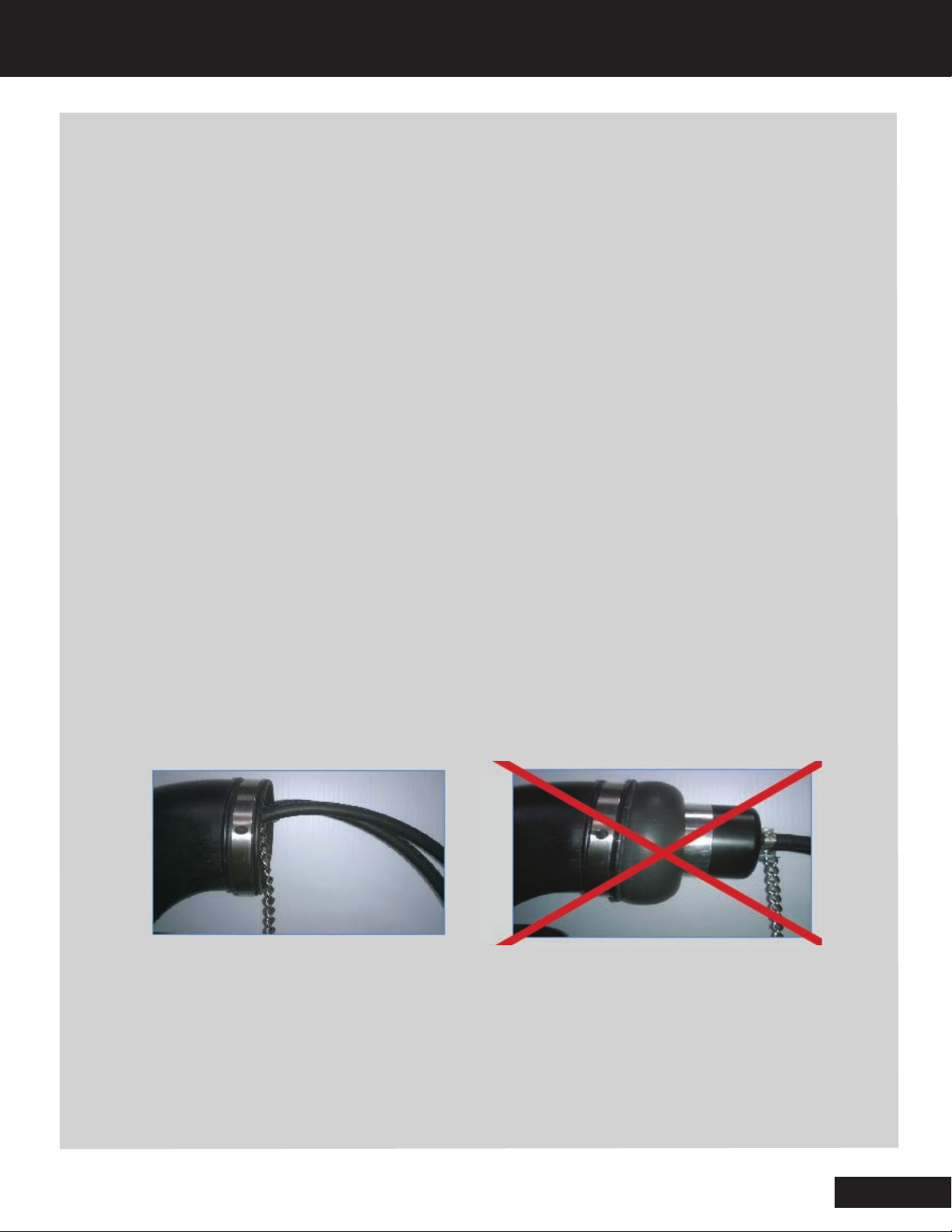
Proper Installation Improper Installation
Removal of Power INTAKE™Adaptor:
1. Remove vapor hose (or block off adaptor) at quick coupler to deflate tested system
2. ONLY AFTER system under test is fully depressurized, release internal pressure of Power INTAKE™
slowly by depressing Schrader valve
3. Detach safety chain / cable
4. Remove Power INTAKE™Adaptor from ductwork, making sure not to rub across sharp edges
EN

8
PROBLEM SOLUTION
No Green Light • Ensure electrical power cord is properly installed
• Check for blown fuse
Red Light Flashing • Open circuit / internal component
• Contact Redline Detection Technical Support
-see back of manual or machine for contact information
No Air Flow • Check connection to compressed air
• Open the flow control valve
• Check hoses are not kinked or pushed into machine
Poor Vapor Density or Volume • Insufficient Vapor Producing Fluid: Refill
• Flow Control Valve is partially closed
• Vapor Output Hose is kinked
High Test Pressure Reading • Vapor Output Hose is kinked
TROUBLESHOOTING / MAINTENANCE
EN

9
OPTIONAL ACCESSORIES
1. Temperature Sensor Port Adaptor [ 15-0056 ]
Use to access intake or exhaust system through temp sensor port
2. Pressure Sensor Port Adaptor [ 15-0055 ]
Use to access intake or exhaust system through pressure
sensor port
3. Oxygen Sensor Port Adaptor [ 15-0059 ]
Use to access exhaust system through oxygen sensor port
4. SmokeMeister™Wand [ 96-0088 ]
Tube delivers vapor to find wind and water leaks in cabin or trunk
5. Wand / Tip Adaptor [ 96-0094 ]
Install into SmokeMeister™wand to bench test components or
pinpoint vapor stream
6. Power Intake™Adaptor 2.9 in. (7.4 cm) Diameter [ 95-0081 ]
Inflatable block off bladder with a pressurized vapor pass-through
7. Bolt Kit [ 96-0850 ]
Hardware and instructions to easily fasten machine onto a tool cart
8. Magnet Kit [ 96-0080 ]
Hardware and instructions to easily attach heavy duty magnet to
hold machine onto metal cart
1
1
2
3
4
5
6
1
1
7
8
EN

FOR TECHNICAL SUPPORT: +1 714-451-1411 OR 1-877-557-6653 (US TOLL-FREE)
FOR NON-WARRANTY REPLACEMENT PARTS WITHIN THE US: WWW.MAZDAE-STORE.COM
FOR NON-WARRANTY REPLACEMENT PARTS OUTSIDE THE US: CONTACT YOUR LOCAL DISTRIBUTOR

MANUAL DE OPERACIÓN
DETECTOR DIAGNÓSTICO DE FUGA DE DOBLE PROPÓSITO
P/N MAZ-95-130-KT

CONTENIDOS
Especificaciones / Garantía................................................................................. 1
Funciones.............................................................................................................2-3
Accesorios.............................................................................................................. 4
Armado .................................................................................................................... 5
Seguridad................................................................................................................ 6
Instalación del adaptador ................................................................................... 7
Resolución de problemas / Mantenimiento ...................................................... 8
Accesorios opcionales ......................................................................................... 9

3
1
ESPECIFICACIONES
Dimensiones 14 in. x 9 in. x 15 in. (10 cm x 23 cm x 38 cm)
Peso – Solo de la máquina 27 lbs. (12.25 kg)
Peso – Solo del juego de accesorios 16 lbs. (7.25 kg)
Embalaje - Peso 46 lbs. (20.85 kg)
Embalaje - Dimensiones 20 in. x 15 in. x 25 in. (50 cm x 38 cm x 63 cm)
Suministro de energía 100-240V CA
Suministro de presión Aire comprimido
Presión de salida Modo TURBO 2 - 20 PSI (0.14 - 1.4 BAR)
Presión de salida Modo EVAP 11 - 14 en wc / 0.47 PSI / 0.032 BAR
Temperatura de funcionamiento 0°F a 140°F (-17°C a 60°C)
Humedad de funcionamiento Sin restricciones
Altitud de funcionamiento Sin restricciones
Manguera de salida de vapor 15 pies (5 m) TURBO 10 pies (3 m) EVAP
Modos de funcionamiento Ciclo de Vapor/ Ciclo de Aire Solo
Material de la carcasa Acero
Material de la cámara de vapor Aluminio en tochos
Conjunto de la cámara de vapor Atornillado
Garantía de la cámara de vapor De por vida
Garantía 3 años
El fabricante, Redline Detection, LLC (en adelante, "Redline") garantiza que este producto no tiene defectos de fabricación
y material bajo el uso y servicio normal durante un período de un año a partir de la fecha de compra. La responsabilidad de
Redline en virtud de esta garantía se limita a: (1) la reparación o reemplazo de cualquier parte o producto que se determine que
está defectuoso o, a criterio único de Redline (2) el reembolso del precio de compra. En cualquier caso, el producto se puede
devolver con envío prepago dentro del período de garantía de un año. Además, la cámara de vapor en cualquier producto de
Redline tiene garantía de por vida en cuanto a su integridad estructural: Cualquier cámara de vapor fabricada por Redline que
tenga una pérdida, grieta o se separe de alguna manera será reparada o reemplazada sin cargo por Redline. Los productos
solo deben ser utilizados por personas que tienen habilidades y conocimientos en el campo de reparación de vehículos a motor,
y el mantenimiento y uso indebido podría causar lesiones. En ningún caso Redline será responsable más allá del reemplazo del
producto o reembolso del precio de compra. Esta garantía quedará inválida si un producto no se mantiene adecuadamente, se
altera, abusa o se hace uso indebido de cualquier modo.
LA GARANTÍA ANTES MENCIONADA REEMPLAZA TODAS LAS DEMÁS GARANTÍAS, Y NO HAY OTRAS GARANTÍAS NI
DECLARACIONES DE NINGÚN TIPO HECHAS POR REDLINE, YA SEAN EXPLÍCITAS O IMPLÍCITAS, INCLUSO, ENTRE OTROS,
CUALQUIER GARANTÍA IMPLÍCITA DE COMERCIABILIDAD O IDONEIDAD PARA UN USO O APLICACIÓN EN PARTICULAR.
EL ÚNICO RECURSO PARA EL COMPRADOR POR CUALQUIER PRODUCTO DEFECTUOSO SERÁ SU REPARACIÓN, REEMPLAZO
O REEMBOLSO COMO SE MENCIONÓ ANTERIORMENTE, Y REDLINE NO SERÁ RESPONSABLE POR NINGÚN DAÑO ESPECIAL,
EMERGENTE, INCIDENTAL, INDIRECTO O PUNITIVO DEBIDO A PRODUCTOS DEFECTUOSOS, SIN IMPORTAR CÓMO HAYAN
SIDO CAUSADOS, BAJO NINGÚN PRINCIPIO DE RESPONSABILIDAD.
GARANTÍA
ES

4
2
TURBO/ALTA PRESIÓN
VISTA DELANTERA
1
3
54
6
2
10
911
12
7
8
1. Interruptor de palanca de selección modo/encendido
Interruptor de palanca a la izquierda para Turbo/Alta
presión, Interruptor de palanca a la derecha para baja
presión EVAP
2. Indicador de prueba de Turbo
Indica que se seleccionó prueba de Turbo / Alta presión
3. Manguera de salida de vapor Turbo / Alta presión
Administra vapor de alta presión en el sistema bajo
prueba
4. Medidor de flujo
Mide el caudal de flujo en el sistema bajo prueba
5. Manómetro del sistema
Muestra la contrapresión del sistema bajo prueba
6. Indicador de encendido
La luz verde indica que está correctamente conectado
a una fuente de electricidad
7. Válvula de control de flujo (variable)
Libera vapor/presión en el sistema.
Cierre la válvula de control de flujo para bloquear el
sistema para la prueba de disminución de presión
8. Manómetro de prueba
Indica la presión de prueba establecida por el
regulador
9. Interruptor de prueba de vapor
Inicia el ciclo de vapor de diez minutos. La luz roja
indica ciclo de vapor. Vuelva a pulsar para detener la
prueba
10. Interruptor de prueba de solo aire
Inicia el ciclo de solo aire de diez minutos. La luz azul
indica ciclo de solo aire. Vuelva a pulsar para detener
la prueba
11. Interruptor de reinicio
Borra la lógica almacenada
12. Regulador de presión ajustable
Ajusta la presión de prueba de 2 a 20 PSI
(0.14 a 1.4 BAR)
ES

5
3
VISTA DELANTERA
13 14 15 16
17
VISTA TRASERA
ES
18 18
19 20 21
13. Indicador de prueba de EVAP
Indica que se seleccionó prueba de EVAP / Baja
presión
14. Presión del sistema
Manómetro mixto del sistema EVAP
15. Medidor de flujo
Mide el caudal de flujo en el sistema bajo prueba
16. Manguera de salida de vapor EVAP / Baja presión
Administra vapor de baja presión en el sistema bajo
prueba
17. Válvula de control de flujo EVAP/Baja presión
(variable)
Libera vapor/presión en el sistema.
Cierre la válvula de control de flujo para bloquear el
sistema para la prueba de disminución de presión
*NOTA: Durante la prueba EVAP, la presión de salida
está fija y no se puede ajustar. El regulador ajustable se
utiliza únicamente durante la prueba de alta presión.
VISTA TRASERA
18. Puertos de llenado de líquidos (2x)
Retire el tapón de llenado de líquidos para llenar
la máquina con el agente de producción de vapor
aprobado por OE
19. Tomacorriente CA internacional (100-240V)
Entrada del cable de alimentación CA
20. Portafusibles
Fusibles 10A 250V más un fusible de repuesto
21. Entrada de aire comprimido
De ser necesario, retire el accesorio de acoplamiento.
Macho 1/4 pulgada
1/4” NPT (Rosca cónica para tubos)
EVAP/BAJA PRESIÓN
*
VISTA DELANTERA

4
ACCESORIOS INCLUIDOS
TURBO / ALTA PRESIÓN
1. Estuche para guardar accesorios [ 91-0006 ]
Se utiliza para almacenar los accesorios cuando no se usan
2. Conjunto de cono de escape [ 96-0004 ]
Para usar para cerrar aperturas de 1 in. (2.5 cm) a 3.4 in. (8.6 cm) para
introducir vapor en los sistemas de escape e inducción (EVAP)
3. Conjunto de kit de tapón de bujía [ 96-0007 ]
Cierra las aperturas para la prueba del sistema de baja presión
4. Luz halógena de inspección [96-0011]
12V CC con cable de 20 pies (6.1 m). Siempre utilice para localizar fugas
5. Cable de alimentación CA [ 20-0010 ] para tomacorriente estándar de
EE. UU.
6. Dos frascos de líquido de producción de humo aprobado por OE [ 96-
0039 ] 8 onzas fluidas (237 ml)
El líquido de producción de vapor realizará más de 100 pruebas típicas
por frasco
Importante: NO contiene tinte / contaminantes
7. Llave hexagonal [ 80-0009 ]
Para retirar / reemplazar el tapón de llenado de líquidos
8. Dos adaptadores Power INTAKE™, 1.5 pulgadas (4.8 cm) 2x [ 95-0080 ]
Cámara de aire inflable de bloqueo con pasaje de vapor
9. Adaptador Power INTAKE™1.9 pulgadas (7.4 cm) [ 95-0086 ]
Cámara de aire inflable de bloqueo con pasaje de vapor
10. Dos conectores de bloqueo [ 96-0084 ]
Se utilizan junto con los adaptadores Power INTAKE™cuando se ingresa
vapor desde una ubicación alternativa.
11. Easy INTAKE ™ [ 95-0082 / B]
El premiado Easy INTAKE™es una cámara de aire inflable de bloqueo
con pasaje de vapor presurizado que permite a los técnicos evaluar
todo el sistema de entrada o escape de manera rápida y fácil.
12. Adaptador del sistema de refrigeración [ 96-0086 ]
Use este adaptador para evaluar un sistema de refrigeración vacío
después de una reparación del motor para verificar fugas del sistema de
refrigeración.
13. Adaptador de manguera EVAP de seis tapones de gas* [ 96-0128 ]
Los adaptadores de manguera EVAP convertirán los adaptadores de
tanque de gas existentes de su herramienta previamente requerida para
usar en esta herramienta.
14. Conector del cuello de depósito universal [ 95-0011 ]
Este sistema de conector del cuello de depósito de combustible univer-
sal se ajusta al 100% de los vehículos para simplificar las pruebas de
EVAP.
15. Tapón de gas de rosca única [ 96-0092 ]
Para usar para bloquear la cámara de aire si realiza la prueba desde la
entrada y luego bloquea el escape para simular la presión de refuerzo.
16. Kit de herramientas de servicio EVAP [ 96-0003 ]
Herramienta de extracción la válvula Schrader
Adaptador para el puerto de servicio Evap
12
14
16
15
4
3
5
67
8
12
11
13
1
910
ES

5
ARMADO
1. LLENE/AGREGUE LÍQUIDO DE PRODUCCIÓN DE VAPOR
a. Retire el tapón de llenado de líquidos con la llave hexagonal.
b. Vierta el líquido de producción de vapor aprobado de Redline en el puerto
de llenado de líquidos
c. Llene con el líquido hasta la parte superior del puerto
d. Vuelva a colocar el tapón de llenado de líquidos
2 onzas fluidas (60 ml) como máximo. Use solo líquido de producción de
vapor aprobado de Redline
Nunca use tintes, solventes u otros contaminantes en los sistemas
de entrada o escapa porque podrían recubrir o dañar sensores,
catalizadores o filtros críticos
2. CONECTAR A UNA FUENTE DE ELECTRICIDAD
• Conecte un cable de alimentación de la capacidad apropiada al
tomacorriente de CA
• La luz verde indicadora de energía se ilumina cuando hay una conexión
adecuada a fuente de energía
*INTERRUPTOR DE PALANCA DE SELECCIÓN MODO/ENCENDIDO:
Interruptor de palanca a la izquierda para Turbo/Alta presión,
Interruptor de palanca a la derecha para baja presión EVAP
INDICADOR DE ENERGÍA:
LUZ VERDE: La máquina cuenta con electricidad adecuada
SIN LUZ: No hay electricidad
Nunca conecte el detector diagnóstico de fuga de doble propósito
al vehículo con el motor encendido
!
!
!
3. CONECTAR A UN SUMINISTRO DE AIRE
a. Conecte un suministro de aire comprimido a la Entrada de Aire
*De ser necesario, reemplace el accesorio de acoplamiento rápido. Macho
NPT de 1/4 de pulgada macho.
4. PARA AJUSTAR PARA LAS PRUEBAS EVAP / BAJA PRESIÓN
Pulse prueba de vapor o de solo aire para comenzar el ciclo de 10 minutos.
Vuelva a pulsar para detener.
a. La LUZ ROJA indica la prueba de vapor
La LUZ AZUL indica la prueba de solo aire
b. El medidor de flujo indica flujo y mide el tamaño de la fuga
5. PARA AJUSTAR PARA LAS PRUEBAS TURBO / ALTA PRESIÓN
a. Cierre la válvula de control de flujo
b. Jale de la perilla del regulador de presión para destrabar
c. Pulse prueba de vapor o de solo aire para comenzar el ciclo de 10 minutos.
Vuelva a pulsar para detener.
La LUZ ROJA indica la prueba de vapor
La LUZ AZUL indica la prueba de solo aire
d. Gire la perilla del regulador de presión hasta la presión de prueba deseada.
Para ajustar, gire en sentido de las agujas del reloj para aumentar y en
sentido contrario para disminuir
*
e. Presione la perilla del regulador de presión para trabar.
6. ABRIR LA VÁLVULA DE CONTROL DE FLUJO PARA LIBERAR EL VAPOR/PRESIÓN
7. USAR LA LUZ DE INSPECCIÓN PARA IDENTIFICAR LA PÉRDIDA
8. REPARAR
9. VOLVER A REALIZAR LA PRUEBA PARA CONFIRMAR LA REPARACIÓN
ES

86
EVAP/BAJA PRESIÓN SEGURIDAD
SIGA ÚNICAMENTE LOS PROCEDIMIENTOS DE PRUEBA DE FUGA APROBADOS POR MAZDA
Los procedimientos en esta sección tienen la intención de ser pautas básicas para que los usuarios
practiquen usar el detector diagnóstico de fuga de doble propósito (modo EVAP/Baja presión).
Este manual de operación no debe usarse en reemplazo del sentido común:
• Use este equipo de la forma especificada por el fabricante
• Entienda los procedimientos de operación
• Siga todas las precauciones de seguridad
PRECAUCIONES DE SEGURIDAD
• Todo el trabajo de diagnóstico debe hacerse con el motor apagado
• No deje un vehículo sin supervisión mientras el equipo está conectado o en funcionamiento
• El equipo opera con voltaje CA
• No realice pruebas cerca de una fuente de chispa de encendido
• Cuando trabaja con el sistema de combustible, debe trabajar en un área bien ventilada
• Siempre use el equipo de protección de seguridad adecuado. Use protección para ojos y guantes de
protección estándar de la OSHA cuando usa este equipo
SIGA ÚNICAMENTE LOS PROCEDIMIENTOS DE PRUEBA DE FUGA APROBADOS POR MAZDA
Los procedimientos en esta sección tienen la intención de ser pautas básicas para que los usuarios
practiquen usar el detector diagnóstico de fuga de doble propósito (modo TURBO/Alta presión).
El detector de fuga de doble propósito de Mazda está diseñado para ser utilizado junto con los
adaptadores Power INTAKE™o los adaptadores de entrada de diámetro fijo suministrados solo para
evaluar los sistemas de entrada y escape de motores turbo de inyección de combustible.
NO USE TURBO / ALTA PRESIÓN EN EL SISTEMA EVAP
PRECAUCIONES DE SEGURIDAD
• Todo el trabajo de diagnóstico debe hacerse con el motor apagado
• Para uso exclusivo de técnicos profesionales
• Asegúrese de que el vehículo esté asegurado y estable
• Tenga cuidado al conectar y desconectar el suministro de aire comprimido del taller
• No deje un vehículo sin supervisión mientras el equipo está en funcionamiento
• Siempre utilice equipo de protección personal
• Esta guía de instalación no tiene la intención de reemplazar el sentido común y buen juicio
TURBO/ALTA PRESIÓN SEGURIDAD
!
!
!
ES
Table of contents
Languages:
Popular Security Sensor manuals by other brands

STEINEL
STEINEL HF 360-2 IP manual

Honeywell
Honeywell PEHA MLS Digital Hi-Bay D MLS2001AHBF Installation and commissioning instructions

STEINEL
STEINEL HF 180 manual

Elkron
Elkron IR600FC/N Installation, programming and functions manual

Tyco
Tyco WS4933 Series Installation and operating instructions

THORLABS
THORLABS PDAPC1 user guide