manuals.online logo
Brands
  1. Home
  2. •
  3. Brands
  4. •
  5. Lince
  6. •
  7. Security Sensor
  8. •
  9. Lince DTP 100 User manual

Lince DTP 100 User manual

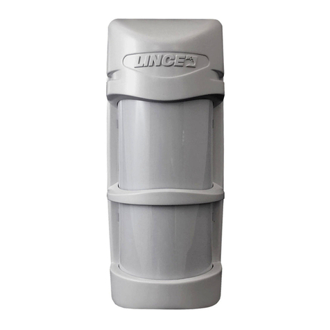
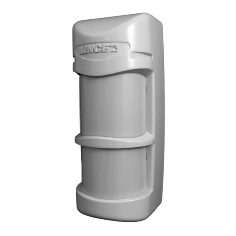
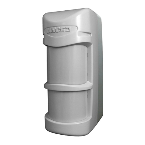
Rivelatore di presenza doppia tecnologia
MADE IN ITALY ART. 1497-1578
Conforme alle normative Cei 79/2 2° ediz.
230603241106 rev 3
DESCRIZIONE Il DTP100 riunisce in un unico dispositivo un sensibile rilevatore a microonda
ed un affidabile sensore ad infrarosso, entrambi gestiti da un potente microprocessore.
Appositamente studiato e realizzato per il funzionamento in ambienti molto difficili , garantisce
un eccellente grado di immunità a fenomeni che in altri tipi di sensori possono causare falsi
allarmi.
La sequenza dei preallarmi forniti dai due sensori in esso contenuti viene opportunamente
analizzata dal microprocessore evitando così che fenomeni esterni come correnti d'aria,
sorgenti di calore, e disturbi di origine elettrica diano luogo ad indesiderati allarmi. La
realizzazione con componenti SMD ha reso possibile ottenere dimensioni ridotte nonostante la
complessità delle funzioni svolte, una maggiore affidabilità del circuito e non ultima una elevata
immunità a disturbi elettromagnetici. Facilmente adattabile a qualsiasi tipo di installazione sia a
parete che ad angolo è dotato di indicatori luminosi per la verifica del corretto orientamento e
regolazioni di sensibilità dei sensori. La programmazione delle funzioni del sensore si effettua
tramite dip-switch.
DESCRIPTION This model combines in only one device a sensitive microwave detector with a
reliable infrared sensor, both managed by a powerful microprocessor. On purpose studied and
realized to guarantee perfect functioning in difficult places, it also guarantees high immunity
against phenomena which in other different devices may cause false alarms.
The sequence of the pre-alarms provided by the two built-in sensors, is duly analysed by the
microprocessor, thus avoiding that external phenomena such as air currents, heat sources, little
animal movements or electric origin troubles, may cause undesired false alarms.
SMT technology has allowed reduced dimensions, although functionality complexity, a high
reliability and high electromagnetic immunity. Suitable both on wall and corner installations, it is
supplied with luminous indicators to check correct orientation and adjustment of sensor
sensitivity. Programmation of the sensor’s functions is made by the dip switch.
INSTALLAZIONE Il DTP 100 offre prestazioni ottimali ed una elevata immunità contro i falsi
allarmi. Anche se più tollerante di altri sensori tradizionali, è consigliabile praticare una buona
installazione attenendosi alle istruzioni. Individuare il punto dove fissare il sensore valutando i
passaggi più probabili e gli oggetti più facilmente asportabili da un eventuale intruso.
L'altezza consigliata è di 2,2 m. Per il fissaggio agire come segue: Togliere la copertura facendo
pressione sugli incastri ( C). Fissare il supporto di fissaggio ( B) con le viti ed il tassello in
dotazione ad un'altezza da terra compresa tra i 2,10 m e i 2,30 m. Fissare il sensore al supporto
e prima di serrare le viti ( A) orientare il sensore secondo le esigenze.
Effettuare i collegamenti, chiudere il sensore facendo attenzione che gli scatti automatici siano
incastrati. Se necessario è possibile eliminare lo snodo di fissaggio ( B) e fissare direttamente il
sensore a parete, o ad angolo usando le preforature previste.
COLLEGAMENTI I collegamenti con il sensore DTP 100 devono essere effettuati con cavo
schermato: collegare lo schermo alla massa della centrale, lasciandolo scollegato su lato
sensore. Se la distanza tra il sensore e la centrale è notevole, assicurarsi che non vi sia caduta
di tensione. Per la descrizione dei morsetti fare riferimento alla seguente tabella:
INSTALLATION The DTP100 offers excellent performances and high immunity against false
alarms. Even if more tolerant than other traditional sensors, it is recommended to effect a good
installation, following the present instructions.
Find an out-of-reach place where to fix the sensor, considering the movements of possible
intruders and the most easily removable objects. Recommended height is 2.2 m. For the fixing
do as follows: Take the cover off by pressing on the joints (C) Fix the fixing support (B) with the
screw and the supplied dowel at a height between 2,10 and 2,30 m. Fix the sensor to the
support and before tightening the screw (A), direct the sensor. Make the connections and close
the sensor paying attention that the automatic clicks are well stuck. If necessary it is possible to
eliminate the fixing articulation (B) and directly fix the sensor to the wall, or at corner by using
the previewed pre perforations.
CONNECTIONS Connections with the DTP100 sensor shall be done with shielded cable:
connect the shield to the control panel ground, keeping it disconnected on the sensor side. If
distance between the sensor and the control panel is considerable, make sure no power loss
may happen. For terminal description , refer to
the following schedule:
WT
Morsetto per l'esclusione a distanza dei led di allarme, e abilitazione memoria
(vedi paragrafo Esclusione led ed abilitazione memoria).
Terminal for remote exclusion of the alarm leds and memory enabling (see para.
“Leds exclusion and memory enabling)
AS Contatti dello switch antisabotaggio (8) Normalmente chiuso: Collegare questi
morsetti alla linea antisabotaggio
Tamper switch contacts (8) NC: Connect these terminals to the tamper line
NC Contatti del relé di allarme Normalmente Chiuso: Collegare ad una linea di
allarme
NC alarm relay contact: connect to an alarm line
AC Contatto relè N.C. dell’antimascheramento. Si apre quando il sensore attiva
l’allarme Antimask e Warning.
NC relay contact: Antimask. It opens when the sensor activates the Antimask
and Warning alarm.
+ / - Morsetti di alimentazione 12V , 34mA, quando il sensore viene alimentato
impiega circa 60 sec. Per stabilizzarsi.
Power terminal: 12V 34mA. Once the sensor is powered it takes 60 sec. to
become stable.
Technical features
Infrared sensor Low noise double element
Microwave frequency 10,525 Ghz strip line
Circuit realization SMT with microprocessor
Range 15 / 23 mt
Power From 8 to 16 Volt dc
Absorption 34 mAh
Alarm relay N.C. silent 10 Ωseries
Installation Wall
Antitamper switch N.C. Contact
AND/OR function Yes
ANTIMASK function Yes
WARNING function end MEMORY Yes
Operating temperature -10° +50° C
Dimensions (mm LxHxB) 71x102x56 without articulation
Weight 106g
Caratteristiche tecniche
Sensore infrarosso Doppio elemento a basso rumore
Frequenza microonda 10,525 Ghz strip line
Realizzazione del circuito SMT con microprocessore
Portata 18 / 23 m
Alimentazione da 8 a 16 Volt cc
Assorbimento 34 mAh
Relè di allarme N.C. silenzioso 10 Ωin serie
Installazione Parete
Switch antisabotaggio N.C. contatto dedicato
Funzione AND/OR SI
Funzione ANTIMASK SI
Funzione WARNING e MEMORIA SI
Temperatura di funzionamento -10° +50°C
Dimensioni (mm LxHxP) 71x102x56 senza snodo
Peso 106g
C
B
A
ESCLUSIONE LED ED ABILITAZIONE MEMORIA Il morsetto WT consente di escludere a
distanza i led di allarme e conseguentemente abilitare la memoria del sensore . Per attivare
questa funzione si deve inviare un positivo sul morsetto WT (+OFF sulle centrali Lince). In caso
di allarme, il sensore che lo ha generato rimarrà con il led rosso acceso fisso fino all’inserimento
successivo.
N.B. Inserendo l’impianto con il sensore in allarme anche se temporizzato, si attiverà la
memoria.
ALARM EXCLUSION The WT terminal allows to remotely exclude the alarm leds and
consequently enable the sensor’s memory. To activate this function , send a positive on the
WT terminal (+OFF on Lince’s control panels). In case of alarm, the sensor which has been
generating it, will stay with fix red on, until the following activation. Att.: Even when timed
sensor, while activating the system, the memory will be activated , too.
FUNZIONE AND/OR In AND si ha l’allarme solo quando tutti e due i sensori rilevano la causa,
mentre in OR quando soltanto uno dei due si attiva.
AND/OR FUNCTION AND causes the alarm when both sensors are detecting, OR when
only one sensor is activated.
FUNZIONE ANTIMASK Ad impianto inserito, il sensore è operativo anche in caso di
accecamento del sensore infrarosso dopo 5 rilevazioni (entro 30 secondi ) della microonda.
ANTIMASK FUNCTION When the system is on, in case the infrared sensor has been
covered, the alarm will be switched on after 5 pre-alarms of the microwave.
FUNZIONE WARNING Quando il sensore è inibito, (+ Off sul morsetto WT), in caso di
guasto o accecamento di una delle due tecnologie, il microprocessore, dopo 50 rilevazioni di un
sensore senza che l'altro rilevi alcun allarme, esclude automaticamente il sensore che non
risponde. L'anomalia verrà segnalata con l’apertura dello scambio AC ed il lampeggio del led
corrispondente alla tecnologia guasta, il ripristino avverrà alla prima rilevazione utile della
tecnologia accecata.
ATT. Se si toglie il + off da WT il sensore ripristina la visualizzazione dei led dopo
circa 15/20 secondi
WARNING FUNCTION When the sensor is inhibited (+OFF on the WT terminal) in case of
breakdown or covering of one of the two technologies, the microprocessor automatically
excludes the sensor which does not answer, thus signalling the anomaly by the flashing
up of the corresponding led, after 50 detections of one sensor, when the other detects no
alarm. The AC exchange will be opened thus signalling the anomaly and the led of the
correspondent to the faulty technology will flash up.
ATT.: If +OFF is taken away form the WT, the sensor restores the led visualisation
after about 15/20 seconds.
PROGRAMMAZIONE DELLE FUNZIONI Tramite i dip-switch è possibile programmare il
sensore in vari modi di funzionamento (a riguardo vedi tabella sottostante):
DIPSWITCH ON OFF
N°.1 LED ACCESI SPENTI
N°.2 AND/OR OR AND
N°.3 ANTIMASK ATTIVA DISATTIVA
N°.4 WARNING ATTIVA DISATTIVA
PROGRAMMATION The sensor can be programmed in different modes, by the
dipswitch (see below schedule):
DIPSWITCH ON OFF
N°.1 LED ON OFF
N°.2 AND/OR OR AND
N°.3 ANTIMASK ON OFF
N°.4 WARNING ON OFF
FUNZIONE DEI LED Led giallo: Lampeggiante, la microonda sta rilevando del movimento
nell'ambiente
Led verde: Acceso fisso, il sensore infrarosso ha rilevato una presenza
Led rosso: Acceso fisso, condizione di allarme.
LEDS Yellow: Flashing, it indicates that the microwave is detecting a movement
Green: On fix,it indicates that the infrared sensor has been detecting
Red: On fix: alarm condition
COPERTURA: La copertura dell'area protetta è determinata dall'effetto combinato dei due
sensori presenti all'interno del DTP 100. La microonda ha un angolo di copertura di 90° sul
piano orizzontale mentre il sensore infrarosso, all'interno della stessa area, dispone di 20 fasci
su 4 livelli, ognuno dei quali genera un segnale differenziale.
In ultima pagina sono rappresentati i grafici di copertura di entrambe i sensori.
COVERING The protected area is determined by the combined effect of the two sensors inside
the DTP 100.
The microwave has a 90° angle covering on horizontal plane, while the infrared sensor has 20
beams on 4 levels, each of them generating a differential sensor. In the last page, we show the
covering graphs of both the infrared beams and microwave.
PROVA DI COPERTURA: Eseguire nell'ambiente in cui è installato il DTP100 una prova di
portata aumentando gradualmente la sensibilità della microonda tramite il trimmer (range) al
fine di ottenere l’accensione del led giallo fino al limite della zona da proteggere e non oltre.
N.B.: La prova di copertura deve essere effettuata con il sensore perfettamente chiuso.
DETECTING TEST: Where the detector is installed, check the covering by gradually
increasing the sensitivity (trimmer) so that the microwave detects any movement , thus showed
on the yellow led.
N.B.: Covering test shall be effected with a perfectly closed senso
TEST:
Alla prima alimentazione il sensore si predispone in test mode, e vi rimane per circa 1 minuto. TEST:
In questo frangente il sensore verifica che entrambe le tecnologie siano efficienti.
Se il test non si conclude positivamente, si avrà il lampeggio della tecnologia difettosa.
Si avranno i tre led che si accenderanno ciclicamente per circa 1 minuto.
Attendere sempre almeno 2 minuti prima di effettuare le prove di copertura.
Se il sensore non avrà segnalato anomalie tramite il lampeggio di uno dei suoi led,
sarà attivo al 100 %.
Grafico di copertura DTP 100 Grafico di copertura DTP 100/23
Activation the sensor switches on test mode, and stays for about 1 minute
At this moment the sensor cheks if both technologies are efficient
If the test does not give good result, the fautly technology will flashes up.
The three leds will cyclically light up for 1 minute
Always wait 2 minutes at least before making the covering tests.
If the sensor does not flash up thus signalling any anomaly, it is 100% active.
Led di segn. Rosso =
Allarme
Verde =
Infrarosso
Giallo =
Dip switch
delle
impostazio
ni
Sensore
piroelettrico .
(
Non toccare con
Trimmer
portata
microonda
Microswitch
antisabotag

This manual suits for next models

1

Other Lince Security Sensor manuals

Lince ZENITH GOLD 869 Series User manual

Lince

Lince ZENITH GOLD 869 Series User manual

Lince ZENITH GOLD 869 Series User manual

Lince

Lince ZENITH GOLD 869 Series User manual

Lince BOBBY GOLD Series User manual

Lince

Lince BOBBY GOLD Series User manual

Lince Bobby Universale User manual

Lince

Lince Bobby Universale User manual

Lince 1534JOLLY User manual

Lince

Lince 1534JOLLY User manual

Lince ZENITH IR User manual

Lince

Lince ZENITH IR User manual

Lince GR868 Bobby User manual

Lince

Lince GR868 Bobby User manual

Lince GR868 Bobby User manual

Lince

Lince GR868 Bobby User manual

Lince OBLO'/E User manual

Lince

Lince OBLO'/E User manual

Lince 4059GR868ZENITH User manual

Lince

Lince 4059GR868ZENITH User manual

Lince ZENITH GOLD 869 Series User manual

Lince

Lince ZENITH GOLD 869 Series User manual

Lince 9504-GOLD-DT User manual

Lince

Lince 9504-GOLD-DT User manual

Lince BABY BA User manual

Lince

Lince BABY BA User manual

Lince Sigma 1946-BOBBY180-24-AM-V User manual

Lince

Lince Sigma 1946-BOBBY180-24-AM-V User manual

Lince 9528-GOLD-TP-L User manual

Lince

Lince 9528-GOLD-TP-L User manual

Lince 1906-BOBBY-T-E User manual

Lince

Lince 1906-BOBBY-T-E User manual

Lince 1896BOBBY-AM/U User manual

Lince

Lince 1896BOBBY-AM/U User manual

Lince DTP 20 User manual

Lince

Lince DTP 20 User manual

Lince 1597ZENITHDT User manual

Lince

Lince 1597ZENITHDT User manual

Lince BABY User manual

Lince

Lince BABY User manual

Lince JOLLY User manual

Lince

Lince JOLLY User manual

Lince BOBBY-AM User manual

Lince

Lince BOBBY-AM User manual

Lince Bobby User manual

Lince

Lince Bobby User manual

Lince GR868DT User manual

Lince

Lince GR868DT User manual

Popular Security Sensor manuals by other brands

Abra AK-330 quick start guide

Abra

Abra AK-330 quick start guide

Ametek LAND MILLWATCH user guide

Ametek

Ametek LAND MILLWATCH user guide

Duevi DDT-2 Installation and use manual

Duevi

Duevi DDT-2 Installation and use manual

brennenstuhl MD user manual

brennenstuhl

brennenstuhl MD user manual

GJD D-TECT 1 HT manual

GJD

GJD D-TECT 1 HT manual

Profort vibraSpot manual

Profort

Profort vibraSpot manual

SII Vortex-EM manual

SII

SII Vortex-EM manual

Visonic DA-5 installation instructions

Visonic

Visonic DA-5 installation instructions

Det-Tronics X5200 Addendum

Det-Tronics

Det-Tronics X5200 Addendum

U-Line H-9467 manual

U-Line

U-Line H-9467 manual

Ziton ZR432-2P Installation sheet

Ziton

Ziton ZR432-2P Installation sheet

Omron F3SG-4RA****-25-01TS Series Quick installation manual

Omron

Omron F3SG-4RA****-25-01TS Series Quick installation manual

EVERSPRING SP814 manual

EVERSPRING

EVERSPRING SP814 manual

hager Comfort EE87 Series quick start guide

hager

hager Comfort EE87 Series quick start guide

Siemens IS404 instruction manual

Siemens

Siemens IS404 instruction manual

Ansell AE3LED/3M installation instructions

Ansell

Ansell AE3LED/3M installation instructions

Baumer URCK 09G8914 quick start guide

Baumer

Baumer URCK 09G8914 quick start guide

Niko 7804 Series manual

Niko

Niko 7804 Series manual

manuals.online logo
manuals.online logoBrands
  • About & Mission
  • Contact us
  • Privacy Policy
  • Terms and Conditions

Copyright 2025 Manuals.Online. All Rights Reserved.