manuals.online logo
Brands
  1. Home
  2. •
  3. Brands
  4. •
  5. Mazurczak
  6. •
  7. Measuring Instrument
  8. •
  9. Mazurczak NT Series Owner's manual

Mazurczak NT Series Owner's manual

Installation and Operating Instructions for WG 36/09.12/
Rod-Type Level Probe NT Original operating manual E-MBA 322b
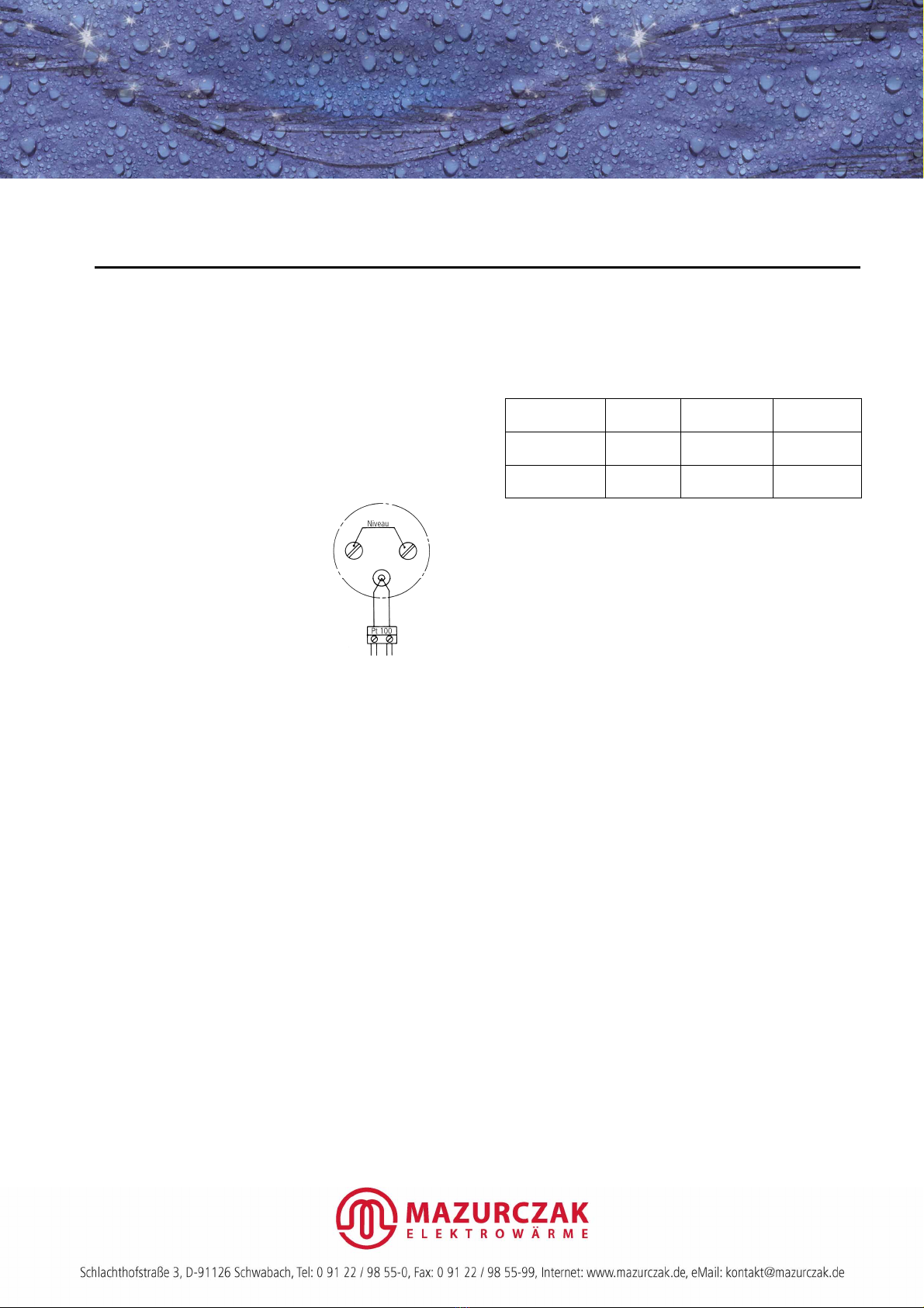
The rod-type level probe NT measures the temperature of the liquid
with a Pt 100 temperature sensor (DIN EN 60751) and the level of
the liquid by means of conductive level measurements.
The level probes NT are only designed for commercial and
industrial use.
Do not use them in inflammable or explosive fluids.
In order to ensure correct and reliable operation, the following must
be observed:
1. Electrical Safety
Connection diagram
The probe may be connected only
by a suitably trained electrician!
The probes may be used only together
with a suitable electronic controller.
Maximum probe voltage: 20 V ~ (AC).
In the case of inductively or capacitively
coupled interference on the control
cable, we recommend that you use
screened cables. The screen may be
connected to ground only at one end of
the cable.
Types NT…/BC-…
The terminal casing BC is opened and closed with the mounting
wrench SB. For terminal casing BC, ensure that the pull relief, the
pressure screw for the cable gland and the cover screws are correctly
tightened upon assembly. Tighten the terminal casing cover until the
cover makes a positive connection with the cable gland. This ensures
optimum sealing of the casing.
Types NT…/LC-…
The mounting wrench SL (accessory) is used for opening and closing
the terminal casing LC. Take care that the pull-relief, the pressure
screw and the cover are tightened securely. Tighten the terminal
casing cover until the cover makes a positive connection with the
cable gland. This ensures optimum sealing of the casing.
If you install your own cables, you must remove the white plastic
insert below the pull-relief clamp when installing cables with a
diameter of >8 mm (maximum cable diameter: 9.5 mm).
The sealing insert for the cable gland must be selected from the
following table. If replacement inserts are needed, they can be
ordered as accessories.
Cable entry Cable-
[mm]
Sealing insert
Colour
Article number
(accessory)
Terminal casing
BC
4 – 6,5
6,5 – 9,5
yellow
black
1702200001
1702500001
Terminal casing
LC
4 – 6,5
6,5 – 9,5
yellow
black
4921000053
4921000050
2. Operating Conditions
The materials of the rod-type level probe and the temperature sensor
must be chemically resistant to the liquid to be monitored and must
be able to withstand the temperature of the liquid.
The ambient temperature at the terminal housing may not exceed
50 °C. Neither the terminal housing nor the cable may be immersed
in the liquid.
The probe may be used with reservations in liquids with a tendency
to form crystals or encrustation..
Rod-type level probes made of metal may, if necessary, be cut to the
required length by the user.
Universal rod-type probes made of PTFE may not be shortened.
Operating temperatures
•For metallic probe rods with PO sheath (black): 70 °C
•For metallic probe rods with PTFE sheath (translucent): 90 °C
•For probe rods sheathed with PTFE (white): 100 °C
3. Installation Conditions
When installing the probe, ensure that the rods do not touch each
other. The probe is installed in vertical position.
The rod level-probe can also be mounted on the edge of a tank with
the aid of the special support HB (Article No 1700020001) or HL
(Article No. 4921000071) or with a cross-beam. Both the rod
terminal casing and the support have holes through which a cabel tie
can be inserted in order to prevent inadvertent removal of the rod
level-probe from the support. The following sleeves (accessories) are
also available for mounting the level-probe.
Support Sleeve
(accessory)
Article number
(accessory)
Terminal casing
BC HB Support sleeve HM
Mounting sleeve EM
1700010001
1700011001
Terminal casing
LC HL Mounting sleeve ML 4921000074
4. Principle of Operation
The Pt 100 temperature sensor measures the temperature of the
liquid and this value is processed by the temperature limiter ETB 1.
The level probe receives a low AC voltage from the temperature
limiter ETB 1. The circuit is completed by the electrically conductive
liquid between the rods of the probe.
5. Commissioning and Maintenance
The signalling unit is a safety device and must therefore be tested for
correct operation after installation and at suitable intervals
thereafter. This test must also include testing that the desired effect
(e.g. protection against excessive temperatures) is achieved.
Remove any encrustation which is deposited on the rods.
Particularly in the case of conductive liquids, there is a risk of
incorrect operation due to the formation of a conductive path
between the probe rods.
In order to avoid this, the sensitivity of the temperature limiter ETB 1
can be adjusted to match the conductivity of the liquid.
Non-compliance with these instructions, disassembly of the
switch or other manipulations will invalidate the warranty.
If you wish to make a claim under the warranty or required repairs,
return the cleaned and neutralized level probe to the
manufacturer postage paid with details of the defect.
These installation instructions form an integral part of the device and
must be kept available throughout the service life of the device.
The distribution or reproduction of this document and the reuse or
disclosure of its content are forbidden unless expressly permitted.
Infringements of this will incur penalties.
All patent, utility patent or design patent registration tights reserved.

Popular Measuring Instrument manuals by other brands

YSI SonTek ADVField Technical documentation

YSI

YSI SonTek ADVField Technical documentation

Gossen MetraWatt METRACLIP 85 Start guide

Gossen MetraWatt

Gossen MetraWatt METRACLIP 85 Start guide

Kimo MP 202 Directions for use

Kimo

Kimo MP 202 Directions for use

Extech Instruments MA260 user guide

Extech Instruments

Extech Instruments MA260 user guide

Flow vision FC50-EX Instructions for installation and adjustment

Flow vision

Flow vision FC50-EX Instructions for installation and adjustment

LINSHANG LS193 user manual

LINSHANG

LINSHANG LS193 user manual

Larson Davis Spartan 730 quick start

Larson Davis

Larson Davis Spartan 730 quick start

Camlab Water CW2050 manual

Camlab

Camlab Water CW2050 manual

Leica Geosystems Builder Series How-to guide

Leica Geosystems

Leica Geosystems Builder Series How-to guide

Seca 274 manual

Seca

Seca 274 manual

Pacific Scientific 5170 instruction manual

Pacific Scientific

Pacific Scientific 5170 instruction manual

Chauvin Arnoux C.A 1510 manual

Chauvin Arnoux

Chauvin Arnoux C.A 1510 manual

OHAUS ST300 instruction manual

OHAUS

OHAUS ST300 instruction manual

Keysight Technologies MXA N9020A-508 Configuration guide

Keysight Technologies

Keysight Technologies MXA N9020A-508 Configuration guide

SIXTOL SX3005 Instructions for use

SIXTOL

SIXTOL SX3005 Instructions for use

Raymarine LifeTag System Installation & commissioning guide

Raymarine

Raymarine LifeTag System Installation & commissioning guide

Mirion Technologies LDM 320 user manual

Mirion Technologies

Mirion Technologies LDM 320 user manual

FLIR MR55 user manual

FLIR

FLIR MR55 user manual

manuals.online logo
manuals.online logoBrands
  • About & Mission
  • Contact us
  • Privacy Policy
  • Terms and Conditions

Copyright 2025 Manuals.Online. All Rights Reserved.