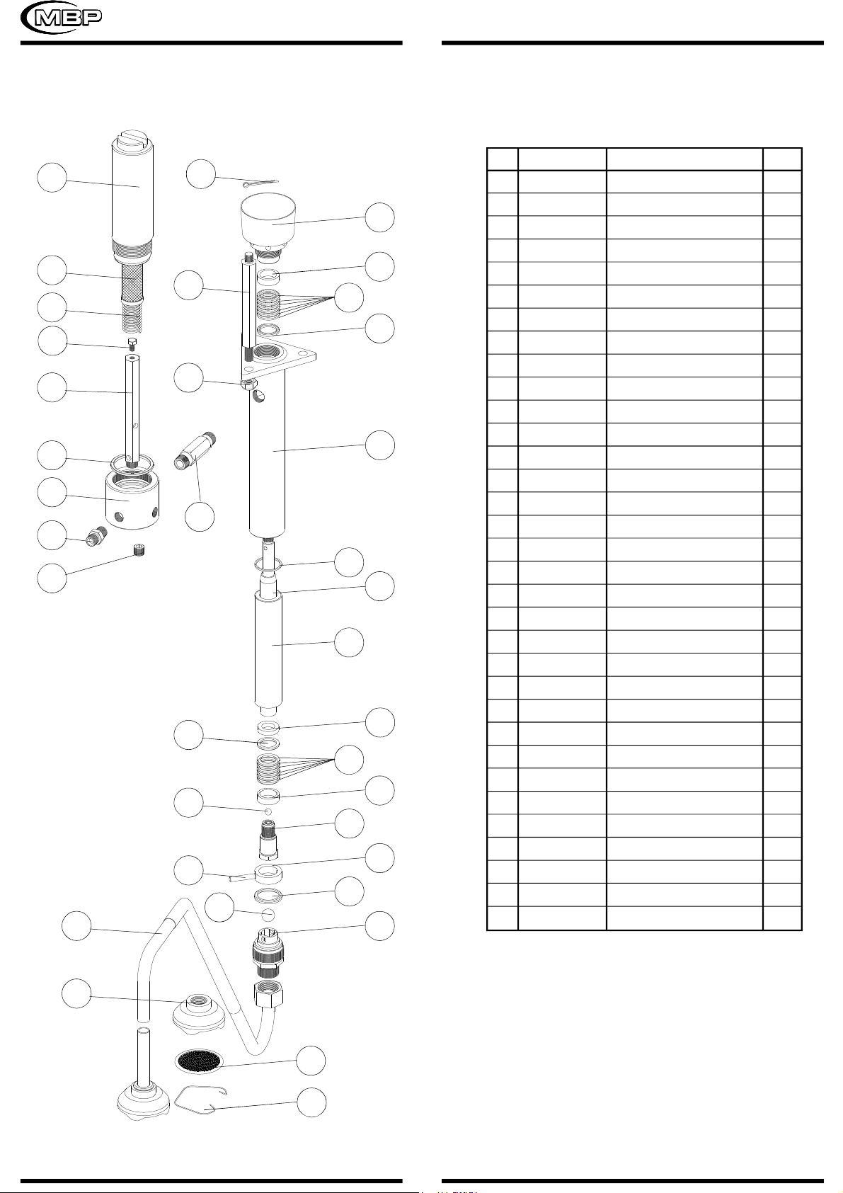
mbp BUD 15BS User manual

This instruction manual contains IMPORTANT
WARNINGSAND INSTRUCTION THAT MUST BE READ
BEFORE OPERATING THE PUMP
INSTRUCTIONS AND PARTS LIST
SPRAY EQUIPMENT
MBPS.L. C/.Anboto, 17 Poligono ANSOLETA Phone: (34) 945-132744 Fax.
(34) 945-134756
01006 VITORIA(Alava) / SPAIN
HYDRAULIC
RATIO 15:1
MODELS BUD 15BS BUD 15CS

WARNING
ATTENTION!! Read and understand all instructions carefully
before operating equipment.
INJECTION HAZARD
This equipment generates very high fluid pressure. Spray
from the gun, leaks or ruptured components can inject fluid
through your skin and into your body and cause extremely
serious bodily injury.
The spray gun should never be handled carelessly, nor
spray directed toward any part of the body. Keeps your hands
and fingers away from spray gun nozzle.
Be sure equipment safely devices are operating properly
before each use.
If any fluid appears to penetrate your skin, get emergency
medical care at once. Do not treat as a simple cut. Tell the
doctor exactly what fluid was injected.
FIRE HAZARD
Static electricity is created by the high velocity flow of
fluid through the pump and hose. If every part of spray
equipment is not properly grounded, sparking immediately.
Check the entire system for positive grounding.
GROUNDING
Before starting to work the pump must be connected to
ground:
2
The pump must be connected to ground with a
ground wire which is supplied with the pump
(4 mm2of section and a clamp). See connection
on page 6.
SPRAY GUN: Obtain grounding through
connection to a properly grounded fluid hose and
pump.
OBJECT BEING SPRAYED: Use ground wire
and clamp.
AIR COMPRESOR: Follow air compressor
manufacturer’s recommendations.
Use ONLY METAL PAILS, which are
conductive. Do not place the pail on a
non-conductive surface, such as paper or
cardboard, which interrupts the grounding
continuity.
1.-
2.-
3.-
4.-
5.-
INDEX:
WARNINGS................................................................
TYPICAL INSTALLATION............................................
PRESSURE RELIEF PROCEDURE.................................
HOSE SAFETY.................................................................
SPRAY GUN & OPERATING INSTRUCTIONS............
MAINTENANCE (CLEANING AND FLUSHING)............
SPRAY TIPS.................................................................
PARTS DRAWING AND LIST .................................
DISPLACEMENT PUMP REPAIR ..................................
SERVICE HD-AIR MOTOR ..........................................
TROUBLESHOOTING GUIDE .................................
TECHNICAL DATA ......................................................
STANDARD SPRAY TIPS ............................................
WARRANTY.................................................................
2
3
3
3
3
3
4
4, 5 & 6
7
8
10
10
10
11

PRESSURE RELIEF PROCEDURE
HOSE SAFETY
Tighten all fluid connections securely before each use.
Never use a damaged hose. Before each use, check entire
hose for cuts, leaks, abrasions, bulding cover, or damage or
movement of the hose couplings. If any of these conditions
exist, replace the hose inmediately.
SPRAY GUN
It is recommended strain the fluid you are spaying if it
contains particles which could clog the spray tip.
CLEANING THE SPRAY TIP
Clean off the front of the tip frequently during the day’s
operation and at the end of the work day. Always follow the
Pressure Relief Procedure on page 3. Then use a solvent soaked
brush to clean the spray tip and to keep fluid buildup from drying
and clogging the spray tip.
If the spray tip clogs while spraying, release the spray
gun trigger, engage the trigger safety, shut off the pump, and
follow the Pressure Relief Procedure.
Remove the spray tip and blow out the obstructions with air
from the front of the spray tip.
Normal daily flushing of your spray system and gun
flushes away most buildup on the filter. However, you should
remove the filter frequently and clean it.
FLUSHING THE GUN
Relieve pressure, remove the spray tip, and then flush
the gun and spray system with a compatible solvent. Always
flush the gun before the fluid being sprayed can dry in it.
Engage the gun safety latch.
Shut off the air to the pump.
Close the air inlet valve.
Disengage the gun safety latch.
Hold a metal part of the gun firmily to the
side of a grounded metal pail, and trigger
the gun safety latch.
Engage the gun safety latch.
Open the drain valve, having a grounded
metal container ready to catch the drainage.
Leave the drain valve open until you are
ready to spray again.
OPERATINGINSTRUCTIONS
Follow all instructions above, be sure that fittings at pump
outlet and at gun are tight. Use two wrench to tighten the main
fitting. Do not install the spray tip at this time.
Fill the packing nut with oil to help prolong the packing
life.
Put the suction tube into the paint container. Flush the
pump with a compatible solvent before using it.
Open the air inlet valve. Disengage the gun safety and
trigger the spray gun into a grounded metal pail, and slowly
open the air supply valve until the pump stars (about 3 or 4
bar). The lines are purged when the fluid emitted from the gun
is flowing in a steady stream. Engage the gun safety, shut off
the air inlet valve then install the spray tip in the gun.
Open the air inlet valve. When the pump and the lines
are primed, and adequate air pressure and volume are supplied,
the pump will start and stop as the spray gun is triggered and
released.
Disengage the gun safety and you are now ready to
spray!!
1.-
2.-
3.-
4.-
5.-
6.-
7.-
8.-
TYPICAL INSTALLATION
3
(fig. 1)

12 7
10
13
9
5
2
8
4
11
3
6
1
1.-
2.-
3.-
4.-
5.-
6.-
7.-
8.-
9.-
10.-
11.-
12.-
13.-
AIR MOTOR
DISPLACEMENT PUMP
AIR LINE FILTER
FLUID SUCCION LINE
FLUID DRAIN VALVE
AIR INLET VALVE
FLUID FILTER
PACKING NUT
FLUID HOSE
GUN
AIR REGULATOR
SAFETY KNOB
GROUND CONNECTION
MAINTENANCE (CLEANING AND
FLUSHING)
It is recommended that at the end of each day, paint
should be flushed from unit with compatible solvent then
reflushed with mineral spirits.
1.-
2.-
3.-
4.-
5.-
Engage the gun safety and follow the Pressure
Relief Procedure.
Remove the spray tip and clean with a compatible
solvent and soft brush.
Disengage the gun safety and follow the pressure
relief procedure. Lift suction tube above paint level
until tube is empty.
Introducing the suction tube in a pail with compatible
solvent. Disengage gun safety and trigger gun into
the pail until it runs clear. Close the air inlet valve.
Open the fluid drain valve. Remove the fluid filter
and the gun filter and clean them with solvent.
Flush the sprayer at the end of each work day and
fill it with solvent to help prevent pump corrosion.
PARTS LIST
4
SPRAY TIPS
When a tip is the wrong size, or becomes the wrong size
through wear, the spray pattern worsens, coverage decreases,
you have less control over the desired rate of coverage, and it
takes longer to finish the job. In the worst case, the pump
supplying the tip can be damaged. Because most architectural
coating are abrasive, tip wear can happend quite quickly. Notice
as wear increases the orifice size, it decreases the fan width
which greatly affects coverage rates.
If tip shows excessive wear, replace it to maximize
productivity and save paint.
(fig. 2)

5
DISPLACEMENT PUMP
(fig. 3)
1
3
8
2
7
4
6
5
11
9
12
10
6
4
5
13
14
15 16
17
20
19
25
26
27
28
29
30
31
32
33
34
24
23
22
21
1
2
3
*4
*5
*6
7
8
9
10
11
12
13
14
15
16
17
19
20
21
22
23
24
25
26
27
28
29
30
31
32
33
34
G.100.XX*
CPA.101
C.100.01
B.120.00
B.130.01
B.130.02
B.130.03
CTU.101
B.110.00
B.100.01
B.100.02
B.100.03
B.140.01
CBO.101
B.150.00
B.100.05
B.170.01
B.100.06
CBO.104
B.171.00
D.100.00
D.130.01
D.132.00
D.130.02
G.100.02
G.100.XX*
G.100.04
CTA.901
G.100.03
G.100.07
G.100.01
G.100.06
CTF.001
G.100.08
G.100.20
G.100.05
G.100.21
PIN
TIE
PACKING NUT
FEMALE GLAND
PACKING
MALE GLAND
NUT
HOUSING
JOINT
SLEEVE
ROD
WASHER
BALL
PISTON
PIN
RETAINER
JOINT
BALL
VALVE
FLUID SUCCION
BODY
FILTER
SPRING
COVER
FILTER
SPRING
SCREW
SUPPORT
JOINT
BODY
RACORD
PLUG
RACORD
FILTER 60 MESH
FILTER 100 MESH
FILTER 200 MESH
1
3
1
2
12
2
3
1
1
1
1
1
1
1
1
1
1
1
1
1
1
1
1
1
1
1
1
1
1
1
1
2
1
Nº REF. DESCRIPTION Q
NOTE: Fix parts 11 and 14 with loctite 542 or
similar (wait 1 hour before start running the unit)
*Included in KIT.001

AIR MOTOR
6
CAP
JOINT
CYLINDER
ROD
SUPPORT
YOKE
ROD
SCREW
CLIP
PISTON
STEM
JOINT
ROD
JOINT
SLEEVE
JOINT
PLATE
BASE
SCREW
SCREW
ROCKER
SPRING
ROD
CLIP
NUT
JOINT
JOINT
JOINT
RETAINER
GROUND
1
1
1
2
1
1
1
2
2
1
2
1
1
1
1
1
2
1
6
16
2
2
2
2
4
1
2
2
1
1
Nº REF. DESCRIPTION Q
A.110.02
CJT.001
A.110.01
A.120.04
A.120.07
A.120.08
A.121.00
CTH.008
A.140.02
A.140.01
A.122.00
CJT.002
A.120.11
CJT.003
CB2.015
CJT.004
A.130.02
A.150.01
CTA.001
CTC.001
A.120.01
A.120.02
A.120.03
A.120.05
A.120.06
A.150.02
A.120.10
A.120.09
CAR.125
TIE.GR
1
2
3
4
5
6
7
8
9
10
*11
*12
13
*14
15
*16
17
18
19
20
21
22
23
*24
25
26
*27
*28
29
30
*Included in KIT.058
1
2
3
10
6
21
13
15
22
23
4
25
7
8
9
11
12
14
29
16
26
20
30
24
27
28
5
17
19
18
(fig. 4)

7
DISPLACEMENT PUMP SERVICE
NOTES:
1.-
2.-
Repair Kit is available for Pumps. For the best results,
use all the new parts, even if the old parts look good.
Clean all the parts thoroughly when disassembling.
Check them carefully for damage or wear, replacing
parts as needed.
INTAKE VALVE .
Screw the intake valve housing (20) out of the outlet
housing (8). Ifthe valve is seized in the housing, squirt penetrating
oil around the threads and gently tap aroun the housing with a
plastic hammer to loosen. See fig.5.
Remove the ball stop pin (15), guide (16), joint (17), and
the ball (19). Reassemble the valve, using new parts as necessary,
and screw it back into the pump housing.
PISTON, SLEEVE OR DISPLACEMENT ROD.
Screw the intake valve housing (20) out of the outlet
housing (8). Loosen the tie rod locknuts (2). Disconnect the
displacement rod (11) from the air motor (18) piston rod by
removing the cotter pin (1), then unscrewing the connecting
rod (18) or displacement rod. Remove from the tie rods (7).
Loosen the packing nut (3) and push the displacement rod down
out of the housing. Secure the flats of the rod in a vise. Screw
the piston seat (14) out of the rod. Remove the ball (13), retainer
(12), packings (5) and glands (4, 6).
Scoring or irregular surfaces on the displacement rod or
polished inner wall of the sleeve cause premature packing wear
and leaking. Checkthese parts by rubbinga finger on the surfaces
or by holding the parts up to a light at an angle. Replace worn
parts. If the sleeve needs replacing, be sure to install a new
sleeve with the tapered end down.
If it is necessary to replace the sleeve (10), you have to
replace the joint (9) that is between the pump housing (8) and
the sleeve (10).
Install the packings on the piston as instructed below. Be
sure the lips of the v-packings face UP, against fluid pressure.
Lubricate the packings with grease compatible with the fluid
being pumped. Always use new glands with new packings for a
good seal.
One at a time, install a female gland (4) an v-packings
(5), a male gland (6), and the packing retainer (12) onto the
piston (14). See fig.5.
(fig. 5)
1
3
15
7
18
11
4
5
13
5
12
6
4
16
8
19
20
17
14
10
9
2
6
Use thread sealer (loctite 542) on the piston seat and
stud. Install the piston, packings, and ball (13) into the
displacement rod (11). Torque the piston to 65-75 ft-lb (88-102
N-m).

8
THROAT PACKINGS.
Screw the intake valve housing (20) out of the outlet
housing (8) and remove the piston and displacement rod as
explained to the left. Then screw the packing nut (3) out of the
housing (8) and take the packings (5) and glands (4, 6) out of
the cavity.
Install the throat packings as instructed below. Be sure
the lips of the v-packings face down, against fluid pressure.
Lubricate the packings with grease compatible with the fluid
being pumped. Always use new glands with the new packings.
One at a time, install a male gland (6), v-packings (5),
and a female gland (4) into the throat of the pump housing (8).
See fig.5.
Reassemble the pump in reverse order of disassembly.
Check the tie rods to be sure that they are tightened securely
into the air motor base. Assemble the connecting rod to the air
motor and screw the locknuts loosely onto the tie rods. Tighten
the packing nut until it´s just snug. Finish tightening the locknuts
evenly to 35-50 ft-lb (47-68 N.m) Then tighten the packing nut
just enough to stop leakage-no tighte. Start the pump and run it
at 40 psi (3 bar) minimum air pressure to check the tie rods for
signs of binding. Adjust if necessary.
Note:
If the grounding wire was disconnected before servicing, be
sure to reconnect it before operating the pump.
SERVICING THE AIR MOTOR
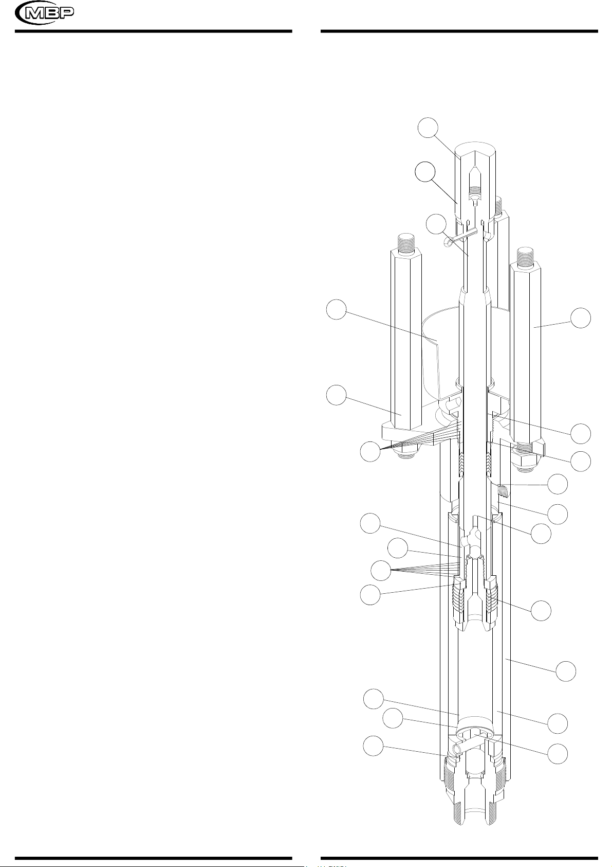
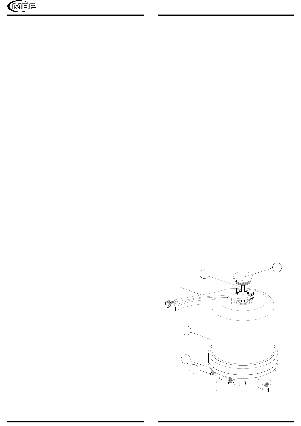
RESTARTINGA STALLED AIR MOTOR .
To reseat the air transfer valves and restart a stalled air
motor, relieve the air supply pressure to the motor by closing
the air valve. If the air transfer valves fail to reseat, screw the
cap nut (1) out of the cylinder (3), pull up on the trip rod (7)
and screw the cap nut back into the cylinder. See fig.6. Be sure
the air supply pressure is less than 12 bar (180 psi) before
opening the air valve.
DISASSEMBLING AND REASSEMBLING THE AIR
MOTOR.
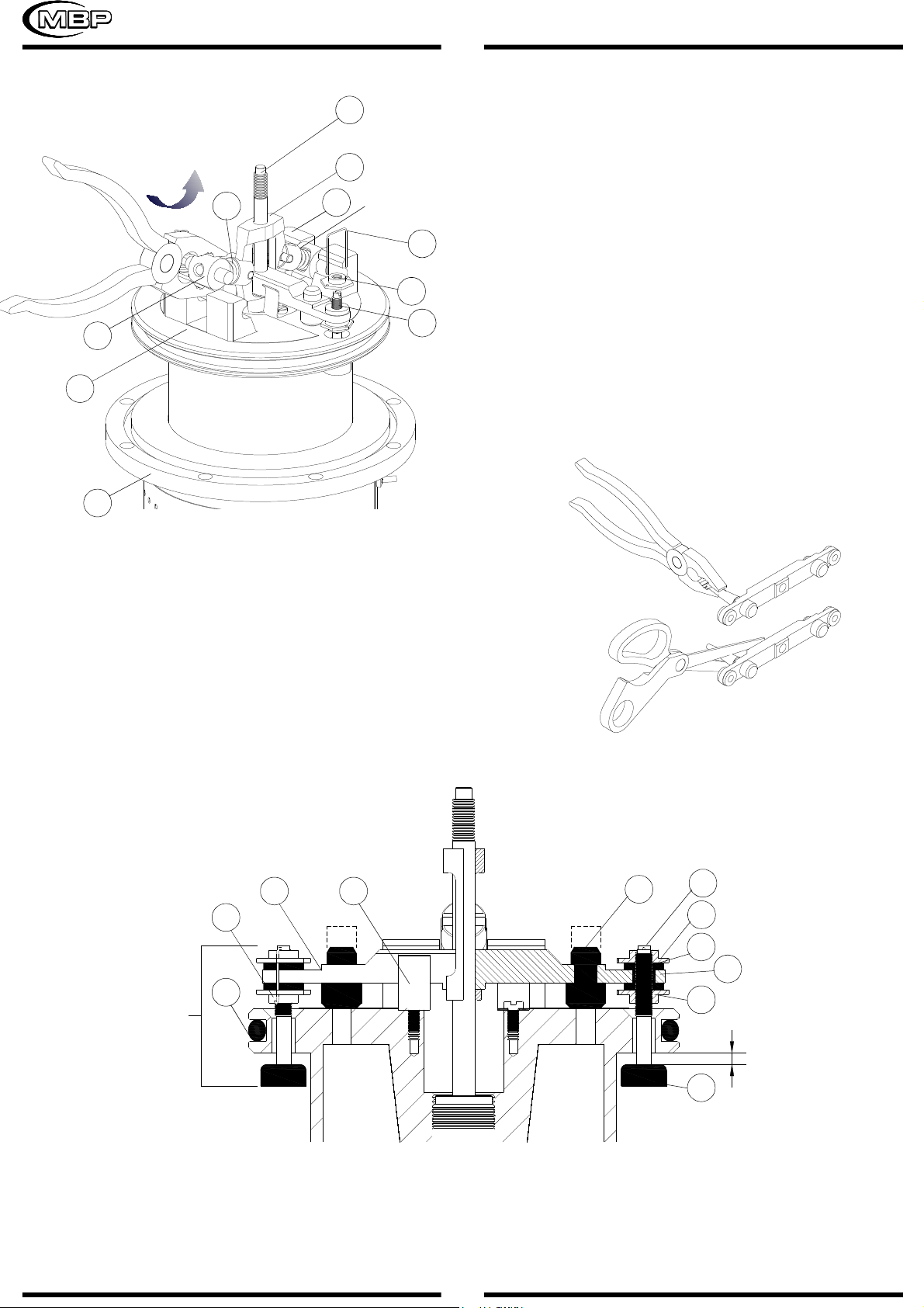
Manually push on the piston rod to move the piston to
the top of its stroke. Screw the cap nut (1) out of the cylinder
(3). Pull up on the cap nut, grip the trip rod (7) with padded
pliers (A-A) and screw the cap nut off of the trip rod. See fig. 6.
Do not damage the plated surface of the trip rod.
Damaging the surface of the trip rod can result in erratic air
motor operation.
Remove the screws (19) holding the cylinder (3) to the
base (18) and carefully pull the cylinder straight up off of the
piston. See drawing 6. Always keep fingers clear of the toggle
assemblies (X), to avoid pinching or amputating them.
Use a screwdriver to push down on the trip rod yoke
(6) and snap the toggle assemblies (X) down. Remove the
lockwires (24) and upper adjusting nuts (25) from the air
transfer valves (H). Screw the valve stems (11) out of the
grommets (27) and lower adjusting nuts (25) and inspect them
for cracks. See fig. 7.
Grip the toggle rocker (21) with pliers, compress the
spring (22) , swing the toggle assembly (X) up and away from
the piston lugs (10) and remove the parts. See fig. 7. Inspect
the valve actuator (5) to be sure it is supported by the spring
clips (9), but slides into them easily. Remove the trip rod yoke
(6), valve actuator (5) and the trip rod (7). Check the exhaust
valve poppets (28) for cracks. Pull the piston (10) up out of
the base (18) and inspect the o-ring (12) in the base casting
(10).
To remove the exhaust valve poppets (28), stretch them
out and cut them with a sharp knife.
Clean all parts thoroughly and inspect for wear or
damage. Replace parts as necessary. Inspect the polished
surfaces of the piston, piston rod and cylinder walls for scratches
or wear. Lubricate all parts with a light waterproof grease. Be
sure the o-rings are in place, slide the piston rod down through
the troat bearing and lower the piston (10) into the base (18).
1
7
3
(A-A)
19
18
(fig. 6)

9
7
6
10
24
25
11
22
21
(X)
18
10
(fig. 7)
Pull the exhaust valve poppets (28) into the valve actuator
(5) and clip off the top part shown with dotted lines. See fig. 8
and 9. Reassemble the valve stems (11), grommets (27),
adjusting nuts (25) trip rod (7), valve actuator (5), trip rod yoke
(6) and the toggle assemblies (X) on the piston (10). See fig. 8.
Adjust the valve stems (11) so there is a 4,17 mm.
clearance between the valve poppets (11) and the piston (10)
when the toggle assemblies are in the down position. See fig. 8.
Be sure the toggle assemblies (X) are in the up position
and then reinstall the cylinder (3) and the cap nut (1).See fig. 6.
Reassemble the air motor to the displacement pump. Before
mounting the pump, connect an air hose to the air motor and
run the pump to be sure it operates smoothly.
28 11
25
27
5
25
11
95
24
12
(H)
(fig. 8)
4,17mm
(fig. 9)

TROUBLESHOOTING GUIDE
Restricted line or inadequate air supply.
Insufficient air pressure, closed or clogged air valves, etc.
Exhausted fluid supply.
Obstructed fluid hose, gun or dispensing valve.
Clogged spray tip or filters.
Clogged filters.
Throat packings nut too tight or to loose.
Exhausted fluid supply.
Obstructed fluid hose or gun.
Worn spray tip.
Held open or worn intake valve.
Held open or worn fluid piston or packings.
Exhausted fluid supply.
Check valves need adjustment.
Held open or worn intake valve.
Held open or worn fluid piston or packings.
100-150
200-250
300-350
100-150
200-250
300-350
100-150
200-250
300-350
100-150
200-250
300-350
100-150
200-250
300-350
100-150
200-250
300-350
.021’’
21.20
21.40
21.60
.023’’
23.20
23.40
23.60
.025’’
25.20
25.40
25.60
.027’’
27.20
27.40
27.60
.029’’
29.20
29.40
29.60
.031’’
31.20
31.40
31.60
0.30
0.45
0.64
0.87
1.13
1.36
1.74
2.08
2.49
2.91
3.33
3.86
100-150
200-250
300-350
100-150
200-250
300-350
100-150
200-250
300-350
100-150
200-250
300-350
100-150
200-250
300-350
100-150
200-250
300-350
.009’’
9.20
9.40
9.60
.011’’
11.20
11.40
11.60
.013’’
13.20
13.40
13.60
.015’’
15.20
15.40
15.60
.017’’
17.20
17.40
17.60
.019’’
19.20
19.40
19.60
0.48 MM. 0.43 MM. 0.38 MM. 0.33 MM. 0.28 MM. 0.23 MM.
0.79 MM. 0.74 MM. 0.68 MM. 0.63 MM. 0.58 MM. 0.53 MM.
ORIFICE SIZE
MM / INCHES
FLOW IN
LITRES / MIN
FAN WIDTH AT
300 MM.
ORIFICE SIZE
MM / INCHES
FLOW IN
LITRES / MIN
FAN WIDTH AT
300 MM.
STANDARD SPRAY TIPS
Clear, increase air.
Open, clean.
Refill; purge all air from pump and fluid lines.
Clear.
Clear or replace.
Clear or replace.
Adjust.
Refil and prime.
Clear.
Replace.
Clear.
Clear or replace.
Refill and prime.
Adjust.
Clear.
Clear or replace.
PROBLEM POSSIBLE CAUSE SOLUTION
Pump. fails
to operate.
Pump operates
but output low
on down stroke.
Erratic or
accelerated
operating.
For trouble free operation is absolutely essential that your sprayer be kept clean and free of residual paint buil-up on the internal parts. It
must be cleaned and lubricated after each use.
10
TECHNICAL DATA
RECOMMENDED MAXIMUMAIR SPEED: 60 CYCLES/MIN.
FLOWAT 60 CYCLES/ MIN.: 2,3 LITRES/MIN.
PUMP RATIO: 15:1.
RECOMMENDEDAIR PRESSURE: FROM 2 TO 8 BAR.
MAXIMUM WORKING PRESSURE: 125 BAR.

MBP, S.L.
e-mail:info@mbpspray.com www.mbpspray.com
WARRANTY
1.-
2.-
3.-
M.B.P., will any repairs necessary during the first 12 months after purchase of a new unit, with the exceptions shown
under 1 and 2 below, and under the conditions shown in item 3.
In no case will M.B.P.liability extend beyond repair or repalacement of the equipment. Such liability is limited to the
amount of the original purchase price paid for the unit, minus a reasonable deduction for the time the unit has been in
service. It is the responsibility of the purchaser under this warranty to ship or deliver the failed paint sprayer to the
authorized service center at the purchaser’s expence. Parts or components covered under this warranty may either
be repaired or replaced at M.B.P. option.
Equipent not covered by M.B.P. warranty. Accessories or components of equipment sold by M.B.P. that are nort
manufactured by M.B.P. are subject to the warranty, if any, of their manufacturer. M.B.P. will provide purchaser with
reasonable assistance in making such claims.
The Industry Department of The Basque Goverment, states that all electric and pneumatic airless equipment
manufacture by M.B.P. S.L., follows the ’’CE’’ standards under the number 83/392/CEE.
MODELO / MODEL BUD - 15
Este producto cumple con la siguiente directiva de la Comunidad Europea.
This Product complies with the following European Comunity Directive.
Directiva 2014/34/EU Atex sobre máquinas. (Ex II 2G c T6 X)
Machinery Directive 2014/34/EU Atex Directive. (Ex II 2G c T6 X)
APROBADO POR /
APPROVED BY AITOR ORTIZ
FECHA / DATE
MBP, S.L. figura inscrita en el Registro Industrial del País Vasco con el Nº 01/8030 y cumple los
requisitos para el desarrollo de su actividad comercial.
MBP, S.L. is registered in the Industrial Register of the Basque Country with the Nº 01/8030.
DECLARACION DE CONFORMIDAD ‘’CE’’
‘’EC’’DECLARATION OFCONFORMITY
Damage caused by external abuse, customer negligence, or failure to operate the unit in accordance with the
instructions supplied with the unit.
Normal maintenance items.
Within the first 12 months after purchase, M.B.P. will pay 100% of the cost of covered repairs.
IMP 016-JANUARY 2022
This manual suits for next models
1
Table of contents
Other mbp Paint Sprayer manuals