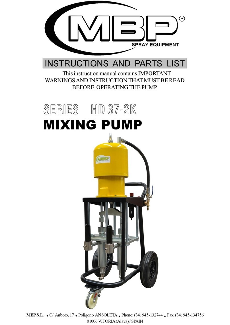
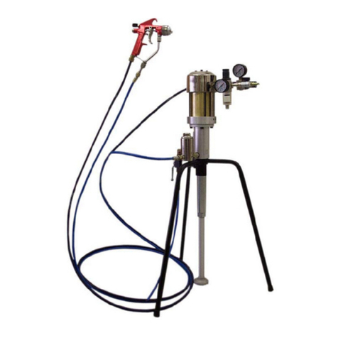
mbp MAGNUS 8000 HYDRAULIC Datasheet

MBPS.L. C/.Anboto,17 Poligono ANSOLETA Phone:(34)945-132744 Fax.
(34)945-134756
01006 VITORIA(Alava) / SPAIN P.O. BOX 3144
This instruction manual contains IMPORTANT
WARNINGSANDINSTRUCTIONTHATMUSTBEREAD
BEFORE OPERATINGTHEPUMP
INSTRUCTIONS AND PARTS LIST
MAGNUS
8 0 0 0
HYDRAULIC
SPRAY EQUIPMENT

INDEX:
SAFETY WARNINGS ................................................
OPERATION .........................................................
CLEANUP .........................................................
MAINTENANCE .........................................................
TROUBLESHOOTING GUIDE .............................
TECHNICAL DATA ................................................
PARTS DRAWING AND LIST .............................
ACCESORIES ................................................
STANDARD SPRAY TIPS .......................................
WARRANTY ........................................................
2
4
6
7
9
10
10
14
15
16
2
SAFETY WARNINGS
ATTENTION
This equipment generates very high fluid pressure. High
pressure spray can cause serious injury. Read and understand
all instructions beforeoperating.
Never point the spray gun at anyone or at any part of the body.
Never put hand, fingers over the spray tip.
Always have the tip guard in place on the spray gun while
spraying.
High pressure fluid in the hoses can be very dangerous. If the
hose develops a leak, split or rupture due to any kind of wear,
damage or misuse, the high pressure spray emitted from it can
cause a fluid injection injury or other serious bodily injury or
properly damage.
Never use a damaged hose
Tighten all fluid connections securely before each use. High
pressure fluid can dislodge a loose coupling or allow high
pressure spray to be emitted from the coupling.
Proper hose grounding continuity is essential to maintaining a
grounded spray system.
If any fluid appears to penetrate your skin, get emergency
medical care at once. Do not treat as a simple cut. Tell the
doctor exactly what fluid was injected.
All chemicals used in the pump must be compatible with the
wetted parts of the pump.
PRESSUREHAZARD
This pump can develope 240 bar working pressure. Be sure
that all spray equipment and accesories used are rated to
withstand this pressure. Do not exceed the maximum working
pressure of any component or accessory used in the system.
FIREOREXPLOSIONHAZARD
Static electricity is created by the flow of fluid through the
pump and hose. If every part of the spray equipment is not
properly grounded, sparking may occur and the system may
become hazardous. Sparking may also occur when plugging in
or unplugging a power supply cord. Sparks can ignite fumes
fromsolventsandthefluidbeingsprayed,dustparticles,whether
you are spraying indoors or outdoors, and can cause a fire or
explosion.

3
PRESSURERELIEFPROCEDURE
Toreducetheriskofseriousbodilyinjury,includingfluidinjection,
splashing fluid or solvent in the eyes or on the skin, or injury
from moving parts or electric shock, allways follow this
procedure whenever you shut off the sprayer, when checking
or servicing any part of the spray system, when installing,
cleaningorchangingspraytips,andwheneveryoustopspraying:
GASOLINEENGINESAFETY
If you experience any static sparking or even a slight shock
while using the equipment, stop spraying immediately. Check
the system for proper grounding. Do not use the system again
until the problem has been identified and corrected.
GASENGINE(WHEREAPPLICABLE)
Always place pump outside of structure in fresh air. Keep all
solvents away from the engine exhaust. Never fill fuel tank
with a running or hot engine. Hot surface can ignite spilled
fuel.Always attach ground wire from pump unit to a grounded
object, such as a metal water pipe. Refer to engine owner’s
manual for complete safety informacition.
·Engage the gun safety latch
·Turn the ON/OFF switch to OFF (red)
·Unplug the power supply cord.
·Disengage the gun safety latch. Hold a metal part of the
gun to the side of a grounded metal pail, and trigger the
gun to relieve pressure.
·Engage the gun safety latch
·Open the pressure drain valve, having a container ready
to catch the drainage
GROUNDINGINSTRUCTIONS
Electric models must be grounded. In the event of an electrical
short circuit, grounding reduces the risk of electric shock by
providing an escape wire for the electric current. This product
is equipped with a cord having a grounding wire with an
appropiate grounding plug. The plug must be plugged into an
outlet thas is properly installed and grounded in accordance
with all local codes and ordinances.
DANGER -Improper installation of the grounding plug can
result in a risk of electric shock. If repair or replacement of the
cord or plug is necessary, do not connect the green grounding
wiretoeitherflatbladeterminal.Thewirewithinsulationhaving
a green outer surface with or without yellow stripes is the
grounding wire and must be connected to the grounding pin.
·Honda engines are designed to give safe and dependable
service if operated according to instructions. Read and
understand the Honda Owner’s Manual before operating
the engine. Faiture to do so could result in personal injury
or equipment damage.
·Topreventfirehazardsandto provideadequateventilation,
keep the engine at least 1 meter (3 feet) away from
buildings and other equipment during operation. Do not
place flammable objects close to the engine.
·Children and pets must be kept away from the area of
operation due to a possibility of burns from hot engine
components or injury fromany equipment the engine may
be used to operate.
·Know how to stop the engine quickly, and understand the
operation of all controls. Never permit anyone to operate
the engine without proper instructions.
·Gasoline is extremely flammable and is explosive under
certainconditions.
·Refuel in a well-ventilated area with the engine stopped.
Do not smoke or allow flames or sparks in the refueling
area or where gasoline is stored.
·Do not overfill the fuel tank. After refueling, make sure
the tank cap is closed properly and securely.
·Be careful not to spill fuel when refueling. Fuel vapor or
spilled fuel mayignite. If any fuel isspilled, make sure the
area is dry before starting the engine.
·Never run the engine in a enclosed or conined area.
Exhaust contains poisonous carbon monoxide gas;
exposure may cause loss of consciousness and may lead
to death.
·The muffler becomes very hot during operation and
remains hot for a while after stopping the engine. Be
careful not to touch the muffler while it is hot. To avoid
severe burns or fire hazards, let the engine cool before
transporting it or storing it indoors.
·Never ship/transport unit with gasoline in the tank.
NOTE:
Before starting to workthe pump must be connected to ground.
The pump must be connected to ground with a ground wire
whichis suppliedwiththepump(4mm2 of section and a clamp).

4
OPERATION
-Attach and airless spray gun to the spray hose. Do not attach
the tip to the spray gun yet. Remove the tip if it is already
attached.
-Check the hydraulic fluid level daily before starting the unit.
The hydraulic fluid level should be at the‘’Full’’mark,onthe
dipstick.
-For gasmodels, checkthe engine oil level dailybeforestarting
the unit. The gasoline engine oil level is determined by the
engine manufacturer.
- Place the suction pipe into a container of solvent/water.
- Place the bleed hose into a metal waste container.
- Set the pressure to minimum by turnig the pressure control
knobfully counterclockwise.
- Open the hydraulic shut-off valve located on the hydraulic
pressure hose. The handle should be in line with the hose.
- Open the bleed valve by turning it fully counterclockwise.
- Start the engine or turn on the electric motor.
a) To start the gas engine.
b) To turn off the electricmotor.
Move the fuel valve lever to the open position
Move the throttle lever to its middle point
Move the choke lever to the closed position for a
cold engine or to the open position for a warm
engine.
Turn the engine switch to the ON position
Pull the starter rope briskly until the engine starts.
b) To start the electric motor, move the ON/OFF switch
to the ON position
- Turn the pressure control knob clockwise approximately 1/3
of the way down to increase pressure until the sprayer cycles
evenly and solvent flows freely from the bleed hose.
- Allow the sprayer to run for 15-30 seconds to flush the test
fluid out through the bleed hose and into the waste container.
- Turn off the unit
a) To turn off the gas engine
Set the pressure to minimum by turnig the
pressure control knob fully conterclockwise.
Move the throttle lever to the slow position.
Turn the engine switch to the OFF position.
C A U T I O N
Set the pressure to minimum by turnig the
pressure control knob fully counterclockwise.
Move the ON/OFF switch to the OFF position.
PREPARINGTOPAINT
Before painting, it is important to make sure that the fluid in
the system is compatible with the paint that is going to be used.
NOTE:
Incompatible fluids and paint may cause the valves to
become stuck closed, which would require disassembly
and cleaning of the sprayer´s fluid suction.
Always keep the trigger lock on the spray gun in
the locked position while preparing the system.
- Place the suction pipe into a container of the appropiate
solvent.
NOTE:
If you are spraying a water-based latex, flush with warm,
clean water. If you are using any other material, check
with the material manufacturer for a compatible solvent.
Move the fuel valve lever to the open position
Move the throttle lever to its middle point
Move the choke lever to the closed position for a
cold engine or to the open position for a warm
engine
Turn the engine switch to the ON position
Pullthestarter ropebrisklyuntiltheenginestarts.
- Place the bleed hose into a metal waste container.
- Set the pressure to minimum by turnig the pressure con-
trol knob fully counterclockwise.
- Open the hydraulic shut-off valve located on the hydraulic
pressure hose. The handle should be in line with the hose.
- Open the bleed valve by turnig it fully counterclockwise.
- Start the engine or turn on the electric motor.
a) To start the gas engine.
b) To start the electric motor, move the ON/OFF
switch to the ON position

5
- Turn the pressure control knob clockwise approximately
1/3 of the way down to increase pressure until the sprayer
cycles evenlyand solvent flows freely fromthe bleed hose.
- Allow the sprayer to run for 15-30 seconds to flush the
test fluid out through the bleed hose and into the waste
container.
- Turn off the unit
a) To turn off the gas engine
PAINTING
Set the pressure to minimum by turnig the
pressure control knob fully conterclockwise.
Move the throttle lever to the slow position.
Turn the engine switch to the OFF position.
b) To turn off the electric motor.
Set the pressure to minimum by turnig the
pressurecontrolknobfullycounterclockwise.
Move the ON/OFF switch to the OFF
position.
NOTE: Make sure that the spray gun does not have a
tip or tip guard installed.
- Close the bleed valve by turning it fully clockwise.
- Start the engine or turn on the electric motor.
- Turn the pressure control knob clockwise approximately
1/3 of the way down to increase pressure.
- Unlock the gun by turning the gun trigger lock to the
unlockedposition.
-Trigger the gun into the metal waste container until the old
solvent is gone and fresh solvent is coming out of the gun.
- Lock the gun by turning the gun trigger lock to the locked
position.
- Set down the gun and increase the pressure by turning the
pressure control knob slowly clockwise.
- Check the entire system for leaks. If leaks occur, follow
the ‘’Pressure Relief Procedure’’ in this manual before
tighteningany fitting or hoses.
- Follow the ‘’Pressure Relief Procedure’’ in this manual
before changing from solvent to paint.
WAR N I N G
Be sure to follow the pressure relief procedure
when shutting the unit down for any purpose,
includingservicingoradjustinganypartofthespray
system,changingorcleaningspraytips,orpreparing
for cleanup.
- Place the suction pipe into a container of paint.
- Place the bleed hose into a metal waste container.
-Setthepressure tominimumby turnigthepressurecontrol
knobfully counterclockwise.
-Open the hydraulic shut-offvalve located on thehydraulic
pressure hose. The handle should be in line with the hose.
- Open the bleed valve by turnig it fully counterclockwise.
- Start the engine or turn on the electric motor.
a) To start the gas engine.
Move the fuel valve lever to the open position
Move the throttle lever to its middle point
Move the choke lever to the closed position for a
cold engine or to the open position for a warm
engine
Turn the engine switch to the ON position
Pullthe starter rope briskly until the engine starts.
b) To start the electric motor,move the ON/OFf switch
to the ON position
- Turn the pressure control knob clockwise approximately
1/3 of the way down to increase pressure until the sprayer
cycles evenly and paint flows freely from the bleed hose.
- Turn off the unit
a) To turn off the gas engine.
Set the pressure to minimum by turnig the
pressure control knob fully conterclockwise.
Move the throttle lever to the slow position.
Turn the engine switch to the OFF position.
b) To turn off the electric motor.
Set the pressure to minimum by turnig the
pressure control knob fully counterclockwise.
Move the ON/OFF switch to the OFF position.
- Remove the bleed hose from the waste container and
place it into the container of paint.
- Close the bleed valve by turning it fully clockwise.
- Start the engine or turn on the electric motor.
- Turn the pressure control knob clockwise approximately
1/3 of the way down to increase pressure.
- Unlock the gun by turning the gun trigger lock to the
unlockedposition.

6
PRESSURERELIEFPROCEDURE
-Trigger the gun into the metal waste container until all air
and solvent is flushed from the spray hose and paint is
flowing freely from the gun.
- Lock the gun by turning the gun trigger lock to the locked
position.
- Turn off the unit.
-Attach tip guard and tip to the gun as instructed by the tip
guard or tip manuals.
Ground the gun by holding it against the edge of
the metal container while flushing. Failure to do
so may lead to a static electric discharge, which
may cause a fire.
WAR N I N G
WAR N I N G
POSSIBLE INJECTION HAZARD. Do not spray
without the tip guard in place. Never trigger the
gun unless thetipisineitherthesprayortheunclog
position.Alwaysengagetheguntrigger lockbefore
removing, replacingor cleaning tip.
-Star the engine or turn on the electric motor.
-Increase the pressure by turning the pressure control knob
slowly clockwise and test the spray pattern on a piece of
cardboard.Adjust the pressure control knob until thespray
from the gun is completely atomized.
WAR N I N G
Be sure to follow the pressure relief procedure
when shutting the unit down for any purpose,
including servicing or adjusting any part of the
spray system, changing or cleaning spray tips, or
preparing for cleanup.
NOTE:
Turning the pressure up higher then needed to atomize
the paint will cause premature tip wear and additional
overspray.
-Lock the gun byturning the guntrigger lock to the locked
position.
- Turn off the unit
a) To turn off the gas engine
Setthepressuretominimumbyturnigthepressure
control knob fullyconterclockwise
Move the throttle lever to the slow position
Turn the engine switch to the OFF position.
b) To turn off the electric motor.
Setthepressuretominimumbyturnigthepressure
control knob fully counterclockwise.
Move the ON/OFF switch to the OFF position.
- Close the hydraulic shut -off valve on the hydraulic
pressure hose.
- Unlock the gun by turning the gun trigger lock to the
unlockedposition.
-Hold the metal part of the gun firmly to the side of a metal
waste container to ground the gun and avoid a build up of
static electricity.
-Trigger the gun to remove any pressure that may still be in
the hose.
-Lock the gun byturning the guntrigger lock to the locked
position.
- Place the bleed hose into the metal waste container.
- Open the bleed valve by turnig it fully counterclockwise.
CLEANUP
Special cleanup instructions for use with
flammablesolvent:
- Always flush spray gun preferably outside and at least
one hose length from spray pump.
-Ifcollecting flushedsolventsinaonegallonmetalcontainer,
place it into a empty five gallon container, then flush
solvents.
- Area must be free of flammable vapors.
-Follow all cleanupinstructions.
WAR N I N G

7
The sprayer, hose, and gun should be cleaned
thoroughlyafterdailyuse.Failureto dosopermits
material to build up, seriously affecting the
performance of the unit.
Always spray at minimum pressure with the gun
nozzle tip removed when using mineral spirits or
any other solvent to clean the sprayer, hose, or
gun. Static electricity buildup may result in a fire
or explosion in the presence of flammable vapors.
-Follow the ‘’Pressure Relief Procedure’’ found in the
Operation section of this manual.
-Remove the gun tip and tip guard and clean with a brush
using the appropriate solvent.
-Place the suction pipe into a container of the appropriate
solvent.
Use only compatible solvents when cleaning out
oil based enamels, lacquers, coal tar, and epoxies.
Check with the fluid manufacturer for the
recommended solvent.
-Triggerthe gun intothe metal waste container untill thepaint
is flushed out off the hose and solvent is coming out of the
gun.
-Continue to trigger the spray gun into the waste container
untill the solvent coming out of the gun is clean.
Cleaning a Clogged Tip
-Place the bleed hose into the metal waste container.
-Setthepressuretominimumbyturningthepressurecontrol
knob fully countercockwise.
-Open the hydraulic shut-offvalve located on thehydraulic
pressure hose. The handle should be in line with the hose.
-Open the bleed valve by turning it fullycounterclockwise.
-Start the engine or turn on the electric motor.
-Allow the solvent to circulate through the unit and flush
the paint out of the bleed hose into the metal waste
container.
-Turn off the unit.
-Close the bleed valve byturningit fully clockwise.
-Star the engine or turn on the electric motor.
NOTE: For long-term or cold weather storage, pump
mineral sprits through the entire system.
-Follow the ‘’Pressure Relief Procedure’’ found in the
Operation section of this manual.
-Store the unit in a clean, dry area.
Do not store the unit under pressure.
1- Follow the ‘’Pressure Relief Procedure’’ in the Operation
section on this manual.
2- In the tip clogs, rotate the tip handle 180º until the arrow on
the handle is facing the opposite of the spray direction and
the handle clicks in the reverse position.
3- Trigger the gun once so that the pressure can blow the clog
out. NEVER use the tip in the reverse position for more
than ONE trigger pull at a time. This procedure can be
repeated until the tip is free of clogging.
WAR N I N G
Theflowfromthespraytipisatveryhighpressure.
Contac with any body part may be dangerous. Do
not place finger on gun outlet. Do not point the gun
at anyperson. Never operate the spray gun without
the proper tip guard.
MAINTENANCE
WAR N I N G
Before proceeding, follow the Pressure Relief
Procedure outlined previously in this manual.
Additionally, follow all other warnings to reduce
the risk of an injection injury, injury from moving
parts or electric shock.Always unplug the sprayer
before servicing.
C A U T I O N
WAR N I N G
WAR N I N G
Ground the gun by holding it against the edge of
the metal container while flushing. Failure to do
so may lead to a static electric discharge, which
may cause a fire.
C A U T I O N

MAINTAINING THE HYDRAULIC
SYSTEM
DAILYMAINTENANCE
Two daily procedures are required for routine operator
maintenance on this unit:
-Lubricating the upper packing.
-Cleaning the rock catcher.
Lubricating the Uper Packings
-Clean out the paint that has seeped past the upper
packings into the packing oil reservoir above the fluid
section.
-Fill the packing oil reservoir 1/2 full with Piston Lube
supplied by the factory. This will extend packing life.
NOTE: Do not over -fill the reservoir so that it overflows
and drips into the paint.
8
Use of MBP Hydraulic Fluid is mandatory in the
hydraulic system. Do not use any other hydraulic
fluid.Useofanyotherhydraulicfluidmayseriously
damage the hydraulic system and will void the
warranty.
1- Checkthehydraulicfluiddaily.Itshouldbeatthe‘’Full’’mark
on the dipstick. If it is low, add only MBP Hydraulic Fluid.
Never add or change hydraulic fluid except in a clean,
dust-free area. Contamination of the hydraulic fluid will
shorten hydraulic pump life and may void warranty.
2- Change the hydraulic fluid every twelve months. Drain the
old fluid from the tank.Start the unit atjust enough pressure
to operate the fluid section. Run theunit at this low pressure
for at least 5 minutes. This removes air from the system.
Check the fluid level after this procedure.
3- The hydraulic system has an external, replaceable hydraulic
filter. Change the filter every twelve months.
BASICENGINEMAINTENANCE
(GASENGINE)
-For detailed engine maintenance and technical specifications
refer to the separate gasoline engine manual.
-All service tothe engineshould beperformed byan authorized
Honda Power Equipment dealer.
Daily
-Check engine oil level, and fill as necessary.
-Check gasoline level, and fill as necessary.
WAR N I N G
Alwaysfollowthefuelingprocedureoutlinedearlier
in this manual.
First 20 Hours
1º Change engine oil.
Every 100 Hours
1º Change engine oil.
2º Clean the sediment cup.
3 ºClean and re-gad the spark plug.
4º Clean the spark arrestor.
Weekly
Remove the air filter cover and clean the element. In very
dustyenvironments,check the filter daily. Replace the element
as needed. Replacement elements can be purchased from your
local Honda dealer.
Engine Operation and Service
1º Clean and oil airfilter pad ongasoline engine every25 hours
or once weekly. Do not permit the air intake screen around
the fly wheel of the gas engine to load up with paint or trash.
Clean it regularly. The service life and efficiencyof the gas
engine model depends upon keeping the gasoline engine
running properly. Change the oil in the engine every 100
hours. Failure to observe this may result in engine
overheating. Consult the engine manufacturer’s service
manualprovided.
2º To conserve fuel, service life, and efficiency of the unit,
always operate the gasoline engine at the lowest RPM at
which it runs smoothly without laboring and delivers the
amountrequired fortheparticularpaintingoperation.Higher
RPM does not produce higher working pressure. The
gasolineengineisconnectedtothehydraulicpumpbyapulley
combination designed to produce full paint delivery of 1.2
GPM at maximum RPM
3ºThewarrantyongasolineenginesorelectricmotorsislimited
to the original manufacturer
C A U T I O N

9
TROUBLESHOOTINGGUIDEFLUIDSECTION
Lower foot valve ball is not seating due to
trash or wear.
Material too viscous to siphon.
Air leaking in on siphon side or damaged
siphon hose. Siphon may be too small for
heavymaterial.
Upper ball is not seating due to trash or
wear.
Lower packing set is worn.
Material container is empty or material is
too thick to flow through siphon hose.
Bottom ball stuck to foot valve seat.
Siphon hose is kinked or loose.
Loose connections. Bleed valve is open
partially or bleed valve is worn. Lower
packing seat is worn.
Upper and/or lower ball not seating.
Spray tip is worn.
Outlet filter or gunfilter is clogged.
Low voltage and/or inadequate
amperange.
Hose size orlengthis too smallor too long.
Solventhascausedupperpackingto swell.
Remove foot valve assembly. Cleanand inspect. Test foot valve
by fillingwith water; if ball fails to seal the seat, replace ball.
Thin material, contact manufacturer for proper thinning
procedures.
Tighten all connections between pump and paint container. If
damaged, replace. Switch to larger diameter siphon set.
Check upper seat and ballwithwater. If ballfails to seal, replace
seat.
Replace packing set if worn.
Refill with new material. If too thick, remove siphon hose,
immerse fluid sectionin material, and start pump to prime.Add
thinner to material.Change to bigger siphon set. Open bleed
valve to remove air and restart pump.
Remove foot valve. Clean ball and seat.
Straighten.
Check all connections between pump and gun. Tighten as
necessary. If material is flowing from bleed hose, close bleed
valve or replace, if necessary. Should none of the above be
evident, replace lower packing.
Reseat balls by cleaning.
Replace.
Cleanorreplacefilter.
Check electrical service.Correct as required.
Increase hose size to minimize pressure drop through hose
and/or reduce hose length.
Replace packing.
TROUBLE POSSIBLE CAUSE SOLUTION
Pump delivers on
upstroke only or goes
up slowly and down
fast.
Pump delivers on
down stroke only or
goes up fast and
down slowly.
Pump moves up and
down fast, delivering
material.
Pump moves up and
down slowly when
spray gun is shut off.
Not enough fluid
pressure at gun.
Pump chatters on up
or down stroke.
TROUBLESHOOTINGGUIDEFLUIDSECTION
Fluid pump piston seat unthreaded.
Valve sticking or oil motor trip rod shifter
assembly separated.
Valvesticking.
Broken spring retainer (valve rod
assembly).
Broken spring or valve rod.
Air in hydraulic motor.
Air influid pump.
If connecting rod is okay, remove cylinder head plug and pop
valve down. Replace plug and start machine. If machine cycles
up and stops at bottom again, then problem is piston seat on
fluid pump. Check piston seat.Repair or replace as necessary. If
piston seatis okay and problemdoes not change, check oil motor.
Remove valve and check for scratches and rough movement
when sliding it up and down. Replace valve and spool in this
condition. Check trip rod for possible separation and spool in
this condition. Check trip rod for possible separation.
Remove valve and check for scratches and rough movement
when sliding it up and down. Replace valve and spool in this
condition.
Replace valve rod assembly.
Replace valve rod assembly
Reset valve. Purge Air, generally accomplished by low pressure
cycling of motor/pump assembly for 5-10 minutes.
Check for causes of air introduction:
-Loose fittings in tank.
-Loose fittings on hydraulic pump.
-Loose hose connections.
-Lowoilin reservoir.
Stall at top can occur randomly when fluid pump picks up air.
Reset valve.Avoid air in the fluid pump.
TROUBLE POSSIBLE CAUSE SOLUTION
Oil motor stalls at
bottom (no unusual
heat problems).
Oil motor stalls at top
(no unusual heat
problems).

ON/OFF
SWITCH
PUMP
DRAINVALVE
MOTOR:
ELECTRIC(MAGNUS8000)
GASHONDA5.5HP(MAGNUS8000GAS)
TROLLEY
HYDRAULICTANK
PRESSURE
CONTROL
FILTER INLETHYDRAULICSYSTEM
OUTLETHYDRAULICSYSTEM
HYDRAULICFLUID
LEVEL
10
MAGNUS8000
•Delivery: 5,7 l/min.
•Max. Pressure: 228bar
•Max.Tip Size: 1gun-0,036’’
2guns-0,026’’
•Electric Motor 3HP (220V-50Hz.)
•Weight: 66 Kgs.
•Packagingdimesions:84x120x108cm.
•Delivery: 6,4 l/min.
•Max. Pressure: 228bar
•Max.Tip Size: 1gun-0,043’’
2guns-0,033’’
•Motor: Gasoline 5,5HP
•Weight: 72Kgs.
•Packagingdimesions:84x120x108cm.
PARTS LIST
TECHNICAL DATA
HYDRAULICSHUT-OFF
VALVE
GROUND
101.400.00
WIRE GROUND
101.620.00

11
MOTOR 1
2
8
34
33
3
45
6
7
10
9
14
12
11
15
16
17
18
19
22
31
17
20
21
24
23
25
32
27
28
26
29
30
13
PLUG
O-RING
CYLINDER
BALL
SPRING
0-RING
PLUG
NIPPLE
NUT
VALVE
SHAFT
DISTRIBUTOR
O-RING
WASHER
WASHER
NUT
O-RING
CYLINDER
NUT
JOINT
BASE CYLINDER
JOINT
BODY CYLINDER
PIN
SPRING
NIPPLE
JOINT
CONECCTOR
NUT
VALVE
GUIDE
NIPPLE
PIPE
ELBOW
103.110.04
CJT.162
103.110.01
CB0.009
103.110.03
CJT.161
103.110.02
103.200.01
CTU.107
103.120.02
103.120.00
103.110.05
CJT.163
103.110.06
CAR.127
103.120.06
CJT.160
103.100.02
103.100.01
CAB.021
103.121.00
CAB.020
103.300.01
103.120.08
103.300.02
G.500.04
CJT.176
CNA.128
CNA.121
CNC.018
103.100.08
CNA.151
103.200.02
CNA.150
1
2
3
4
5
6
7
8
9
*10
11
*12
13
14
15
16
17
18
19
20
21
22
23
24
25
26
27
28
29
30
31
32
33
34
1
1
1
2
2
2
2
1
1
1
1
1
3
1
1
1
2
1
1
1
1
1
1
1
1
2
2
1
1
1
1
1
1
1
Nº REF. DESCRIPTION Q
*KIT 060: Sold both pcs together.

12
ROD
FEMALE GLAND
PACKING
PACKING
MALE GLAND
SPRING
JOINT
CYLINDER
SPRING SEAT
SPRING
BALL
PISTON
CYLINDER
O-RING
BALL GUIDE
BALL
JOINT
VALVE
FILTER
WASHER
NIPPLE
NUT
‘’T’’
VALVE
PURGE
NIPPLE
1
*3
*4
*5
*6
7
8
9
10
11
*12
13
14
15
16
*17
18
19
20
21
22
23
24
25
26
27
104.200.06
104.240.04
104.240.01
104.240.02
104.240.03
104.200.07
104.200.08
104.200.05
104.200.02
104.200.03
CBO.102
104.230.00
104.200.04
CJT.042
104.200.01
CBO.103
104.200.09
104.220.00
104.200.10
CAR.127
CNA.126
CNA.127
CNA.100
104.251.00
104.252.00
CNA.087
1
2
6
4
2
1
2
1
1
1
1
1
1
1
1
1
1
1
1
1
1
1
1
1
1
1
Nº REF. DESCRIPTION Q
DISPLACEMENT PUMP
*KIT 049: Includes packings (up & down)
packing glands and balls.
1
22
3
4
7
6
5
8
9
8
10 11
6
3
4
13
5
12
14
18
15
17
16
19
21
20
23
24
25
2726

13
*KIT 051: Piston Pump
TANK
COVER
VALVE
JOINT
SCREW
WASHER
PLUG
SCREW
WASHER
NUT
SCREW
FILTER
PIPE
NUT
SCREW
BELT
DIPSTICK
ELBOW
PIPE
NIPPLE
1
2
3
4
5
6
7
8
9
10
11
12
13
14
15
16
17
18
19
20
104.600.01
104.620.00
104.621.00
104.600.02
CTA.011
CAR.052
104.600.14
CTA.014
CAR.006
CTU.106
CTB.013
16.313.00
104.622.00
104.600.03
CTA.015
CJT.301
CMH.002
CNA.065
104.600.04
CNA.151
1
1
1
1
10
10
1
5
8
4
2
1
1
1
1
1
1
1
1
1
Nº REF. DESCRIPTION Q
KNOP
PLATE
PULLEY
PIN
SCREW
COVER
FILTER
ELBOW
PISTON PUMP
S
UPPORT
WASHER
JOINT
NUT
HOSE
NIPPLE
HOSE
WASHER
WASHER
PIPE
NIPPLE
*21
22
23
24
25
26
27
*28
*29
30
31
32
33
34
*35
36
37
38
39
40
104.600.08
104.600.05
104.600.06
CTG.021
CTA.010
104.640.00
CMH.003
CNA.064
CMH.004
104.630.00
CAR.023
104.600.10
CTU.017
104.650.00
104.600.07
104.660.00
CAR.015
CAR.251
104.600.15
CNA.150
1
1
1
1
1
1
1
1
1
1
2
1
1
1
1
1
1
1
1
1
Nº REF. DESCRIPTION Q
9
10 30
89
8
9
15
37
7
14 13 32
28 19 29
36
35 21
5
6
23
24
16
26
22
10 9
25
1
4
2
3
40
20 39
27
34
17
18
31
11
31
9
33 38

ELECTRIC PUM
14
GASOLINE PUM
ACCESSORIES
REF 104.400.00
KIT HP+FILTER+DRAIN VALVE, WHEN SPRAYING PAINTS
PULLEY
PIN
WASHER
SCREW
WASHER
NUT
HANDLE
PLATE
MOTOR
PLUG
1
2
3
4
5
6
7
8
9
10
104.800.01
CTG.020
CAR.006
CTB.009
CAR.051
CTU.001
104.800.02
104.810.00
CEA.042
CAB.003
1
1
8
4
4
4
1
1
1
1
Nº REF. DESCRIPTION Q
PULLEY
PIN
WASHER
SCREW
WASHER
NUT
HANDLE
PLATE
MOTOR
SWITCH ON/OFF
PLUG
CABLE
SCREW
NUT
WASHER
WASHER
104.700.01
CTG.020
CAR.005
CTB.029
CAR.053
CTU.001
104.800.02
104.710.00
CEA.044
CEA.048
CAB.003
102.630.00
CTB.037
CTU.003
CAR.006
CAR.051
1
1
8
2
4
2
1
1
1
1
1
1
4
4
2
2
Nº REF. DESCRIPTION Q
1
2
3
4
5
6
7
8
9
10
11
12
13
14
15
16
6
16
14
53
815
4
1
2
9
12
10
13
3
7
11
6
6
53
8
1
2
9
3
7
10 4

15
100-150
200-250
300-350
100-150
200-250
300-350
100-150
200-250
300-350
100-150
200-250
300-350
100-150
200-250
300-350
100-150
200-250
300-350
100-150
200-250
300-350
1.36
1.74
2.08
2.49
2.91
3.33
3.86
0.48mm .019’’
19.20
19.40
19.60
0.53mm .021’’
21.20
21.40
21.60
0.58mm .023’’
23.20
23.40
23.60
0.63mm .025’’
25.20
25.40
25.60
0.68mm .027’’
27.20
27.40
27.60
0.74mm .029’’
29.20
29.40
29.60
0.79mm .031’’
31.20
31.40
31.60
ORIFICE SIZE
MM / INCHES FLOW IN
LITRES / MIN FAN WIDTH AT
300 MM.
STANDARDSPRAYTIPS
ORIFICE SIZE
MM / INCHES FLOW IN
LITRES / MIN FAN WIDTH AT
300 MM.
100-150
200-250
300-350
100-150
200-250
300-350
100-150
200-250
300-350
100-150
200-250
300-350
100-150
200-250
300-350
100-150
200-250
300-350
100-150
200-250
300-350
4.353
4.958
6.170
6.813
7.532
8.251
9.727
0.84mm .033’’
33.20
33.40
33.60
0.89mm .035’’
35.20
35.40
35.60
0.99mm .039’’
39.20
39.40
39.60
1.04mm .041’’
41.20
41.40
41.60
1.09mm .043’’
43.20
43.40
43.60
1.14mm .045’’
45.20
45.40
45.60
1.25mm .049’’
49.20
49.40
49.60
SWIVEL CONNECTOR
REF:J.274
REF:J.274X STANDARDTIP
REF:90.XX.XX
REVERSIBLE BASE
REF:J.790.00 TIPEXTENSIONS
REF:J.271.
AIRLESS GUN FILTER
MESH
50
100
200
COLOUR
WHITE
YELLOU
RED
REF.
J.260.01
J.260.02
J.260.03
J.700.CS (CARBON STEEL) =1,150Kg
J.700.AL(ALUMINIUM) =0,900Kg
J.700.CS.L (CARBON STEEL) =1,830Kg
J.700.AL.L (ALUMINIUM) =1,430Kg

MODELO / MODEL MAGNUS 8000
Este producto cumple con la siguiente directiva de la Comunidad Europea.
This Product complies with the following European Comunity Directive.
Directiva 2014/34/EU Atex sobre máquinas. (Ex II 2G c T6 X)
Machinery Directive 2014/34/EUAtex Directive. (Ex II 2G c T6 X)
APROBADO POR /
APPROVED BY AITOR ORTIZ
FECHA / DATE
MBP, S.L. figura inscrita en el Registro Industrial del País Vasco con el Nº 01/8030 y cumple los
requisitos para el desarrollo de su actividad comercial.
MBP, S.L. is registered in the Industrial Register of the Basque Country with the Nº 01/8030.
IMP 046-MARZO 2018
DECLARACIONDECONFORMIDAD‘’CE’’
‘’EC’’DECLARATIONOFCONFORMITY
MBP,S.L.
e-mail:info@mbpspray.com www.mbpspray.com
WARRANTY
1.-
2.-
3.-
M.B.P., will any repairs necessary during the first 12 months after purchase of a new unit, with the exceptions shown
under 1 and 2 below, and under the conditions shown in item 3.
In no case will M.B.P.liability extend beyond repair or repalacement of the equipment. Such liability is limited to the
amount of the original purchase price paid for the unit, minus a reasonable deduction for the timethe unit has been in
service. It is the responsibility of the purchaser under this warranty to ship or deliver the failed paint sprayer to the
authorized service center at the purchaser’s expence. Parts or components covered under this warranty may either
be repaired or replaced at M.B.P. option.
Equipent not covered by M.B.P. warranty. Accessories or components of equipment sold by M.B.P. that are nort
manufactured by M.B.P. are subject to the warranty, if any, of their manufacturer. M.B.P. will provide purchaser with
reasonable assistance in making such claims.
The Industry Department of The Basque Goverment, states that all electric and pneumatic airless equipment
manufacture by M.B.P. S.L., follows the ’’CE’’standards under the number 83/392/CEE.
Damage caused by external abuse, customer negligence, or failure to operate the unit in accordance with the
instructionssuppliedwiththeunit.
Normal maintenance items.
Within the first 12 months after purchase, M.B.P. will pay 100% of the cost of covered repairs.
Table of contents
Other mbp Water Pump manuals
Popular Water Pump manuals by other brands

Silverline
Silverline UK-917615 Original instructions

Stark
Stark 71104 Owner's manual and safety instructions

briwatec
briwatec TOPAS D004 V Translation of the operating manual

MICRODOS
MICRODOS ME1-RX Programming instructions

Samoa
Samoa 150 000 Parts and technical service guide

Rapid
Rapid 90L20/30/1 operating instructions