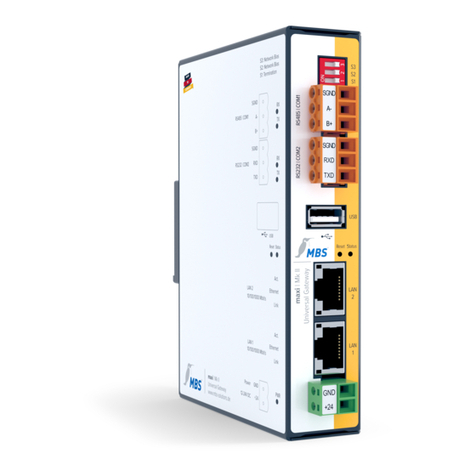
MBS UGW X Series User manual

MANUAL
Universal gateways
Date: 2022/11 Software version (firmware): V4 or higher

Table of contents
UGW X-series Introduction 2 of 66
Table of contents
1 Introduction .......................................................................................... 4
1.1 Registered trademarks......................................................................................... 4
1.2 Copyright.................................................................................................................. 4
1.3 Product support...................................................................................................... 4
1.4 Target group ........................................................................................................... 4
2 Concepts, functions and gateway design ........................................ 5
2.1 Universal gateways ............................................................................................... 5
2.2 Classification of protocols ................................................................................... 6
2.3 Function and properties of data points............................................................ 6
2.4 Mapping.................................................................................................................... 8
2.5 Configuration and project planning .................................................................10
2.6 Technical design and operating principle......................................................13
2.7 Status LED...............................................................................................................15
3 Overview of the UGW X-series .........................................................16
3.1 Type overview of the UGW X-series................................................................ 17
3.2 Casing and connections .....................................................................................18
4 Device views........................................................................................19
4.1 Front view of the UGW SINGLE-X standard...................................................19
4.2 Front view of the UGW DOUBLE-X (LON) .....................................................20
4.3 Front view of the UGW TRIPLE-X (CAN + M-Bus).........................................21
4.4 Side view................................................................................................................22
4.5 Sticker .....................................................................................................................22
4.6 Rear .........................................................................................................................22
5 Commissioning .................................................................................. 23
5.1 Hardware installation ..........................................................................................23
5.2 Configuring the UGW using the web interface............................................24
6 User interface, operation and functions......................................... 26
6.1 “General” menu....................................................................................................27
6.2 General information on the driver menu areas............................................38
6.3 “System” menu area ...........................................................................................39
6.4 BACnet menu.........................................................................................................41
6.5 MODBUS Master menu .......................................................................................51
6.6 “LONTalk” menu area.........................................................................................53
6.7 “M-Bus” menu area .............................................................................................55
6.8 “CANopen” menu area.......................................................................................59
6.9 Help menu ..............................................................................................................61
6.10 Exiting the web interface ...................................................................................65
6.11 Reset – Options....................................................................................................65

Table of contents
UGW X-series Introduction 3 of 66
7 Appendix............................................................................................. 66
7.1 FAQs........................................................................................................................66

1Introduction
UGW X-series Introduction 4 of 66
1 Introduction
Thank you for using the universal gateway (UGW). This manual describes the design, functions and
configuration of the UGW X-series family of products.
1.1 Registered trademarks
Trademarks and product names of various companies will be used in this book. The following
names are the registered trademarks of their respective manufacturers and will not be mentioned
separately in this book:
• BACnet is a registered trademark of the American Society of Heating, Refrigerating and Air-
Conditioning Engineers, INC. (ASHRAE)
• CANopen®, MODBUS® and LON® are registered trademarks of the respective trademark
owners in certain countries.
1.2 Copyright
©2020 MBS | Römerstraße 15 | 47809 Krefeld, Germany
Phone: +49 2151 7294-0
Fax: +49 2151 7294-50
E-mail: info@mbs-solutions.de
Website: www.mbs-solutions.de
All rights reserved. It is not permissible to reproduce or use electronic systems to edit, copy or
otherwise disseminate this manual or any part thereof in any form whatsoever (print, photocopy or
any other process) without prior written approval by the manufacturer.
1.3 Product support
In case of technical problems, please contact the manufacturer’s service department.
Monday to Friday: 8:30 a.m. to 12.00 p.m. and 1:00 p.m. to 5:00 p.m.
Phone: +49 2151 7294-0
Fax: +49 2151 7294-50
E-mail: support@mbs-solutions.de
Website: www.mbs-solutions.de (German)
Wiki: http://wiki.mbs-solutions.de/doku.php?id=start (German)
1.4 Target group
This manual is intended for specialists trained in control and automation technology with
experience in installing, commissioning and using gateways.
Note on disposal
In accordance with European Directive 2012/19/EU (WEEE), the devices are classified as
used electronic devices and not as domestic waste for disposal purpose. Use the
respective community collection points for disposal.

2Concepts, functions and gateway design
UGW X-series Concepts, functions and gateway design 5 of 66
2 Concepts, functions and gateway design
2.1 Universal gateways
A gateway enables communication between devices which use different communication protocols
(data exchange). The job of universal gateways is to connect data points of one network technology
with data points of a large selection of other technologies. A typical area of application is the field of
technical building service equipment:
• Control technology systems
• DDC systems
• Control units for refrigeration units or CHPs
• Room controllers
• Security technology
• Fire and burglar alarm systems
• Lighting control units
For various reasons, these systems use different communication protocols. They differ in speed,
complexity, number of connectible devices, range and the type of information transmitted.
Since each bus system works with its own data formats and protocols (e.g. BACnet IP, EIB/KNX,
BACnet MS/TP…), data conversion is performed within the gateway. In order to convert the input
format to the output format, an internal intermediate format is used. This enables effective
conversion between two or more formats. The internal intermediate format consists of individual
data points that are to be regarded as the smallest amount of information.
Schematic design of the gateway (functions and modules)
The UGWs consist of a central message distributor (dispatcher), one or more drivers (e.g. M-Bus,
Profibus or BACnet) and an interface configurator.
Interface mapping of the serial interface
Assigning gateway serial interfaces to device drivers
X-series RS232 Terminal (1) Com1 4-pole RS232 /dev/ttyS3
X-series RS485 Terminal (1) Com1 4-pole RS485 /dev/ttyS3

2Concepts, functions and gateway design
UGW X-series Concepts, functions and gateway design 6 of 66
2.2 Classification of protocols
Protocols can be classified according to several criteria. These properties must be considered part
of using the gateway.
Table 1: Protocol properties
Topology
Point-to-point
connection
A point-to-point connection is the connection between two
communication partners.
Compared to a connection with several participants, the
protocol can be simple, since addressing different
participants is not necessary.
Bus
With bus systems, multiple participants can access a
transmission medium jointly. The option to connect several
devices is laborious: the devices must be uniquely defined,
and access to the common transmission medium must be
coordinated.
Communication
control
MasterSlave,
PeerToPeer
Transmission
control
Event-controlled,
Polled
Transmission
medium
Cable, wireless
2.3 Function and properties of data points
Data points are information media which may be physical or virtual in building automation. Each data
point is identified by a data point address. Physical data points are digital or analogue input and
output elements of a networked field device (assignment of hardware inputs and outputs). Virtual
data points are only available in software (e.g. calculated values, set values, counters and command
output).
Each data point has an address, a value, a data type, a direction and metadata (name and
description). The direction of the data point or data flow comes from the “perspective of the
network”. An input data point therefore receives data from the network, and an output data point
sends data to the network.
Within the gateway, data points are identified on the basis of a unique technical address. A
complete data point address consists of a routing address, a data point type ID, an address type
ID and a protocol-specific address.
Example: Analogue actual value (measured value) and an address which makes the measured
value selectable.
940.Y bac 34.AV 55:
Routing address: 940; Data point type: Y analogue value; address type: bac; BACnet
address: 34.AV 55
In addition, there may be other properties (plain text or special identifiers), which can for example
report that the measuring sensor is out of order. To facilitate data exchanges between different
protocols, various data point types are provided in the gateway. These data point types meet the
specific requirements of each protocol.

2Concepts, functions and gateway design
UGW X-series Concepts, functions and gateway design 7 of 66
Client-server relationship in relation to data points
In a client-server relationship, a server provides data to connected clients. The server accepts
requests from clients, and then sends the requested data. This client-server relationship can be
transferred to the relationship of data points among one another.
Example: A field device controls an actuator with feedback. An automation station is intended to set
the control variable and evaluate the feedback. The data points control values and feedback are
within the field device, which then acts as the server. Through reading and writing, the automation
station accesses these data points and thus acts as the client in this communication. Normally, all data
points of a device are client or server data points. For some protocols, both client and server data
points are in one device.
Actual value and set values as data points
Actual values are values that are measured or calculated by the server and whose values are
transferred to the client.
Set values are values that are meant to affect the behaviour of the server through the client. In the
case of set values, whether the value is transferred only by the client to the server or whether the
actual value of the set value must also be reported back to the client.
Example: A typical actual value is the mapping of a temperature sensor (measured value).
A typical set value is a nominal room temperature set value in a room controller.
Analogue, binary, multi-level – more complex types as data points
Data points also differ as to which values are allowed. A differentiation is made between:
• Analogue values (e.g. temperature sensor measured value)
• Binary values (e.g. relay output)
• Multi-level values
(e.g. status data point with the operating conditions Normal operation, Off, Economy mode
and Failure).
In some protocols there are more, sometimes complex data points.
Example: Utilization times
Some of these values cannot be mapped or can only be mapped indirectly in the gateway. They include
attributes that can detect whether data points contain a valid value. With set values, there is an
automatic value which causes the server to take over control of the data point itself.
Abstract data points in the data point system
For the processing and forwarding of data points within the gateway, information exchangeable via
a protocol is shown in a generalized internal data point.
The properties of these internal data points allow the mapping of the most commonly used data
points in building automation. The linkage between different data points occurs via these internal
data points. Thanks to the decoupled internal data points, it is possible to add more protocols to the
gateway without needing to change the entire configuration.
Routing address
The communication driver of the gateway is selected with the routing address. The routing address
is specified for each communication driver when constructing the gateway according to a fixed
schematic. If a gateway has multiple connections of the same type, the routing address typically
increases by one.
Example: If a gateway has two Modbus master connections, the routing addresses 80 and 81 are
used.

2Concepts, functions and gateway design
UGW X-series Concepts, functions and gateway design 8 of 66
Data point type as part of address
To be able to use the address to derive specified information concerning possible uses, the address
contains a code letter. With this, the direction of data flow and the type of values are determined.
The four most important data point types are covered below. For special purposes, other types
come into consideration, which will be explained when used.
Five important data point types:
• X – analogue value that is transmitted from the communication partner to the gateway.
• Y – analogue value that can be transmitted in both directions.
• M – binary/multi-level value that is transmitted from the communication partner to the
gateway.
• S – binary or multi-level value that can be transmitted in both directions.
• A – string, e.g. used for BACnet Trends or ESPA4.4.4 data points
Address ID as part of the address
In order to be able to correctly interpret the protocol-specific part of the address, an abbreviation of
the communication protocol or the driver name within the gateway is used.
Examples:
• mod for MODBUS addresses
• pnetd for Profinet addresses
• bac for BACnet addresses
Protocol-specific address
The last part of the address is determined by the communication protocol.
Additional examples for data point addresses in the gateway system:
70.M eib 4/5/6
Routing address 70; data point type M; address type eib; EIB group address 4/5/6
940.Y bac 34.AV 55
Routing address 940; data point type Y analogue value; address type bac; BACnet address
34.AV 55
2.4 Mapping
The X-series family of products consists of universal gateways (UGWs) handled in a uniform way
which command a large selection of supported protocols. The gateways offer data access to a
defined range of data points which can be mapped to another area (e.g. LON network variables
(NVs) to BACnet objects). Mapping can be configured using a macro-controlled table. By connecting
data points of different network technologies, data can be exchanged between these technologies
(gateway function).
Mapping possibilities
A mapping basically consists of a source data point and a target data point. Changes in the value of
the source data point are transmitted to the target data point. This transfer can be influenced by
additional configuration entries. The address of the source data point is entered as a section in the
Attention:
There may be several meaningful ways to assign a data point type to a data point. The selected
data point type must be used consistently. A frequent source of error in the configuration is to use
different data point types for the same data point.

2Concepts, functions and gateway design
UGW X-series Concepts, functions and gateway design 9 of 66
dispatch file. The address of the target data point is registered on another line under the keyword
target =.
Example of a dispatch.txt file:
# Mapping of a 1-bit value from Profinet to MODBUS
[1190.M pnetd outbit 1.7]
target = 80.S mod 3 coil 4
# Mapping of an analogue value from Profinet to MODBUS
[1190.X pnetd outbyte 3]
target = 80.Y mod 7 holding 30
The usual procedure for configuring the universal gateway consists of the following steps:
1. Configuration of the network drivers (adapters) contained within the UGW -> Communication
parameters
2. Configuration of the data points:
a. Selection of the data points of the network to be mapped
b. Selection/creation of corresponding data point counterparts of the other technology
3. Creation of data point connections (e.g. connection of NVs with BACnet objects)

2Concepts, functions and gateway design
UGW X-series Concepts, functions and gateway design 10 of 66
2.5 Configuration and project planning
2.5.1 Control via text files
The gateway is configured using text files. For each driver, there is a file (*.cfg) with communication
parameters (e.g. baud rate) and a file (*.txt) in which the driver-specific data points are defined. The
file named dispatch.txt contains the mappings of the data points of the various protocols. All text
files can be edited or created and imported in advance in the web client of the UGW.
Example: Downloaded text and configuration files:
All the text files have the same basic layout:
There are so-called sections which begin with a line with the data point definition in square
brackets. The lines following belong to such a section up to the next section or to the end of the file.
The lines following the section name have the structure keyword = value.
The files can also include blank and comment lines at any point (introduced by the # character).
Capitalisation is taken into account.
Example 1 of file format
# Comment first line of file comment line
# First data point comment line
[address1] Start of section with address address1
name = first example data point key name with value of first example data point
further_properties = 7 Key of further properties with value 7
[address2] Start of section with address address2
# Another comment comment line
name = second example data point key name
# Comment last line comment line
Example 2 of file format
# Data point list comment line
[S local.BI 1] Start of section 1
name = Failure Slave 1 key name
bac_description = Failure Slave 1
query = pe
writecache = yes
bac_polarity = 0
bac_time_delay = 0
bac_alarm_value = 1
bac_notify_type = event
bac_event_enable = (1,1,1)
bac_inactive_text = available
bac_active_text = error [Y local.AI 1001] Start of section 2
name = Slave 1 Value 1 Key name with value of second example data point
query = pe
writecache = yes
bac_units = 95
bac_cov_increment = 0
bac_resolution = 0.1

2Concepts, functions and gateway design
UGW X-series Concepts, functions and gateway design 11 of 66
2.5.2 Data point files
The data points to be used and the properties these data points should have are determined in the
data point file of each protocol. The file name is derived from a protocol-specific part of the name, a
serial number, which is numbered in the event of multiple connections for the same protocol, and
the extension *.txt.
Example: eib1.txt and eib2.txt.
The name of the protocol-specific part is mentioned in the description of the designated protocol. The
address of the data point serves as the section’s name. An abbreviation of the address is used. Since the
routing address and the data point type have already been determined by the file, they are not indicated
again. This means that the full address 60.X eib 2/3/5 is written in the data point list as X 2/3/5.
The use of the following keywords is standard:
Table 2: Keywords in the data point files
name
Optionally, you can specify plain text for the data point here. The text is usually only used
for commentary purposes within the gateway. In some protocols, e.g. BACnet, the text is
used in the protocol.
format
Optionally, protocol-related properties of the data point are described here which cannot be
derived solely from the address. For example, it is common to transfer analogue values of
many protocols using a scaling factor. This scaling factor must be specified in the
configuration so the gateway can interpret this value correctly (protocol-dependent).
writecache
Optional; possible values are YES or NO (default). This parameter only has meaning for
those parameters whose value is described by the gateway. If YES, the gateway remembers
a value during a failed entry and repeats its entry attempt when, for example, the
connection to the device has been restored. If this option is missing or its value is NO, the
value is discarded after a failed entry.
Usage scenario: Transfer of a binary fault visual via EIB. If the EIB bus is not connected to
the gateway at the time of occurrence of the failure, the gateway cannot report the failure.
When the connection is restored, the fault condition should generally be transmitted
afterwards, at the least.
Scenario in which this behaviour is not desired: switching of room lighting. If at the time of
the switching the EIB does not work, switching is not to take effect after the event (e.g. after
several days).
query
Specifies how the data point should be picked up via the corresponding protocol. With only
a few exceptions, which are described separately, the value permanent (pe) is used here
(default).
Other
options
For some protocols, there are other options that need to be projected at this point. The
description can be found in the documentation on these protocols.
2.5.3 Configuration files
The file name is derived from a protocol-specific name, a serial number, which is numbered in the
event of multiple connections for the same protocol, and the extension *.cfg.
Example: eib1.cfg and eib2.cfg
The name of the protocol-specific part is mentioned in the description of the designated protocol.
General communication parameters for each connection are established in the configuration file.
Typically, information such as baud rate, individual addresses or poll rates should be indicated. The
content consists of a section with a protocol-specific description and configuration entries.

2Concepts, functions and gateway design
UGW X-series Concepts, functions and gateway design 12 of 66
Example configuration file MODBUS Slave modslave1.cfg
[MODBUS-SLAVE]
Baudrate = 19200
Databits = 8
Parity = even
Stopbits = 1
Bustype = RS485
Protocol = RTU
Timer = 100
BitCount = 255
WordCount = 16
RelaxedErrors = 1
ResponseTimeout = 4
SlaveTimeout = 300
FrameTimeout = 200
2.5.4 Mapping file dispatch.txt
In this file, the allocations (mappings) between the data points are defined. With the keyword value,
a value can be specified which is to be transmitted to the target data point instead of the source
data point value. The keyword threshold has two different meanings, depending on the data point
type of the source data point.
• If the source data point is an analogue value (data point type X or Y), the specified value has
the effect of a threshold. This means that only value changes where the change is greater
than the specified threshold can be transferred.
• If the source data point is an integer value (M or S), the target data point is changed only
when the value of the source data point is equal to the specified value.
2.5.5 Typical data point schemata
The following examples show schematically how typical data point mappings are constructed.
Pseudo-addresses are used here.
Example of actual analogue value
Entry in file protA.txt
[X address1]
name = outside temperature from
protocol A
query = pe
Entry in file protB.txt
[Y parameter 16]
name = outside temperature to
protocol B
query = pe
Entry in file dispatch.txt
# Mapping the outside
temperature
[110 protA address1]
target = 140 protB parameter 16
Example of actual binary value
Entry in file protA.txt
[M address7]
name = pump failure from protocol
A
query = pe
Entry in file protB.txt
[S parameter 23]
name = pump failure to protocol B
query = pe
Entry in file dispatch.txt
# Mapping the pump failure
[110 protA address7]
target = 140 protB parameter 23
Example of multi-level set value without feedback
Entry in file protA.txt
[M address8]
name = operating status from
protocol A
query = pe
Entry in file protB.txt
[S parameter 29]
name = operating status to
protocol B
query = pe
Entry in file dispatch.txt
# Mapping the pump failure
[110 protA address8]
target = 140 protB parameter 29
Example of multi-level set value with feedback
Entry in file protA.txt
[S address8]
name = operating status from
protocol A
query = pe
Entry in file protB.txt
[S parameter 29]
name = operating status to
protocol B
query = pe
Entry in file dispatch.txt
# Mapping of the operating status
[110 protA address8]
target = 140 protB parameter 29

2Concepts, functions and gateway design
UGW X-series Concepts, functions and gateway design 13 of 66
[140 protB parameter 29]
target = 110 protA address8
Example mapping of a two-stage actual value (1 = day, 2 = night) to two binary values
Entry in file protA.txt
[M address83]
name = operating status from
protocol A
query = pe
Entry in file protB.txt
[S parameter 129]
name = operating status day to
protocol B
query = pe
[S parameter 130]
name = operating status night to
protocol B
query = pe
Entry in file dispatch.txt
# Mapping of the operating status
[110 protA address83]
threshold = 1
value = 1
target = 140 protB parameter 129
[110 protA address83]
threshold = 1
value = 0
target = 140 protB parameter 130
[110 protA address83]
threshold = 2
value = 0
target = 140 protB parameter 129
[110 protA address83]
threshold = 2
value = 1
target = 140 protB parameter 130
Example of configuring M-Bus to BACnet
File: bac1.txt
[Y local.AI 1001]
name = Slave 1 Value 1
query = pe
writecache = yes
bac_units = 95
bac_cov_increment = 0
bac_resolution = 0.1
File: mbus1.txt
[X P26 value 1]
name = Slave 1 Value 1
query = pe
File: dispatch.txt
# Slave 1 Value 1
[60 mbus P26 value 1]
target = 940 bac local.AI 1001
2.6 Technical design and operating principle
Technical design of the gateway connection:
Example: Modbus master RTU/BACnet IP

2Concepts, functions and gateway design
UGW X-series Concepts, functions and gateway design 14 of 66
General operating principle:
A gateway generally consists of at least two device parts. In the following image, this is a Modbus
master and a BACnet server, for example.
• The Modbus master (RTU) polls the Modbus slave devices for their data points (blue circles).
• The BACnet server itself keeps data points ready and operates the BACnet clients.
A gateway functions similarly to a network switch, but with different protocols.
The following work steps are required to commission the gateway:
• Configuration of the driver (gateway: Settings and Files menus, e.g. file “bac1.cfg”)
• Configuration of the data points (gateway: Data Points and Files menus, e.g. “bac1.txt”)
• The data point manager establishes the connections between the data points of the various
drivers (global dispatch.txt).

2Concepts, functions and gateway design
UGW X-series Concepts, functions and gateway design 15 of 66
2.7 Status LED
The gateway provides quick orientation of the current operational state via a two-colour status LED.
The LED has the colours green and red and as a mixed colour orange. During system initialization,
the LED lights up orange. After the initialization phase, the status LED flashes green in normal
operation.
Colour code
Definition
Data point
Flashing green
Normal state
Flashing orange and
green
Projected indicator
S LED info
Flashing red and green
A failure parameter on “defect”
S LED warning
Red flashing
Two or more failure parameters on “defect”
S LED error
Red
At least one driver not started properly
The data points determine the LED colour code with ascending priority. The S led warning and S led
error parameters are set automatically by the gateway in accordance with the projected failure
parameters.

3Overview of the UGW X-series
UGW X-series Overview of the UGW X-series 16 of 66
3 Overview of the UGW X-series
SINGLE-X
Standard
DOUBLE-X
An integrated hardware adapter
TRIPLE-X
Two integrated hardware
adapters
Scope of supply
• Universal gateway
• Pluggable screw terminals
• Documentation/Manual
Type label
The type label attached to the casing includes the following information:
• MAC address
• Default IP address
• Other IDs, depending on the protocol (e.g. Neuron ID for LON)
• Included protocols with associated interface.
The included protocols/hardware adapters with associated interface are also shown on the front and
left-hand sides of the device.
Communication protocols
With the available communications protocols, universal gateways offer the right solution for almost
every requirement. The gateways are configured with text files. They are transferred to the gateway
with a browser using an integrated web server. The configuration is retentively saved on the
gateway.
Number of data points
A data point corresponds to a unidirectional connection between two data points. The direction of
value transmission is irrelevant here.
The number of data points (DP) available is determined by the device type and licence. The number
of DPs supplied with the gateway is shown on the device. The number of DPs corresponds to the
number of different addresses entered in the file “dispatch.txt” with the keyword target =.
With regard to data points, gateways of the X-series are available in five gradations:
• 25 data points

3Overview of the UGW X-series
UGW X-series Overview of the UGW X-series 17 of 66
• 200 data points
• 500 data points
• 1,000 data points
• 2,500 data points
Web server
With the integrated web server (web interface), you can configure the gateways using a web browser,
save the configuration and call up statistics and documentation. That makes configuring the devices
significantly easier, allowing them to be commissioned more quickly. The web interface also enables
the use of different upgrade options of the gateway, such as activation on up to 2,500 data points or
expansion to include additional communication drivers.
Main functions of the UGW X-series
• Connection of data points between various supported protocols:
including BACnet, KNX, Modbus, M-Bus, CAN, DALI, KNX, LCN, LON and Profinet
• Display, creation and editing of data points with the web interface
• Automation functions (alarms, trend log recording and scheduling) on a data point basis
• Recording of log files
3.1 Type overview of the UGW X-series
SINGLE-X standard
The UGW SINGLE-X standard is equipped with a 100-BaseT Ethernet port (IP, RJ45) and either an
RS232 port or an RS485 port.
• LAN – 10/100 MBit Ethernet (RJ45)
• Power – 12 to 24 V AC/DC
Version RS232
• COM1 – RS232 (RxD, TxD, GND and shield)
• DIP switch has no function
Version RS485
• COM1 – RS485 (B+, A-, GND and shield)
• DIP switch (bias, termination resistance)
DOUBLE-X
The UGW DOUBLE-X is based on the SINGLE-X and is outfitted with an additional protocol hardware
adapter.
• LAN – 10/100 MBit Ethernet (RJ45)
• Power – 12 to 24 V AC/DC
• A hardware adapter:
M-Bus, CAN, KNX, DALI, LCN, LON, X-Link or Profinet
Version RS232
• Same as SINGLE-X
Version RS485
• Same as SINGLE-X

3Overview of the UGW X-series
UGW X-series Overview of the UGW X-series 18 of 66
TRIPLE-X
The UGW DOUBLE-X is equipped with a 100-BaseT Ethernet port (IP, RJ45), two hardware adapters
and either an RS232 port or an RS485 port (MS/TP).
• LAN – 10/100 MBit Ethernet (RJ45)
• Power – 12 to 24 V AC/DC
• Two hardware adapters in the following variants:
LON – KNX, KNX – M-Bus, Profinet – CAN, Profinet – DALI,
Profinet – LON, Profinet – M-Bus, KNX – DALI
Version RS232
• Same as SINGLE-X
Version RS485
• Same as SINGLE-X
3.2 Casing and connections
Casing
Metal casing for rail mounting, DIN top hat rail TS35 as per EN60715
Power supply
Pluggable green screw terminals for connecting the power unit:
• 12 to 24 Volt DC or AC wide range input (terminal type: Würth 691 351 500 002)
• LED for power supply display
Network
10/100 Mbit TP RJ45 socket connector
RS485 or RS232
Pluggable orange-coloured screw terminals for connection of the RS485 or RS232 cable:
• 4-pole Weidmüller socket (type: BLZP 5.08HV/04/180 SN OR BX):
– RS485: Shld (cable shield), GND (signal ground), A-, B+
– RS232: Shld (cable shield), GND (signal ground), RxD, TxD
• TX and RX LED for display of transmitted and received signals
Other connections
Depending on the hardware adapters included, e.g. KNX, M-Bus, CAN and LON, the UGW will have
other green screw terminals on the front (type: Würth 691 361 300 004). More technical data on the
devices can be found on the corresponding technical data sheets.

4Device views
UGW X-series Device views 19 of 66
4 Device views
4.1 Front view of the UGW SINGLE-X standard
①
Power
Green LED lights up when the power supply is
activated.
②
RX (RxD, RS485)
Yellow LED lights up when the gateway is
receiving data over the serial interface.
③
TX (TxD, RS485)
Yellow LED lights up when the gateway is
sending data over the serial interface.
④
Status
Multi-colour LED indicates the system status of
the gateway (see “Status LED” information).
⑤
10/100 MBit/s
Yellow LED indicates the network connection
speed.
⑥
Link/Activity
Green LED indicates the status of the network
connection and network activity.
LED
Display of the system status of the gateway using
four LEDs.
DIP switches
Activation of the network bias and termination
resistance (for RS485 only, see Chap. 5.1.4).
RS485 or RS232
4-pole Weidmüller socket
Power supply unit
2-pole connection for voltage supply
Network
RJ45 socket (LAN)
Reset
Reset button for device restart or initiating
specific modes
(see Chap. 6.11)
Status LED:
• Orange for approx. 8 sec:
System initialisation after switch-on
• Flashing green:
Normal state, all drivers
communicating
• Flashing red and green:
A communication partner isn’t
communicating.
• Red flashing:
More than one communication
partner isn’t communicating.
• Flashing alternately red and green:
During the reset process
(see Chap. 6.11)

4Device views
UGW X-series Device views 20 of 66
4.2 Front view of the UGW DOUBLE-X (LON)
①
LON status
Green LED lights up during data traffic with the
LON network.
②
PWR. (power)
Green LED lights up when the power supply is
activated.
③
RX (RxD, RS485)
Yellow LED lights up when the gateway is
receiving data over RS485.
④
TX (TxD, RS485)
Yellow LED lights up when the gateway is
sending data over RS485.
⑤
ST. (status)
Multi-colour LED indicates the system status of
the gateway (see “Status LED” info box on
Page 19).
⑥
10/100 MBit/s
Yellow LED indicates the network connection
speed.
⑦
Link/Activity
Green LED shows the status of the network
connection and activity.
LED
Display of the system status of the gateway
using five LEDs.
LON Service (service pin)
Service button for commissioning the UGW
DIP switches
Activation of the network bias and termination
resistance (RS485 only, see Chap. 5.1.4).
RS485 or RS232
4-pole Weidmüller socket
LON
4-pole connection for the LON network
Power supply unit
2-pole connection for voltage supply
Network 1
RJ45 socket (LAN)
Reset
Reset button for device restart or initiating
specific modes
(see Chap. 6.11)
This manual suits for next models
3
Table of contents
Other MBS Gateway manuals
Popular Gateway manuals by other brands
RTA
RTA 460ESSC-NNA4 Product user guide
Pepperl+Fuchs
Pepperl+Fuchs FieldConnex Segment Coupler 3 manual
RTA
RTA 460ESTCP-NNA1 Product user guide

ZyXEL Communications
ZyXEL Communications ZyXEL ZYWALL10 user guide

ZyXEL Communications
ZyXEL Communications ZyXEL ZyWALL 35 Specifications
Crestron
Crestron AM-100 AirMedia Operation guide
Nexland
Nexland WaveBase Pro Series user manual
AudioCodes
AudioCodes MediaPack MP-112 Hardware installation manual
Monnit
Monnit MonnitLink user guide
Sierra Wireless
Sierra Wireless LS300 user guide
Endress+Hauser
Endress+Hauser Fieldgate SFG500 operating instructions
D-Link
D-Link DVG-6004S Quick installation guide
