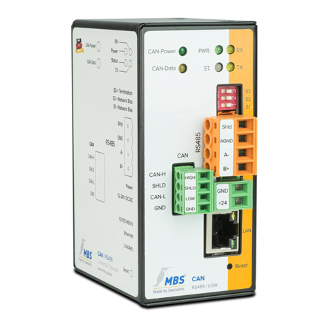
MBS maxi Mk II User manual

MANUAL
maxi | Mk II
Dated 2020/01

MBS UGW maxi | Mk II Contents 2 of 54
Table of contents
1Introduction..............................................................3
2Safety.........................................................................6
3Classification and purpose...................................8
4Specifications and connected loads..................9
5Installation ............................................................... 11
6Connections and operating controls ............... 13
7Configuration......................................................... 14
8User interface, operation and functions ......... 16
9Product support ................................................... 53
10 Conformity............................................................. 54

MBS UGW maxi | Mk II Introduction 3 of 54
1Introduction
Safety information is shown as follows in this manual:
Danger
Failure to observe this safety information will result in death or
serious injury to persons.
Warning
Failure to observe this safety information may result in death or
serious injury to persons.
Caution
Failure to observe this safety information may result in minor to
moderate injury to persons.
Notice
Information on avoiding damage to the device or on the correct use
of components and documents.
Notation and symbols used
Notice
The following notation and symbols are used in this manual.
<Buttons>
The notation <Button> is used for
buttons that must be mentioned in
the running text.
Graphic symbols are also used for
buttons where suitable.
Network commands as well as
file and product names
Network commands, such as
traceroute or ping, are written in
italics. The same applies to file and
product names.

MBS UGW maxi | Mk II Introduction 4 of 54
Copyright protection This document is protected by copyright. Reproduction, reprinting,
even of extracts, as well as reproduction of the images, even in a
modified state, is only permitted with the written consent of the
manufacturer.
Warranty This manual must be read carefully before installing and
commissioning the device. The warranty entitlement lapses if the
device is installed by untrained personnel. Harm caused by
disregarding the allowable connected loads and ambient conditions or
by using unsuitable tools is also excluded.
Limitation of liability All information and notes in this manual were compiled taking the
applicable standards and regulations, best engineering practice and
the manufacturer's extensive knowledge and experience into
consideration.
The manufacturer assumes no liability for indirect and direct damage
due to:
•Ignorance of this manual
•Improper use
•Use of untrained personnel
•Damage due to incorrect installation
•Unauthorised modifications to the hardware and software
•Use of non-approved components
The obligations agreed in the delivery contract, the general terms and
conditions as well as the manufacturer's delivery conditions and the
legal regulations applicable at the time of the conclusion of the
contract apply.

MBS UGW maxi | Mk II Introduction 5 of 54
Target group This manual is intended for specialist personnel who are familiar with
the configuration of gateways in building automation.
Intended use
The gateway is only intended for coupling networks in building
automation with the connected loads stipulated in the specifications.
Notice
This manual is part of the product and must remain with the end
customer.

MBS UGW maxi | Mk II Safety 6 of 54
2Safety
General The hardware and software present no direct hazards. However, in
their function as a gateway between networks in building
infrastructures, they are able to seriously disrupt the interaction of
network components.
Warning
Misconfiguration of hardware and software!
Faulty configuration of hardware and software can cause
malfunctions in the building infrastructure on network components,
sensors or actuators, for example:
•Monitoring devices, such as fire alarm or intrusion detection
systems, are deactivated.
•Machines and fans start up unexpectedly.
•Gate valves and other valves open or close unintentionally.
Under certain circumstances, this can lead to serious injuries or
death.
The gateway should only be configured by specialist personnel
who are familiar with network configuration!

MBS UGW maxi | Mk II Safety 7 of 54
Warning
Electric shock hazard!
When installing and connecting the device, live parts of the overall
system in the control cabinet or other system parts may come into
contact.
Under certain circumstances, this can lead to serious injuries or
death.
Electrical devices may only be installed and connected by qualified
electricians.

MBS UGW maxi | Mk II Classification and purpose 8 of 54
3Classification and purpose
Classification The devices of the UGW (Universal Gateway) product family, with their
different interfaces, serve as gateways between different networks.
Purpose The universal gateway (UGW) maxi | Mk II offers 20,000 data points in
the basic version and 40,000 data points in the extended version. It
therefore reduces the number of hardware components in a control
cabinet. It also requires less space, wiring and electricity.
Manufacturer-specific communication protocols can be added if
required.
Typical maxi | Mk II universal gateway deployment scenario
1 Ethernet BACnet/IP
2 PC with projecting
software or building
control system
3 RS485 (two-wire network)
4 DDC automation station
5 MBS universal gateway
6 DDC automation station
7 Field device, e.g. pump

MBS UGW maxi | Mk II Specifications and connected loads 9 of 54
4Specifications and connected loads
Casing Metal casing for top-hat rail mounting
Assembly DIN top-hat rail TS35
in accordance with EN 60715
Weight 448 gram
H/W/D dimensions
in millimetres
141/30/99
(104 including DIN top-hat rail adapter)
Lateral spacing to other
devices ≥ 15 mm
Ambient temperature 0–45 °C, 32–113 °F
Ambient humidity 20–80 percent relative humidity,
non-condensing
Power supply +12 V to +24 V DC +/- 15% (PELV),
LED to indicate the power supply
Power consumption 5 watts
RS485 | COM1 RS485 interface
4-pin Weidmüller connector
with the connectors:
SGND (signal ground)
A- inverted wire
B+ non-inverted wire
LED TX and RX to display sending and
receiving data

MBS UGW maxi | Mk II Specifications and connected loads 10 of 54
RS232 | COM2 RS232 interface
4-pin Weidmüller connector
with the connectors:
SGND (signal ground)
RXD send data
TXD receive data
LED TX and RX to display sending and
receiving data
LAN1 RJ45 10/100/1000 MBit Ethernet
Link indicates a LAN connection
10/100 indicates the connection speed
LAN2 RJ45 10/100/1000 MBit Ethernet
Link indicates a LAN connection
10/100 indicates the connection speed
Number of possible data
point connections
20,000 (article number 11-0033)
expansion to 40,000
(article number 13-0007)

MBS UGW maxi | Mk II Installation 11 of 54
5Installation
Warning
Electric shock injury hazard!
The device may only be installed in a control cabinet (top-hat rail)
when the power is disconnected.
The system must be disconnected for installation.
The gateway is exclusively operated with a supply voltage of 12 V to
24 V direct voltage (protective extra low voltage).
Warning
Electric shock injury hazard and damage to device!
Connecting the device to deviating, excessively high supply
voltages may lead to serious injuries or death.
No supply voltages that deviate from the connection values
specified in the technical data may be used.

MBS UGW maxi | Mk II Installation 12 of 54
Warning
Electric shock injury hazard and damage to device!
Operating the device with connection cables that are not suitable
for the permissible ambient temperature range, can damage these
cables. This may lead to serious injuries or death.
Only connection cables suitable for the ambient temperature range
specified in the technical data may be used.
Notice
A sufficient distance (≥ 15 mm) to the other components on the
top-hat rail is recommended for mounting the device in the control
cabinet.
This ensures better heat dissipation, which can have a positive
influence on the service life of the device.
The connecting cables used must be suitable for the ambient
temperature range specified in the technical data.

MBS UGW maxi | Mk II Connections and operating controls 13 of 54
6Connections and operating controls
1 DIP switches
S1 bias voltage
for RS485 interface
S2 bias voltage
for RS485 interface
S3 120 Ohm
termination impedance
(termination)
2 RS485
SGND signal ground
A- inverted wire (RX LED yellow)
B+ non-inverted wire (TX LED yellow)
3 RS232
SGND signal ground
RXD send data (RX LED yellow)
TXD receive data (TX LED yellow)
4 USB
USB 2.0, max. 500 mA
5 Reset
DIP switch
6 Status
LED
7 LAN 2
RJ45 10/100/1000 MBit Ethernet
8 LAN 1
RJ45 10/100/1000 MBit Ethernet
9 Power supply
GND, ground
+24 volt supply voltage (PELV)
10 PWR
LED (green)
1
4
9
7
2
3
6
8
10
5

MBS UGW maxi | Mk II Configuration 14 of 54
7Configuration
Web server The gateway has an integrated web server for configuration. The web
server provides the configuration settings in the form of websites. The
web interface is used, for example, to configure the IP and other
settings. All changes must be saved by clicking <Save>. Following
changes to the network configuration, it is sometimes necessary to
restart the gateway.
Notice
In order to follow this manual, the web server language must be set
to English by clicking the symbol.
Under factory settings, the web server is accessible at the following IP
address:
IP address under factory settings: 169.254.0.1
Subnet mask 255.255.0.0
Username gw
Password
(under factory settings) GATEWAY
Connect the MBS UGW to your PC with the network cable for
configuration.
Notice
The computer’s LAN connection must be configured correctly. To
set the network address manually, define the IP address as
169.254.0.2, for example. The subnet mask must match that of the
gateway.

MBS UGW maxi | Mk II Configuration 15 of 54
Enter the IP address of the UGW web server in a web browser:
http:// 169.254.0.1.
Notice
The “REFRESH” symbol must always be used to update the screen
in the web server.
Using the web browser’s standard refresh button will log you out of
the web server.
Certain configurations require the device to be restarted. This is
indicated in this manual with <Restart required>. The web server
will show at the upper edge of this button.
Web server language The gateway provides the websites in both German and English.
Switch the language in the web interface using the respective flag
symbols in the top right.
Logging on You must enter your username and pre-set password to log on to the
web server. The password can be changed on the configuration pages
(Menu item General > Password).

MBS UGW maxi | Mk II User interface, operation and functions 16 of 54
8User interface, operation and functions
When you have successfully logged in, you will see the MBS Gateway
configuration interface with an overview page. The upper menu bar is
there for you to navigate this.
Upper menu The web interface contains the following menus for configuring the
gateway:
•General
•UGW communication driver
•MODBUS Master
•BACnet
•Help
The menu items General, Help and UGW are always available. The
other menu items are determined by the universal gateway drivers
installed. The freely-selectable MBS Gateway name is also displayed
above the menu bar. All MBS Gateway settings and functions can be
found in the General menu. These are independent of the drivers
installed. Documents and diagnosis functions can be accessed via the
Help menu.
The username of the current user is shown in the top right. The
meanings of the symbols are as follows:
Log out of user interface
Change language

MBS UGW maxi | Mk II User interface, operation and functions 17 of 54
Left-hand lower menu Each menu has submenus, shown in the left-hand column, which you
use to load the individual configuration pages/screens.
8.1 General menu
General > Overview
After logging in, the universal gateway loads an overview page for the
device.
Type UGW type display
Name, installation location, description
This project-specific information serves to identify the universal
gateway. The name also appears in the upper-left part of the menu
and is displayed for you to check when backing-up data.
Status LED This describes the current status of the status LED on the front of the
universal gateway.
System start Time of last system start.
Data points Displays the number of used data points and licensed data points.

MBS UGW maxi | Mk II User interface, operation and functions 18 of 54
CPU load Displays CPU usage in %. Avoid prolonged CPU usage of over 50%.
RAM Displays the size of the used and total RAM in Mbyte. Too little free
space can lead to operational problems.
Driver Lists the current statuses of the drivers (depending on which drivers
are installed). If a driver is not online, this suggests a booting problem
or a problem with the configuration of a driver. Use the diagnostics
tool in the help menu to find out more information to solve the
problem.
General > Details
In the UGW, you can store information on the device name, the
installation location, a description of the UGW and contact partner
details. This information is used to better identify the relevant UGW in
the network when using several UGWs.
Edit the input fields (free text) and save the configuration by clicking
<Save>.

MBS UGW maxi | Mk II User interface, operation and functions 19 of 54
General > IP network
Configuring IP LAN1 (if necessary LAN2) network settings.
For the Ethernet interface(s), configure the IP address, network mask
and standard gateway (if required). The network adapter’s MAC
address is displayed.
Network name Enter a host name as well as two name servers here for name
resolution.
Services Use the drop-down list Web server access to select which protocols to
use to access the gateway in the network:
•Active port 80 with unencrypted http protocol
•Active port 443 with encrypted https protocol
•Active ports 80 and 443.
Click <Save> to apply the changed IP network settings.

MBS UGW maxi | Mk II User interface, operation and functions 20 of 54
The new IP settings are applied upon saving. It is necessary to log in
again after the IP address has been changed. If IP network services
with an IP name resolution are required, it is necessary to enter at
least one IP name server.
The secured https protocol can also be used to access the web server.
To access the web server in this way, enter “https://” before the IP
address in the web browser.
Notice
If communication protocols that operate via the network are
installed on the gateway, you need to carry out a system restart.
This is necessary because the drivers of such protocols only apply
the settings when the system is booting up.
For the exact IP settings, you may have to contact your local
network administrator.
If the IP network is not required for gateway operation, leave the
standard settings as they are. This makes it easier to access the
gateway later.
Table of contents
Other MBS Gateway manuals
Popular Gateway manuals by other brands
Cisco
Cisco DPC user guide
Endress+Hauser
Endress+Hauser WirelessHART Fieldgate SWG70 Operating instruction

Psion Teklogix
Psion Teklogix 9150 user manual

PEMTECH
PEMTECH PT800 Series Operator's manual

EuroTech Communication
EuroTech Communication GSM gateway user manual
Westell
Westell VersaLink 7550 user guide
