MC Technologies MC-MRL User manual

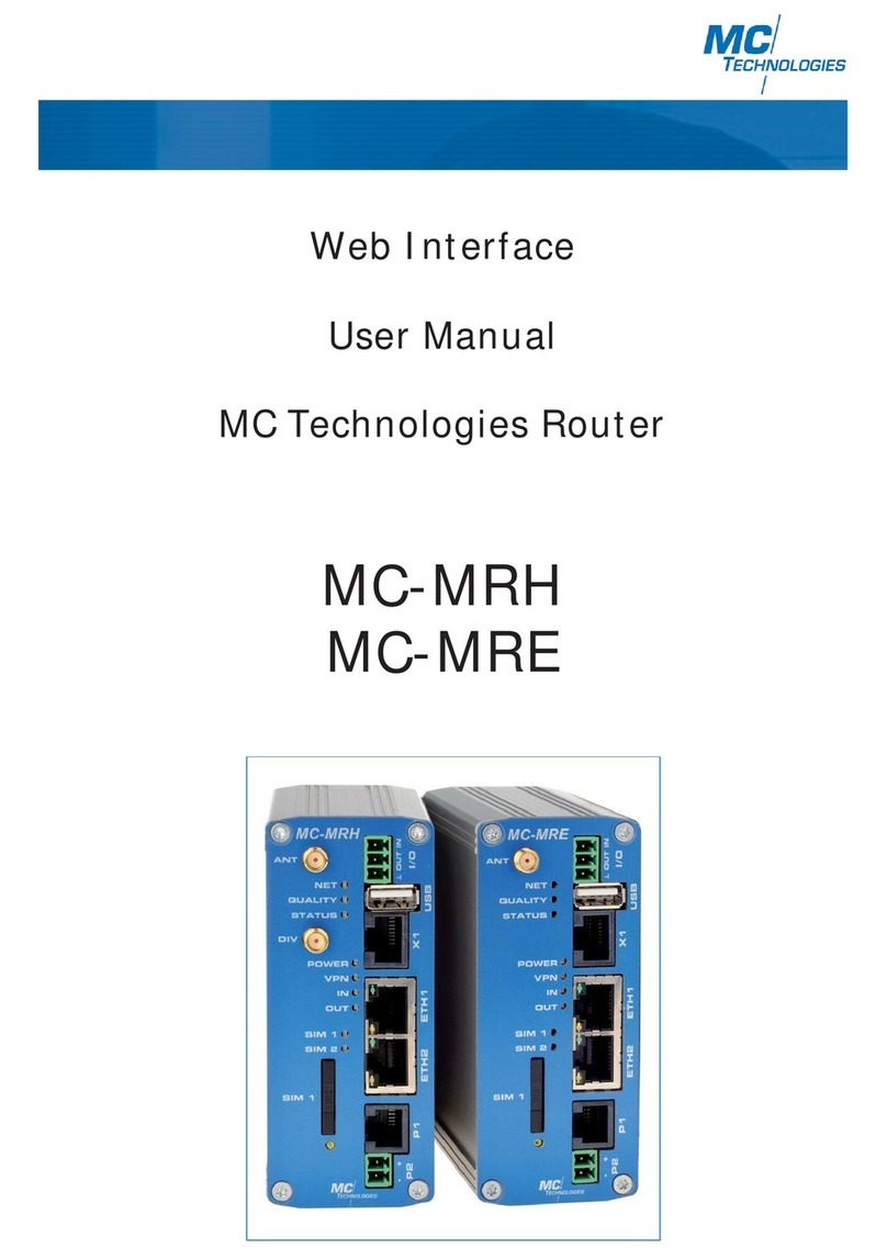
User Manual
Web Interface
MC Technologies Router
MC-MRL/MC-MRL-4
MC-MRH/MC-MRH-4
MC-MRE/MC-MRE-4

Router Description
Mobile radio routers were designed for industrial use.
They allow switching as needed between mobile radio routers with high and medium bandwidth.
Advantages at a glance:
• Easy expansion of protected networks.
• High-security data transfer via IPsec or OpenVPN tunnel, plus integrated firewall.
• Easy and identical configuration of router family via integrated web server, USB stick
or "remote".
• Compatible with mobile networks world-wide - can be used internationally.
• Event alerts by SMS and email.
• Top-hat rail mounting.
• Integrated logbook records device-specific events.
• Use of applications with RS232, RS485 or M-Bus interfaces on demand
(only MC-MRL/MC-MRH/MC-MRE)
• Use of integrated GPS receiver for positioning on demand (only MC-MRH/MC-MRH-4).
• Delivered ready-to-use, including power supply plug, Ethernet connecting cable and
mobile radio antenna.
• SIM cards are not included in the standard scope of delivery.
2MC Technologies Router program

Contents
1. Configuration via the integrated web interface 5
1.1 Preparations 5
1.2 Configuration 1.2.1 Configuration via web interface 5
1.2.2 Local IP address is not (longer) known - configuration button 5
1.2.3 Resetting all parameters 5
1.3 Status 1.3.1 Radio 6
1.3.2 Network Connections 7
1.3.3 I/O Status 8
1.3.4 ComSERVER (Only for MC Router with RS232 or RS485 interface on X1) 8
1.3.5 Routing Table 8
1.3.6 DHCP Leases 9
1.4 Local Network 1.4.1 IP Configuration 9
1.4.2 DHCP Server 10
1.4.3 Local Static Routes 11
1.5 Wireless Network 1.5.1 Radio Set-up 12
1.5.2 SIM (SIM1) 13
1.5.3 Backup SIM (SIM2) 14
1.5.4 SMS Configuration 14-15
1.5.5 Packet Data Set-up 16
1.5.6 Wireless Static Routes 17
1.5.7 DynDNS 18
1.5.8 Connection Check 18
1.6 Network Security 1.6.1 General Set-up (Firmware 1.xx.x) 19-20
1.6.1 General Set-up (Firmware 2.xx.x) 20
1.6.2 Firewall 21
1.6.3 NAT Table (Port forwarding) 22
1.7 VPN 1.7.1 IPsec 1.7.1.1 Connections 23-25
1.7.1.2 Certificates 26-27
1.7.1.3 Status 27
1.7.2 OpenVPN 1.7.2.1 Connections 28-30
1.7.2.2 Port Forwarding 31
1.7.2.3 Certificates 31-32
1.7.2.4 Static Keys (Preshared Key) 32
1.7.2.5 Status 32
1.8 I/O 1.8.1 Inputs 33
1.8.2 Outputs 33-34
1.8.3 Phonebook 34
1.8.4 Socket Server 34
1.9 System 1.9.1 Hardware 35
1.9.2 Software 36
1.9.3 System Configuration 36-38
1.9.4 User 39
1.9.5 Log File 39
1.9.6 ComSERVER (Only for MC Router with RS232 or RS485 interface on X1) 40
1.9.7 SMTP configuration 40-41
1.9.8 SMTP configuration - sending emails 41
1.9.9 Configuration Up-/Download 42
1.9.10 RTC - Setting the time and date / Time Server 43
1.9.11 Reboot - restarting the router 44
1.9.12 Firmware Update 44
3
User Manual Web Interface MC-MRL/MC-MRL-4/MC-MRH/MC-MRH-4/MC-MRE/MC-MRE-4 - 05/2015

4MC Technologies Router program
2. Additional functions 2.1 Router configuration using SSH and XML file 45
2.1.1 Download configuration via SSH 45
2.1.2 Upload configuration via SSH 45
2.2 Sending and receiving IO status, email, SMS and router status using XML
files via the router socket server 46
2.2.1 Sample XML files 46
2.2.2 Functions test using Windows HyperTerminal 47
2.3 Using the integrated GPS receiver in the MC-MRH router 48
2.3.1 Activating the GPS function 48
2.3.2 Displaying the GPS coordinates in the web interface 49
2.3.3 Receiving the GPS coordinates as an SMS 49
2.3.4 GPS coordinates as an XML file 49

1. 1. Configuration via the integrated web interface
1.1 Preparations
1. Hook the router up to the power supply using connection "P1" , "P2" or "POW".
2. To configure, connect the PC and the router to Ethernet port “ETH1“ using an Ethernet cable.
3. For configuration, you will need a browser (i.e. Mozilla Firefox, Microsoft Internet Explorer, etc.) on a PC.
The router must be connected to the power supply. The PC to be used for configuration must be connected to an Ethernet
port on the router.
1.2 Configuration
1.2.1 Configuration via web interface
1. The PC must be set to "obtain IP address automatically".
This is the default setting for PCs.
2. Open a browser on the PC.
3. Type the IP address (default: 192.168.0.1) in the address field.
4. For authentication purposes a user name and password must be entered. The default settings for the user name
and password are both "admin", which should be entered in the corresponding fields. For your security, the
password setting can be changed at any time using the "System/User" menu item on the web interface
(see Page 39).
5
User Manual Web Interface MC-MRL/MC-MRL-4/MC-MRH/MC-MRH-4/MC-MRE/MC-MRE-4 - 05/2015
1.2.2 Local IP address is not (longer) known – configuration button
The router is set to "Web access reset" unless you change the default setting. Press the configuration button for at
least 5 seconds using a pointed object. The router web interface can be temporarily readdressed using the default IP
address (192.168.0.1) for the Ethernet (LAN) connection. The configuration settings will not be lost when doing so.
Web access reset
Important note! The router does not supply any IP address to the connected PC via DHCP. You must thus
assign a fixed IP address to the PC (e.g. 192.168.0.2, default gateway 192.168.0.1).
You will now have access to web management using the default access data. Please check the settings for the router IP
address, user name and password and make any changes required.
Factory reset
You changed the setting to "Factory reset" (see Item 1.9.3 "System Configuration/Reset button"). Press the configura-
tion button for at least 5 seconds using a pointed object. The router web interface can be readdressed using the
default IP address (192.168.0.1) for the Ethernet (LAN) connection.
Important note! All configuration settings will be deleted and reset to the "Factory Defaults" setting.
1.2.3 Resetting all parameters on the web interface
Resetting of all router settings to the factory default mode can be carried out via the internal web interface. Please
click on the "Apply" button for the "Reset to Factory Defaults" function in the "System/Configuration Up-/Download"
sub-menu.
To reconfigure the router using the default IP address you will need to use the configuration button on the rear side of
the device. This function depends on the setting you defined in Section 1.9.3 "Reset button".

6MC Technologies Router program
1.3 Status
Display basic status information.
1.3.1 Radio
Display mobile connection.
Radio Status
Provider Name of mobile service provider.
Networkstatus Status in cellular network.
Registered home: Registered in the cellular network.
Roaming: Registered in a third-party cellular network.
Waiting for PIN: Waiting for PIN to be entered.
Waiting for PUK: Locked SIM card must be unlocked with PUK.
Wrong PIN: Wrong PIN configured in the router.
No SIM Card: Put SIM card in.
Power off: The GSM module is still off.
Signal level Display receive level.
Packet data Offline: No packet data connection.
GPRS online: Active GPRS connection.
EDGE online: Active EDGE connection.
UMTS online: Active UMTS connection.
HSDPA/HSUPA online: Active HSDPA/HSUPA connection.
LTE online: Active LTE connection.
SIM #1 IMSI Specification of IMSI (International Mobile Subscriber Identity) by the SIM card.
Local area code Number in cellular network via current location.
Cell ID Clear recognition of a GSM cell in the cellular network.

Network Connections
Wireless Network
Link TCP/IP connected: Active GPRS/EDGE/UMTS/HSPA or LTE packet data connection in cellular network.
VPN connected: Active VPN connection via the cellular network.
Not connected: No packet data connection in the cellular network.
IP Address Allocated IP address from the cellular network.
Netmask Allocated net mask from the cellular network.
DNS Server IP address of the DNS server.
Sec. DNS Server IP address of the alternate DNS server.
Expires Only MC-MRL (LTE) remainder duration until prompt for a new IP address.
RX bytes Sum of received data since last login to cellular network.
TX bytes Sum of sent data since last login to cellular network.
Local Network
Link Connected: The local Ethernet is active.
Not connected: The local Ethernet is not active.
IP Address Router IP address in the local network.
Netmask Router net mask in the local network.
Status information on mobile connection and on local Ethernet network.
1.3.2 Network Connections
7
User Manual Web Interface MC-MRL/MC-MRL-4/MC-MRH/MC-MRH-4/MC-MRE/MC-MRE-4 - 05/2015

8MC Technologies Router program
Status information of I/O interfaces IN and OUT.
1.3.3 I/O Status
Input Signal Event
#1 Low: The signal is low. None: No event has been triggered.
High: The signal is high. SMS: An SMS is being sent.
E-Mail: An email is being sent.
Output Signal Event
#1 ON: Output active. Based on: Manual ON, Remote Controlled ON, Radio Net
work ON, Packet Service ON, VPN Service ON, Incoming Call
ON or Connection lost ON.
Off: Output is not active.
Display of current routing table.
1.3.5 Routing Table
Status display of integrated ComSERVER
1.3.4 ComSERVER (only for MC Router with RS232 or RS485 interface on X1)
See also 1.9.6. ComSERVER

1.4 Local Network
Setup of local IP address and subnet mask for router. Set your parameters and click "Apply". Your parameters have
been saved but not yet applied. To apply the setup, restart the router.
1.4.1 IP Configuration
IP Configuration
Current Address
IP Address Current local IP address of the router. If you forget the IP address and would like to configure the
router, follow the instructions under 1.2 "Configuration" on Page 5.
Subnet Mask Current subnet mask.
Type of IP address Static (default): The IP address has been set.
assignment DHCP: The IP address and the subnet mask are obtained dynamically from a connected
DHCP server.
Alias Addresses
IP Adress Alias addresses how the router can be reached alternatively (up to eight other IP addresses).
Subnet Mask Click "New" and add the other IP addresses, as well as the corresponding subnet masks.
Display allocation of MAC address to IP address of terminal equipment connected to the local Ethernet.
Connected terminal devices with a fixed IP address will not be shown.
1.3.6 DHCP Leases
9
User Manual Web Interface MC-MRL/MC-MRL-4/MC-MRH/MC-MRH-4/MC-MRE/MC-MRE-4 - 05/2015

10 MC Technologies Router program
An IP address can be allocated automatically to local equipment connected via Ethernet using DHCP (Dynamic Host
Configuration Protocol).
1.4.2 DHCP Server
DHCP Server
DHCP Server Disabled/Enabled: Click "Enabled" if the router should allocate the IP addresses to the connected
terminal equipment as the DHCP server at start-up.
Domain Name Domain name to be broadcast via DHCP.
Lease Time (d,h,m,s) Validity period of allocated network configuration.
Dyn. IP address Disabled/Enabled: Click "Enabled" if an IP address should be dynamically allocated to the connected
terminal equipment in a set range.
Begin IP Range Starting address for the address range from which IP addresses should be distributed.
End IP Range Ending address for the address range from which IP addresses should be distributed.
Static IP address Static allocation of the IP address using the MAC address.
allocation
Client MAC address MAC address of the terminal equipment.
Client IP address IP address of the terminal equipment. Static allocation of the IP addresses should not overlap with the
dynamic IP addresses. An identical IP address should not be used in multiple static allocations.

Data packets from the local network can be defined by static routes using other gateways for alternative routes.
1.4.3 Local Static Routes
Local Static Routes
Network Network in CIDR notation: IP address / Net mask
Example: xxx.xxx.xxx.xxx/yy (x..=IP address; yy=net mask)
Example: yy=24 (number of binary "ones") => net mask = 255.255.255.0
Gateway The gateway how this network can be reached.
11
User Manual Web Interface MC-MRL/MC-MRL-4/MC-MRH/MC-MRH-4/MC-MRE/MC-MRE-4 - 05/2015

MC Technologies Router program
12
1.5 Wireless Network
Set-up for using the cellular network.
1.5.1 Radio Set-up
Radio Set-up
Frequency Set-up of the frequency range of the cellular network in which the router should work.
UMTS Freq. Set-up of the UMTS frequency range of the cellular network in which the router should work.
UMTS off: Deactivate UMTS and HSPA.
Backup SIM (SIM2) Disabled: The back-up SIM (SIM2) is inactive.
Enabled: Back-up SIM active if a connection to the provider of the standard SIM (SIM1) for the set
"provider timeout" period fails. The duration of the back-up SIM (SIM2) is determined by
setting the "back-up runtime". After this period the standard SIM is reactivated.
Always: Only the back-up SIM (SIM2) is active.
Input 1: Switch to back-up SIM (SIM2) if input 1 high is on level.
Provider Timeout Amount of time in minutes after which the back-up SIM card (SIM2) should be switched to if the primary
cellular network (SIM1) is down.
Backup Runtime Amount of time in hours after which the primary cellular network (SIM1) should be switched back on.
Daily relogin Disabled: Deactivate daily login.
Enabled: Activate daily login. Daily login first attempts to log onto
primary cellular network (SIM1).
Time Time of day at which the router independently logs out of the cellular network and logs back in.
Relogin first attempts to log onto primary cellular network (SIM1).

User Manual Web Interface MC-MRL/MC-MRL-4/MC-MRH/MC-MRH-4/MC-MRE/MC-MRE-4 - 05/2015 13
SIM (SIM1)
Country Preselection of the country in which the router should operate. Under the menu option „Provider“, you
can then select the mobile service provider of the selected country.
PIN PIN entry for SIM card SIM1.
Roaming Set-up for use of third-party cellular networks.
Enabled: The router can log onto third-party networks. The "Auto" setting selects the provider with
the strongest signal. This may result in additional cost, depending on the mobile service
contract. Alternatively, you can choose a provider yourself.
Disabled: Roaming is deactivated and only the local network of the provider is used. If this network
is not available, the router cannot connect to the Internet.
Provider Selection of the provider via which the router connects to the Internet. The selection changes
according to the country selected under "Country" in the menu.
Auto: The router selects the provider automatically.
Username User name for access.
Password Password for access.
The user name and the password are given to you by your mobile service provider. Do not leave the
user name and password blank during configuration, even if the mobile service provider does
not require any specific input!
APN The APN is given to you by your mobile service provider. APN: (Access Point Name) is the name of the
access point in the mobile service provider's packet data network.
Authentication The default setting is "All protocols". Some providers require a specific authentication setting
(refuse MSCHAP, CHAP only, PAP only) here. Consult your provider if necessary.
Settings for the primary mobile connection via SIM1.
1.5.2 SIM (SIM1)

14 MC Technologies Router program
Settings for the back-up mobile connection via SIM2.
1.5.3 Back-up SIM (SIM2)
Back-up SIM (SIM2)
The same settings apply here as for Item 1.5.2 SIM (SIM1) (see Page 13).
The second SIM card (SIM2) is located inside the router housing. To insert or remove the
SIM2 card, remove the back panel of the router.
1.5.4 SMS Configuration
Controlling the mobile router by SMS
Under "SMS Control", click Enabled. Define an SMS password for security.
The password can comprise up to 7 alphanumeric characters.
SMS Syntax
Commands are inputs using the following SMS syntax:
#<password>:<command>
<password> = ('A'-'Z', '0'-'9') // Up to 7 alphanumeric characters
<command> = SET:<sub_cmd> // Set command (ON)
<command> = CLR:<sub_cmd> // Clear command (OFF)
<sub_cmd> = OUTPUT // Output set to ON/OFF
<sub_cmd> = IPSEC // IPsec VPN 1 ON/OFF
<sub_cmd> = IPSEC:n // IPsec VPN n ON/OFF, n={1..x}
<command> = SEND:STATUS // Send a status SMS to the caller
<command> = RESET // Reset all alarms
<command> = REBOOT // Router reboot
Example:
Turn on the I/O interface output. The (example) password is: "pw1212".
The SMS sent to the router's call number should then have the following content: #pw1212:SET:OUTPUT.

SMS Configuration
SMS control Disabled: Remote control of router by SMS not possible.
Enabled: Remote control of router by SMS activated.
SMS Password SMS password for remote control.
SMS forward Disabled: Forwarding of SMS message via Ethernet not possible.
Enabled: Forwarding of SMS message via Ethernet activated.
Server IP address IP address to which the SMS message should be forwarded.
Server Port (default 1432) Port to which the SMS message should be forwarded.
Forwarding an SMS to a socket server
The router can forward received SMS messages to a terminal device through the Ethernet interface. A socket server
must be installed on the terminal device to receive XML files.
Under "SMS forward", click Enabled. Enter the recipient's IP address and the port of the terminal device you want to
talk to. The default value for the server is Port 1432. The received SMS is forwarded in the following example format:
Important note!
The call number should be included as an entry in the phonebook (see Page 34) in order for the router to identify it.
Example:
<?xml version="1.0"?>
<cmgr origaddr="+49172123456789" timestamp="10/05/21,11:27:14+08">
SMS message</cmgr>
origaddr = Sender's call number
timestamp = Time-stamp of the Service Centre in GSM 03.40 format
15
User Manual Web Interface MC-MRL/MC-MRL-4/MC-MRH/MC-MRH-4/MC-MRE/MC-MRE-4 - 05/2015

16 MC Technologies Router program
1.5.5 Packet Data Set-up
Activation and deactivation of the packet data connection via GPRS, EDGE, UMTS, HSPA or LTE.
Packet Data Set-up
Packet data Disabled: Access to GPRS/EDGE/UMTS/HSPA or LTE deactivated.
Enabled: Allow access to GPRS/EDGE/UMTS/HSPA or LTE.
Debug Mode Disabled: Detailed information on packet data connection not saved in the log file.
Enabled: Detailed information on packet data connection saved in the log file.
Allow Compression Disabled: Data compression of the packet data connection is deactivated.
Enabled: Data compression of the packet data connection is activated (default).
MTU (default 1500) Maximum packet size in bytes in the packet data network.
Event Definition of packet data connection start.
Initiate: Automatic start.
Initiate on Input #1: Start controlled through IN signal in the I/O interface.
Manual DNS Disabled: Automatic DNS set-up. The DNS settings of the provider will be used.
Enabled: Manual DNS set-up.
DNS Server IP address of the primary DNS server in the mobile service network.
Sec. DNS Server IP address of the alternate DNS server in the mobile service network.

1.5.6 Wireless Static Routes
Data packets from the local network can be defined using static routes for alternative routes in the mobile service
network.
Wireless Static Routes
Network Network in CIDR notation.
Gateway The gateway via which this network can be reached.
17
User Manual Web Interface MC-MRL/MC-MRL-4/MC-MRH/MC-MRH-4/MC-MRE/MC-MRE-4 - 05/2015

For continuous connection monitoring, use "Connection Check" to check for a packet data connection in the mobile
service network. If the connection is lost, an action can be configured for establishing a new connection.
Note: Please note that frequent connection checks can lead to increased data traffic and corresponding costs.
1.5.8 Connection Check
18 MC Technologies Router program
The router IP address in the cellular network/Internet is allocated dynamically by the mobile service operator. A name
can be allocated to the dynamic IP address using a DynDNS provider, via which the router can then be reached over
the Internet. The DynDNS Client must be saved and activated in the router accordingly.
Note: For this to work, the provider must have allocated a public IP address to the router, not a private one.
This is not the case with all providers. DynDNS cannot replace a static IP address and has limited reliability.
1.5.7 DynDNS
DynDNS Set-up
Status Disabled: Deactivate DynDNS client.
Enabled: Activate DynDNS client.
DynDNS Provider Select the name of the provider with whom you are registered,
i.e. DynDNS.org, TZO.com, dhs.org., selfHost.de, custom DynDNS.
Use the "custom DynDNS" setting to select your preferred DynDNS provider.
Please also enter the provider’s server address under "DynDNS Server".
DynDNS Username Enter the username for your DynDNS account here.
DynDNS Password Enter the password for your DynDNS account here.
DynDNS Hostname The host name selected for this router for DynDNS service.
Your router can then be reached under this host name.

Connection Check
Status Disabled: Connection check is deactivated (default).
Enabled: Connection check is activated.
Host #1 ... #3 IP address or host name of the reference point for the connection check.
"Local" option, when dealing with an address which can be reached via a VPN tunnel.
Check every Check interval in minutes.
Max. retry Number of repetitions until the configured action "Activity" is performed.
Activity Reboot: Restart the router.
Reconnect: Re-establish packet data connection.
Relogin: Restart the cellular interface by redialing the mobile service network.
None: None.
19
User Manual Web Interface MC-MRL/MC-MRL-4/MC-MRH/MC-MRH-4/MC-MRE/MC-MRE-4 - 05/2015
1.6 Network Security
These settings apply for routers with 1.xx.x firmware (see Release Version under "System/Hardware").
Important note! Routers with Release 1.xx.x firmware cannot be updated to Version 2.xx.x.
Please contact the manufacturer.
1.6.1 General Set-up (Firmware 1.xx.x)

20 MC Technologies Router program
These settings apply for routers with 2.xx.x firmware (see Release Version under "System/Hardware").
Important note! Routers with Release 1.xx.x firmware cannot be updated to Version 2.xx.x.
Please contact the manufacturer.
1.6.2 General Setup (Firmware 2.xx.x)
General Set-up
Firewall Disabled: The integrated firewall is deactivated, no filtering of data packets.
Enabled: The integrated firewall is activated (default).
Port forwarding Disabled: Port forwarding via NAT table is blocked.
via NAT table Enabled: Port forwarding via NAT table is allowed.
Block outgoing Netbios Disabled: Outgoing NetBIOS requests are allowed.
Enabled: Outgoing NetBIOS requests are blocked (default).
Ping (ICMP) external Disabled: A ping request from the external IP network to the router is ignored (default).
Enabled: A ping request from the external IP network to the router is returned.
Web based Management Disabled: External configuration via the web interface is not possible (default).
external Enabled: External configuration via the web interface is possible.
NAT (Masquerade) Disabled: No IP masquerading performed.
external Enabled: IP masquerading is activated. Communication from a private, local network
to the Internet is allowed (default).
Device access via SSH Disabled: Local SSH access to the router is not possible (default).
Enabled: Local SSH access to the router is possible.
External access via SSH Disabled: Remote SSH access to the router is not possible (default).
Enabled: Remote SSH access to the router is possible.
General Set-up
Firewall Disabled: The integrated firewall is deactivated, no filtering of data packets.
Enabled: The integrated firewall is activated (default).
Port forwarding Disabled: Port forwarding via NAT table is blocked.
via NAT table Enabled: Port forwarding via NAT table is allowed.
Block outgoing Netbios Disabled: Outgoing NetBIOS requests are allowed.
Enabled: Outgoing NetBIOS requests are blocked (default).
Ping (ICMP) external Disabled: A ping request from the external IP network to the router is ignored (default).
Enabled: A ping request from the external IP network to the router is returned.
External SNMP access Disabled: Remote SNMP Access is not possible.
Enabled: Remote SNMP Access is possible.
External Web based Disabled: External configuration via the web interface is not possible (default).
Management via HTTP Enabled: External configuration via the web interface is possible.
NAT (Masquerade) Disabled: No IP masquerading performed.
external Enabled: IP masquerading is activated. Communication from a private, local network
to the Internet is allowed (default).
Device access via SSH Disabled: Local configuration via the web interface and https is not possible (default).
Enabled: Local configuration via the web interface and https is possible.
External access via SSH Disabled: External configuration via the web interface and https is not possible (default).
Enabled: Configuration via the web interface and https is possible.
This manual suits for next models
5
Table of contents
Other MC Technologies Network Router manuals