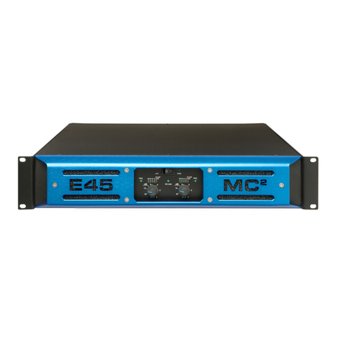
MC2 Audio E45 User manual

E45
E45E45
E45
OWNER’S
MANUAL
(BG version)
(BG version)(BG version)
(BG version)
MC
2
AUDIO Ltd.,
Units 6-8, Kingsgate,
Heathpark Industrial state,
HONITON,
Devon X14 1YG
ngland
Tel: ++(0)1404.44633 Fax: ++(0)1404.44660
www.mc2-audio.co.uk

2
CONTENTS
EC DECLARATION OF CONFORMITY 3
IMPORTANT SAFETY INSTRUCTIONS 4, 5, 6, 7
INSTALLATION Electrical 4
RF Emi ion 8
Mechanical 8
GENERAL INFORMATION 9
CONNECTIONS Input 10
Output 10
Bridged Operation 11
OPERATION Switching on 11
Level control 11
Bar ignal indicator 11
-3dB indicator 11
Limiter 11
PRC indicator 11
Temperature control 12
Fault indicator 12
Bridged LED 12
MAINTENANCE 12
TECHNICAL SPECIFICATION 13
APPENDIX Table of PRC etting 14

3

4
Important Safety Instructions
1) Read the e in truction .
2) Keep the e in truction .
3) Heed all warning .
4) Follow all in truction .
5) Do not block any ventilation opening , in tall in accordance with the manufacturer’
in truction .
6) Unplug thi apparatu during lightning torm or when unu ed for long period of time.
7) Clean only with a dry cloth.
8) Do not u e thi apparatu near water; the apparatu hall not be expo ed to dripping or
pla hing and no object filled with liquid , uch a va e hall be placed on the
apparatu .
9) Refer all ervicing to qualified ervice per onnel. Servicing i required when the
apparatu ha been damaged in any way, uch a if the power- upply cord or plug i
damaged, liquid ha been pilled or object have fallen into the apparatu , the
apparatu ha been expo ed to rain or moi ture, doe not operate normally, or ha
been dropped.
Installation Instructions: ELECTRICAL
The amplifier ha been manufactured to comply with your local power upply requirement , but before
connecting the unit to the upply, en ure that the voltage (printed on the rear panel) i correct.
Make ure power outlet conform to the power requirement li ted on the back of the unit. Damage
cau ed by connecting to improper AC voltage i not covered by the warranty.
SA ETY WARNING
Where a MAINS plug or appliance coupler i u ed a the di connect device, it hould remain readily
operable.
Where the amplifier i mounted in a rack and permanently connected to the main , then the rack hould
be in talled with a readily acce ible connector or an ALL POLE circuit breaker.
Thi unit i fitted with a 3-wire power cord. For afety rea on , THE EARTH LEAD SHOULD NOT BE
DISCONNECTED IN ANY CIRCUMSTANCE. If ground loop are encountered con ult the ection on
‘Input Connection ’ later in thi manual.
THE WIRING COLOURS ARE:
230V AREAS: EARTH = GREEN AND YELLOW 120V AREAS: EARTH = GREEN
NEUTRAL = BLUE NEUTRAL = WHITE
LIVE = BROWN LIVE = BLACK
WARNING To reduce the ri k of fire or electric hock, do not expo e thi apparatu to rain or
moi ture.
TO AVOID ELECTRICAL SHOCK DO NOT REMOVE COVERS. REFER ALL SERVICING TO QUALIFIED
PERSONNEL.

5
DO NOT USE THE UNIT IF THE ELECTRICAL POWER CORD IS FRAYED OR BROKEN. The power upply
cord hould be routed o that they are not likely to be walked on or pinched by item placed upon or
again t them, paying particular attention to cord and plug and the point where they exit from the
appliance.
ALWAYS OPERATE THE UNIT WITH THE AC GROUND WIRE CONNECTED TO THE ELECTRICAL SYSTEM
GROUND. Precaution hould be taken o that the mean of grounding of a piece of equipment i not
defeated.
DO NOT REMOVE THE LID. Removing the lid will expo e you to potentially dangerou voltage . There
are no u er erviceable part in ide.

6
1.
Read the e in truction .
2. Keep the e in truction .
3. Heed all warning .
4. Follow all in truction .
5. Do not u e thi apparatu near water.
6. Clean only with a dry cloth.
7. Do not block any ventilation opening , in tall in
accordance with the manufacturer’ in truction .
8. Do not in tall near any heat ource , uch a radiator ,
heat regi ter , tove or other apparatu (including
amplifier ) that produce heat.
9. Protect the power cord from being walked on or
pinched particularly at plug , convenience receptacle
and the pint where they exit from the apparatu .
10. The main circuit breaker hall remain readily
acce ible.
11. Only u e attachment /acce orie pecified by the
manufacturer.
12. U e only with the cart, tripod, bracket or table
pecified by the manufacturer, or old with the
apparatu . When a cart i u ed, u e caution when
moving the cart/apparatu combination to avoid injury
from a tip over.
13. Di connect thi apparatu during lightning torm or
when unu ed for a long period of time.
14.
Refer all ervicing to qualified ervice per onnel.
Servicing i required when the apparatu ha been
damaged in any way, uch a if the power- upply cord
or plug i damaged, liquid ha been pilled or object
have fallen into the apparatu , the apparatu ha been
expo ed to rain or moi ture, doe not operate
normally, or ha been dropped.
15. Do not expo e thi equipment to dripping or pla hing
and en ure that no object filled with liquid , uch a
va e , are placed on the equipment.
16. To completely di connect thi equipment from the AC
main , di connect the power cord from the main
circuit breaker.
17. Where the amplifier i mounted in a rack and
permanently connected to the main , then the rack
hould be in talled with a readily acce ible connector
or an ALL POLE circuit breaker with 3mm breaking
di tance .
18. Thi unit i fitted with a 3-wire power cord. For afety
rea on , THE EARTH LEAD SHOULD NOT BE
DISCONNECTED IN ANY CIRCUMSTANCE.
19. The cooling fan uck cool air in through the front and
blow hot air out at the rear of the unit through the
ventilating grill . The front and rear of the amplifier
hould have free expo ure to the air (i.e. in a rack
leave the front and rear door off), with 2cm air gap at
the ide and top. IF AIR IS NOT ALLOWED TO
ESCAPE FROM THE REAR, OVER-HEATING WILL
OCCUR. Take care when mounting other equipment in
the ame rack.
20. The main witch on the amplifier only witche one
pole of the main upply, therefore for unit with a
detachable cord to be fully di connected from the
main , the main di connect device (ie main plug or
main coupler) hould remain readily operable. For
unit with a fixed main lead the external all pole
circuit breaker with 3mm breaking di tance i the
di connect device and therefore the in tallation of the
amplifier hall be carried out in accordance with all the
applicable in tallation rule .
WARNING:
Apparatu with CLASS I con truction
hall be connected to a MAINS ocket outlet with a protective
earthing connection.
WARNING: To prevent injury, thi apparatu mu t be ecurely attached to the rack in accordance with the in tallation
in truction .

7
1. Li ez ce in truction .
2. Gardez ce in truction .
3. Faite attention à tou le averti ement .
4. Suivez toute le in truction .
5. N'utili ez pa cet appareil prè de l'eau.
6. Faite le ménage eulement avec un ti u ec.
7. Ne bloquez pa d'ouverture de ventilation, in tallez
conformément aux in truction du fabricant.
8. N'in tallez prè d'aucune ource de chaleur, comme le
radiateur , le regi tre de chaleur, le cui inière ou
d'autre appareil (en incluant de amplificateur ) qui
produi ent la chaleur.
9. Protégez la corde de pouvoir d'être marché ur ou pincé
particulièrement aux pri e de courant, le réceptacle
d'avantage et la pinte où il ortent de l'appareil.
10. Le di joncteur de conduite principale re tera an hé iter
acce ible.
11. Utili ez eulement de attachement /acce oire pécifié
par le fabricant.
12. Utili ez eulement avec le chariot, le trépied, la parenthè e
ou la table pécifiée par le fabricant, ou vendu avec
l'appareil. Quand un chariot e t utili é, utili ez la prudence
en déplaçant la combinai on de chariot/appareil pour éviter
la ble ure d'un bout.
13. Débranchez cet appareil pendant le tempête de foudre
ou quand neuf pendant un long terme de temp .
14. Renvoyez tout l'entretien au per onnel de ervice qualifié.
L'entretien e t exigé quand l'appareil a été nui de toute
façon, comme i la corde de pouvoir provi ion ou la pri e
de courant ont nui , le liquide a été déver é ou le objet
ont tombé dan l'appareil, l'appareil a été expo é pour
pleuvoir ou l'humidité, n'opère pa normalement, ou a été
bai é.
15. N'expo ez pa cet équipement au fait de tomber goutte à
goutte ou au fait d'éclabou er et garanti ez qu'aucun
objet rempli de liquide , comme le va e , n'e t placé ur
l'équipement.
16. Pour complètement débrancher cet équipement de la
conduite principale de courant alternatif, débranchez la
corde de pouvoir du di joncteur de conduite principale.
17. Où l'amplificateur e t monté dan un égouttoir et en
permanence raccordé à la conduite principale, alor
l'égouttoir devrait être in tallé avec un connecteur an
hé iter acce ible ou TOUT le di joncteur de PÔLE avec 3
millimètre ca ant de di tance .
18. Cette unité e t corre pondue avec une corde de pouvoir de
3 fil . Pour le rai on de écurité, l'AVANCE DE TERRE NE
DEVRAIT ÊTRE DÉBRANCHÉE DANS AUCUNE
CIRCONSTANCE.
19. Le ventilateur englouti ent l'air frai par le front et
oufflent l'air chaud à l'arrière de l'unité par le gril
aérant . Le front et l'arrière de l'amplificateur devraient
avoir l'expo ition libre à l'air (c'e t-à-dire dan un égouttoir
omettent le porte de devant et arrière), avec le trou
aérien de 2 centimètre aux côté et au haut. Si on NE
PERMET PAS QUE D'AIR S'ÉCHAPPE DE L'ARRIÈRE, LE
FAIT DE SURCHAUFFER SE PRODUIRA. Faite attention en
montant d'autre équipement dan le même égouttoir.
20. L'interrupteur principal ur le amplificateur ne coupe
qu'un pôle de l'alimentation ecteur. le cordon IEC
permettra de déconnecter l'appareil de l'alimentation
ecteur, pour cette rai on l'accè à ce fiche (fiche mâle
ou femelle) doit être facilité .
Pour le appareil avec un câble d'alimentation fixe an
fiche ecteur, le di po itif de coupure omnipolaire ayant
une di tance d'ouverture de contact d'au moin 3mm, era
le di po itif permettant la déconnexion complète de
l'appareil.
Pour cette rai on l'in tallation et le raccordement de
l'amplificateur devra ce faire conformément au
réglementation en vigueur.
ATTENTION
: Appareil de con truction de CLASSE I doit être ra
ccordé au ré eau électrique via une pri e de courant reliée à la
terre.
ATTENTION: Pour éviter toute ble ure, cet appareil doit être olidement fixé à la torture, conformément aux in truction
d'in tallation.

8
INSTALLATION EMC (R Emissions)
The high frequency re onant converter in the E Series amplifier have been de igned to have very
low radio frequency (RF) emi ion , which can cau e interference with other equipment. In order for thi
to be optimi ed, the amplifier hould be mounted in a metal rack enclo ure, which hould have a
eparate (technical) Earth. Alternatively a eparate earth hould be attached to the amplifier at the rear
rack mounting bracket.
INSTALLATION: MECHANICAL
To en ure that thi equipment perform to pecification, it hould be mounted in a uitable rack or
enclo ure a de cribed below. Like all high power amplifier , it hould be kept away from other
equipment which i en itive to magnetic field . Al o, thi amplifier may uffer a ub tantial reduction in
performance if it i ubjected to, or mounted clo e to equipment which radiate high RF field .
When mounting the amplifier in a rack or enclo ure, en ure that:-
1. The rear of the unit i adequately upported. The bracket which are upplied fit tandard 19 inch
(483mm) rack mounting y tem . THE FRONT PANEL IS NOT CAPABLE OF SUPPORTING THE
UNIT ON ITS OWN.
2. THERE IS ADEQUATE VENTILATION. The cooling fan uck cool air in through the front and blow
hot air out at the rear of the unit through the ventilating grill . IF THIS AIR IS NOT ALLOWED TO
ESCAPE, OVER-HEATING WILL OCCUR. Take care when mounting other equipment in the ame
rack.
3. The rack unit ha a eparate earth connection (technical earth).
ALSO SEE MAINTENANCE SECTION, page 9.

9
General Information
Your E45 power amplifier utili e a proprietary de igned progre ive witching rail output, which
enable the extremely high voltage wing and peak power without compromi ing the onic quality.
Fan peed i varied a required to keep the amplifier within it temperature limit . Signal limiter are
included to protect peaker from clipped ignal .
The amplifier include full DC and hort circuit protection to en ure trouble-free ervice even in ‘har her’
environment .
The E SERIES introduce three u er-controlled feature previou ly not een on MC
2
Audio
amplifier :
-3dB indicator
Power reduction control (PRC)
U er- ettable gain/ en itivity (internal)
The late t ver ion now al o ha improved ignal level indication with 3 green LED in a ‘bar chart’
format. Thi give a much clearer indication of level to the operator. The -3dB and Limit LED continue
the bar format.
-3dB INDICATORS
Part of the front panel ignal level di play, they will light up when the ignal i approximately 3dB below
the limiting point. The limiting point i et during production to be at the on et of clipping. The re pon e
time of the -3dB indicator (YELLOW) are fa ter than tho e of the limit indicator (ORANGE).
Power Reduction Circuit (PRC)
Thi enable the u er to et a maximum output power level below the rated output of the amplifier. Thi
reduction i controlled by witche on the rear panel, 2 per channel. Each channel ha an LED indicator
(GREEN) active when either PRC witch i elected. A full table of PRC etting and the re ulting output
are given in the Appendix. The po ible etting are: -2dB, -4dB, -6dB. Thi relate to the maximum
output of the amplifier. (See the chart in the Appendix ection at the end of thi manual.)
In bridged mode the Channel A PRC circuit operate over both Channel A and B. In thi mode Channel
B PRC i not u ed and i out of circuit.
Notes on Dynamic Amplifiers
The E45 i the very late t example of a ‘dynamic amplifier’. Thi new ‘breed’ of power amplifier
provide very high peak power level in a much maller, and lighter, package than previou ly po ible
with conventional amplifier . They are de igned pecifically for today’ high power audio in tallation ,
which u e multiple peaker with electronic cro over or peaker controller . The e y tem can handle
very high tran ient ignal which far exceed their RMS power rating. The E Series amplifier have
been de igned to match thi requirement and can deliver huge level of power for hort duration (ju t
under a econd). In order to protect them elve and the loud peaker that they are driving, continuou
ignal , uch a ine wave , are automatically detected and reduced (ramped down) to a afe level.
When trying to measure the power output however, continuou ignal will give totally incorrect
re ult . A dynamic ignal, uch a a tone bur t, hould be u ed and the level mea ured by monitoring
the waveform on an o cillo cope. The power envelope can then be accurately mea ured.

10
Connections
INPUTS
The input are made via 3-pin XLR connector , which are electronically balanced and hould be
connected via a high grade twin core creened cable, a follow :-
PIN1 - Screen ( ee note)
PIN2 - Hot ( ignal +)
PIN3 - Cold ( ignal -)
The amplifier i de igned to operate with fully balanced equipment and ground loop or lo of
performance may be experienced if connected to unbalanced ource . If it i unavoidable however, the
following wiring hould be u ed. The cable hould till be twin core plu creen.
PIN1 - Screen - connected to the cha i of the unbalanced equipment - or left di connected at the
unbalanced end.
PIN2 - Signal Hot
PIN3 - Signal Cold
Note: Thi amplifier i wired to the late t indu try recommendation . PIN1 i connected directly to the
cha i /main earth. If ground loop (main hum) are encountered remove the creen
connection from the other end of the cable and leave it open circuit. If problem per i t, con ult
your dealer/ upplier, DO NOT TAMPER WITH OR ALTER ANY GROUND (EARTH) CONNECTIONS
INSIDE THE AMPLIFIER.
For BRIDGED OPERATION input hould be made to channel A only and the rear panel witch et for
bridged mode.
OUTPUTS
Channel A and Channel B peaker output are via Neutrik Speakon connector . Only 2 of the 4 pole are
u ed. 2-pole (NL2FC) or 4-pole (NL4FC) connector can be u ed.
Termination are a follow :- Pin +1 = +ve
Pin -1 = -ve
ALSO SEE BRIDGED CONNECTION. (Page 8)
NOTE: 1. Negative (-ve) output terminal mu t not be joined together, ince they are not both at 0V.
Becau e the current involved are very high, the peaker cable hould conform to the following
minimum requirement , otherwi e the lo e will cau e the cable to get hot and audio power
will be reduced:
E45 - 20A into 4 ohm peaker load .

11
BRIDGED (MONO) MODE
U e centre Speakon connector marked ‘BRIDGED’ and connect a follow :
For bridged operation: Pin 1- = -ve (Ch A)
Pin 2+ = +ve (Ch B)
For 4-pole connection to both channel : Pin 1+ = Ch. A +ve
(Bridged witch de- elected [ie Out]) Pin 1- = Ch. A -ve
Pin 2+ = Ch. B +ve
Pin 2- = Ch. B –ve
When operating in bridged mode, the minimum impedances are doubled. The minimum load
in bridged mode is 4 ohms.
LINK SOCKET
Each channel i provided with a 3-pin XLR connector marked ‘LINK’ which allow the input ignal to be
linked to further amplifier etc. The connection are the ame a for the input XLR.
Operation
SWITCHING ON
At ‘ witch-on’ the protection circuit will initially activate whil t the circuit tabili e. A uming no fault
are detected after a few econd , only the ‘POWER’ LED (and ‘SIGNAL’ indicator if ignal i applied) will
illuminate.
PANEL CONTROLS AND INDICATORS
Level control
The e are analogue control allowing preci e level etting . Note that in ‘BRIDGED’ mode only ‘channel
A’ control i active.
Signal Indicator (3 Green LED )
The e are active from a minimum output level of approximately 10 Watt and are only an indication of
ignal level.
-3dB Indicator (yellow LED)
The e are active when the ignal i 3dB below the limiting level.
Limiter (Red LED)
The E Serie amplifier incorporate ignal limiter , which are pre et to prevent clipping with high level
of drive. The amber LED on the front panel illuminate to indicate operation of the limiter .
PRC Indicator (green LED)
The e indicate when the PRC circuit for that pecific channel ha been elected with the rear panel
witche .

12
Temperature Control
The cooling fan re pond to temperature en or within the unit to maintain a afe operating
temperature. In the event of exce ive temperature, the protection circuit will operate, di abling the
output. The red ‘AUDIO-PROTECT’ (A/P) LED will indicate thi condition. (See fault indicator.)
There are 4 fan connected permanently with variable peed and a jumper link to enable them from
cold.
Normal dynamic signals will not cause the amplifier to overheat unless the ventilation is
inadequate. (See installation section and maintenance section.)
Fault Indicator (Audio Protection – red LED)
If the output are horted or if DC i pre ent, the protection circuit will di engage the output and the
A/P LED will illuminate. The amplifier will continue to be monitored and depending on the type of fault,
will either re et after the fault ha cleared or require manual re etting by witching off at the main
witch and then on again after a few econd . (See al o temperature control above.)
Temperature related fault will re et once the unit ha cooled ufficiently.
Output hort circuit will require manual re et after clearing the fault.
Bridged LED (green)
Thi indicate the po ition of the witch on the rear panel and i illuminated when bridged mode i
elected with the witch pre ed in.
Maintenance
CAUTION: These servicing instructions are for use by qualified personnel only. Ensure that
Electrical power to the unit is disconnected before carrying out any maintenance.
GAIN/SENSITIVITY SETTINGS
Gain etting are changed internally by imple jumper link . Two row of pin marked - GAIN A and
GAIN B - are ituated on the input PCB (PCB701). A jumper link et the gain and the etting are a
follow :
Link 1 & 2 give 32dB gain
Link 3 & 4 give 26dB gain
Link 2 & 3 give approx. 35.75dB gain = 6dBu/1.5V en itivity E45
NOTE: Factory etting i normally link 1 & 2 = 32dB gain.
Setting higher gain doe not change the maximum available power but change the level of
ignal input to achieve maximum power. In any ca e, provided that the input ignal i le
than 20dBu/7.7V, the built in limiter circuit will prevent di tortion within the amplifier.
The gain hould be et to match the ignal from the ource, e.g. mixer, controller, equali er
etc.

13
AIR FILTER
The filter behind the air intake aperture on the front of E SERIES amplifier hould be cleaned or
replaced periodically, e.g. 3-6 month . (Filter in amplifier located in more 'dirty' atmo phere may
require more frequent maintenance). Acce i via the blue front panel retained by 2.5mm Hex crew .
The filter hould be 'dry' cleaned, u ing a vacuum cleaner preferably. Running the unit without a filter i
not recommended unle it i within a 'clean room'. Replacement filter material i available.
No other regular maintenance i required.
If you have any doubt about carrying out this procedure, refer to a service engineer or
contact your dealer.
I YOUR AMPLI IER DEVELOPS A AULT, PLEASE RE ER TO YOUR SUPPLIER OR SERVICE
AND TECHNICAL SUPPORT. DO NOT ATTEMPT TO REPAIR THE AULT YOURSEL AS THIS
WILL INVALIDATE THE WARRANTY.
TECHNICAL SPECI ICATION
Main Specifications - E series Amplifiers
Parameter (Units) E90 E45 E25 E15 E100 E475
Output Power (per channel) (Watts)
8 ohms 2500 1250 700 450 1400 775
4 ohms 4800 2500 1350 850 2800 900
2 ohms 8200 4200 2400 1550 3700 NA
Output Power (bridged) ( Watts)
8 ohms 9600 5000 2700 1700 5300 1800
4 ohms 16400 8400 4800 3100 7400 NA
THD+N:(%)(4 ohms)
@1kHz (@1dB below max output power) < 0.15 0.015 0.008 0.008 0.08 0.008
@20Hz to 20kHz (@3dB below max output power) < 0.5 0.05 0.03 0.03 0.15 0.03
Gain Options (dB)
32/36/39 26/32/36 26/32/33 26/31/32 26/32/36 26/31/32
Sensitivity Options
(for maximum power)
(dBu)
13/9/6 15.7/9.7/5.7 13/7/6 11/6/5 16/10/6 11/6/5
Sensitivity Options
(for maximum power)
(Volts)
3.5/2.2/1.5 4.7/2.4/1.5 3.5/1.7/1.5 2.7/1.5/1.4 4.9/2.5/1.5 2.7/1.5/1.4
Frequency Response -
20Hz to 20kHz
(dB)
±1.0 +0 / -0.3 +0 / -0.3 +0 / -0.3 ±0.5 +0 / -0.3
Power Consumption:
Nominal @ 240v (4 ohms)
(Amps)
5.6 4.5 3 2.1 7 2.7
Power Consumption:
Nominal @ 120v (4 ohms)
(Amps)
11.2 9 6 4.2 14 5.4
Dimensions: (mm)
Amplifier: H x W x D 88 x 482 x 428
Boxed (shipping UK): H x W x D 230 x 580 x 560
Boxed (shipping - all except UK): H x W x D 250 x 610 x 600
Weight: (Kgs)
Amplifier: 11.78 11.42 10.16 9.8 12 10.62
Boxed:(shipping) 13.78 13.42 11.92 11.66 14 12.62
Additional Specifications
Input Impedance - Active balanced (k ohms)
20 20 20 20 20 20
Input CMRR (dB)
>60 >60 >60 >60 >60 >60
Hum & Noise
(dB below max output) -105 -106 -105 -105 -105 -105
Damping Factor:
@1kHz into 8 ohms >400 >400 >400 >400 >400 >400
Signal Limiters -
(set to prevent excessive clipping) Yes Yes Yes Yes Yes Yes
Protection: Short circuit / DC output / Temperature
Yes Yes Yes Yes Yes Yes
Mains in-rush control.
Yes Yes Yes Yes Yes Yes
Output Power (watts) into 8 ohms
Sine wave @ 1kHz 2400 1100 650 400 1150 725
Continuous music with Crest Factor of 2.8 (9dB) 2400 1200 675 425 1300 750
Continuous music with Crest Factor of 4.8 (14dB) 2500 1250 700 450 1400 775
Continuous music with Crest Factor of 7.8 (18dB) 2600 1350 725 475 1480 825
Output Power (watts) into 4 ohms
Sine wave @ 1kHz 4500 2050 1200 775 2250 750
Continuous music with Crest Factor of 2.8 (9dB) 4400 2400 1250 825 2600 825
Continuous music with Crest Factor of 4.8 (14dB) 4800 2500 1350 850 2800 900
Continuous music with Crest Factor of 7.8 (18dB) 5000 2700 1350 875 2900 900
Output Power (watts) into 2 ohms
Sine wave @ 1kHz 7200 3300 2200 1350 3200 NA
Continuous music with Crest Factor of 2.8 (9dB) 6800 4100 2300 1500 3600 NA
Continuous music with Crest Factor of 4.8 (14dB) 8200 4200 2400 1550 3700 NA
Continuous music with Crest Factor of 7.8 (18dB) 8900 4300 2600 1600 3700 NA

14
Power requirements
The E45 can be upplied for nominal main voltage of 115V or 230V.
An internal link can be et to either 100V or 120V for the 115V ver ion and 220V or 240V for the 230V
ver ion. Normally the e are et to 120V and 240V re pectively.
This amplifier will only operate to its very high specification if it is installed and operated
as described in this manual.
APPENDIX
Table of PRC settings and average relative output
-
--
-
E45
E45E45
E45
Output Per Channel (Watt ) Bridged Mode (Watt )
Max Power into 4ohm 2250 6400
-2dBu PRC Setting 1400 4000
-4dBu PRC Setting 900 2500
-6dBu PRC Setting 560 1600
Max Power into 8ohm 1200 4400
-2dBu PRC Setting 800 2800
-4dBu PRC Setting 525 1800
-6dBu PRC Setting 350 1200
Max Power into 2ohm 3200 N/A
-2dBu PRC Setting 2000 N/A
-4dBu PRC Setting 1250 N/A
-6dBu PRC Setting 800 N/A
Other manuals for E45
1
Table of contents
Other MC2 Audio Amplifier manuals

MC2 Audio
MC2 Audio E Series User manual

MC2 Audio
MC2 Audio MC450 User manual

MC2 Audio
MC2 Audio HS Series User manual

MC2 Audio
MC2 Audio E45 User manual

MC2 Audio
MC2 Audio T2000 User manual

MC2 Audio
MC2 Audio E Series User manual

MC2 Audio
MC2 Audio E15 User manual

MC2 Audio
MC2 Audio E4-75 User manual

MC2 Audio
MC2 Audio S1400 User manual

MC2 Audio
MC2 Audio E4-75 User manual