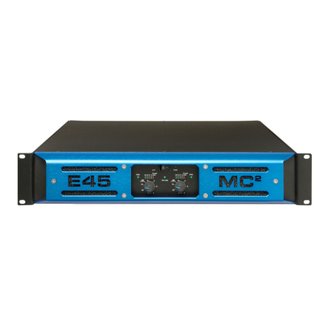
MC2 Audio MC1250 User manual

MC750
OPERATING
INSTRUCTIONS
MC
2
AUDIO Ltd.,
Units 6-8 Kingsgate,
Heathpark Industrial Estate,
HONITON,
Devon EX14 1YG
England
Tel: ++(0)1404.44633 Fax: ++(0)1404.44660
www.mc2-audio.co.uk

2
CONTENTS
TECHNICAL SPECIFICATION 3
INTRODUCTION 5
INSTALLATION Electrical 5
Mechanical 8
CONNECTIONS Inputs 8
Outputs 9
Rear panel switches 9
OPERATION Switching on 10
Level controls 10
Mute switches 10
Link switch 10
Level indicator 10
Limiters 10
Temperature control 11
Fault indicators 11
2 ohm LED 11
INTERNAL CONFIGURATION SWITCHES 12
REMOTE CONTROL OPTION 13
REMOTE CONTROL SET-UP INSTRUCTIONS 14

3
TECHNICAL SPECIFICATION
Main Specifications - MC series Amplifiers
Parameter (Units) MC1250 MC750
Output Power (per channel) (Watts)
8 ohms 850 625
4 ohms 1550 1075
2 ohms 2200 1325
Output Power (bridged) ( Watts)
8 ohms 3100 2150
4 ohms 4400 2650
THD+N:(%) (4 ohms)
@1kHz(@1dB below max output power) < 0.008 0.007
@20Hz to 20kHz(@3dB below max output power) < 0.03 0.03
Gain Options (dB)
33 31
Sensitivity Options
(for maximum power
) (dBu)
6 6
Sensitivity Options
(for maximum power)
(Volts)
1.5 1.5
Frequency Response - 20Hz to 20kHz (dB)
+0 / -0.5 +0 / -0.5
Power Consumption:
Nominal @ 240v (4 ohms)
(amps)
3.2 2.3
Power Consumption:
Nominal @ 120v (4 ohms)
(amps)
6.4 4.6
Dimensions: (mm)
Amplifier: H x W x D 130x480x460 88x480x410
Boxed (shipping UK): H x W x D 230 x 580 x 560
Boxed (shipping - all except UK): H x W x D 250 x 610 x 600 **
Weight: (Kgs)
Amplifier: 30 18.54
Boxed:(shipping) 32 20.64
Additional Specifications
Input Impedance - Active balanced (k ohms)
20 20
Input CMRR (dB)
>60 >60
Hum & Noise
(dB below max output
)
-106 -106
Damping Factor:
@1kHz into 8 ohms >400 >400
Signal Limiters -
(set to prevent excessive clipping
)
Yes Yes
Protection: Short circuit / DC output / Temperature
Yes Yes
Mains in-rush control.
Yes Yes
Output Power (watts) into 8 ohms
Sine wave @ 1kHz 575 375
Continuous music with Crest Factor of 2.8 (9dB) 850 575
Continuous music with Crest Factor of 4.8 (14dB) 850 625
Continuous music with Crest Factor of 7.8 (18dB) 850 650
Output Power (watts) into 4 ohms
Sine wave @ 1kHz 1300 800
Continuous music with Crest Factor of 2.8 (9dB) 1450 975
Continuous music with Crest Factor of 4.8 (14dB) 1550 1075
Continuous music with Crest Factor of 7.8 (18dB) 1650 1175
Output Power (watts) into 2 ohms
Sine wave @ 1kHz 1500 1300
Continuous music with Crest Factor of 2.8 (9dB) 1675 1300
Continuous music with Crest Factor of 4.8 (14dB) 2200 1325
Continuous music with Crest Factor of 7.8 (18dB) 2500 1450
** Single MC1250 orders check packing size with MC2 Audio

4
Product compliance to EC Directives
This product conforms to the relevant Directives, Regulations and Standards for electronic and
associated apparatus. The equipment is CE marked both on the apparatus and the packaging. A product
"Declaration of Conformity" statement and information regarding auxiliary apparatus and specifications
required to meet conformity is available on request from our Customer Service Department on:
+44 (0) 1404 44633
This amplifier will only operate to its very high specification if it is installed and operated as
described in this manual.

5
INTRODUCTION
Your MC750 digitally controlled power amplifier represents the latest technology in control circuitry
coupled to a no compromise high quality class AB power amplifier. There is no dynamic switching of the
audio or power rails (a very common method of achieving extra power at the expense of audio quality)
thus ensuring optimum sonic performance.
The digital control monitors the operating parameters and adjusts the amplifier to suit the conditions. Fan
speed and supply rails are varied as required to keep the amplifier within its temperature limits. The levels
are adjusted by specially selected, high performance, digitally controlled attenuators. Signal limiters are
included, the attack and release times of which can be adjusted internally by the bit switches on the
control PCB (printed circuit board).
The amplifiers include full DC and short circuit protection which automatically re-connects when the fault
is cleared.
INSTALLATION: ELECTRICAL
The amplifier has been manufactured to comply with your local power supply requirements, but before
connecting the unit to the supply, ensure that the voltage (printed on the rear panel) is correct and that a
mains fuse of the correct type and rating has been fitted.
Make sure power outlets conform to the power requirements listed on the back of the unit. Damage
caused by connecting to improper AC voltage is not covered by the warranty.
SAFETY WARNING
This unit is fitted with a 3 wire power cord. For safety reasons, THE EARTH LEAD SHOULD NOT BE
DISCONNECTED IN ANY CIRCUMSTANCE. If ground loops are encountered consult the section on
input connections later in this manual.
WHERE A FIXED MAINS LEAD IS FITTED, THE WIRING COLOURS ARE:
230V AREAS: EARTH = GREEN AND YELLOW
NEUTRAL = BLUE
LIVE = BROWN
120V AREAS: EARTH = GREEN
NEUTRAL = WHITE
LIVE = BLACK
TO PREVENT THE LIKELIHOOD OF SHOCK OR FIRE HAZARD, DO NOT EXPOSE THE UNIT
TO RAIN OR MOISTURE.
TO AVOID ELECTRICAL SHOCK DO NOT REMOVE COVERS. REFER ALL SERVICING TO
QUALIFIED PERSONNEL.
DO NOT USE THE UNIT IF THE ELECTRICAL POWER CORD IS FRAYED OR BROKEN. The
power supply cords should be routed so that they are not likely to be walked on or pinched by items
placed upon or against them, paying particular attention to cords and plugs and the point where they exit
from the appliance.
ALWAYS OPERATE THE UNIT WITH THE AC GROUND WIRE CONNECTED TO THE
ELECTRICAL SYSTEM GROUND. Precautions should be taken so that the means of grounding of a
piece of equipment is not defeated.
DO NOT REMOVE THE LID. Removing the lid will expose you to potentially dangerous voltages.
There are no user serviceable parts inside.

6
1.
Read these instructions.
2. Keep these instructions.
3. Heed all warnings.
4. Follow all instructions.
5. Do not use this apparatus near water.
6. Clean only with a dry cloth.
. Do not block any ventilation openings, install in
accordance with the manufacturer’s instructions.
8. Do not install near any heat sources, such as
radiators, heat registers, stoves or other apparatus
(including amplifiers) that produce heat.
9. Protect the power cord from being walked on or
pinched particularly at plugs, convenience
receptacles and the pint where they exit from the
apparatus.
10. The mains circuit breaker shall remain readily
accessible.
11. Only use attachments/accessories specified by the
manufacturer.
12. Use only with the cart, tripod, bracket or table
specified by the manufacturer, or sold with the
apparatus. When a cart is used, use caution when
moving the cart/apparatus combination to avoid
injury from a tip over.
13. Disconnect this apparatus during lightning storms
or when unused for a long period of time.
14.
Refer all servicing to qualified service personnel.
Servicing is required when the apparatus has been
damaged in any way, such as if the power-supply
cord or plug is damaged, liquid has been spilled or
objects have fallen into the apparatus, the
apparatus has been exposed to rain or moisture,
does not operate normally, or has been dropped.
15. Do not expose this equipment to dripping or
splashing and ensure that no objects filled with
liquids, such as vases, are placed on the
equipment.
16. To completely disconnect this equipment from the
AC mains, disconnect the power cord from the
mains circuit breaker.
1 . Where the amplifier is mounted in a rack and
permanently connected to the mains, then the rack
should be installed with a readily accessible
connector or an ALL POLE circuit breaker with 3mm
breaking distances.
18. This unit is fitted with a 3-wire power cord. For
safety reasons, THE EARTH LEAD SHOULD NOT BE
DISCONNECTED IN ANY CIRCUMSTANCE.
19. The cooling fans suck cool air in through the front
and blow hot air out at the rear of the unit through
the ventilating grills. The front and rear of the
amplifier should have free exposure to the air (i.e.
in a rack leave the front and rear doors off), with
2cm air gap at the sides and top. IF AIR IS NOT
ALLOWED TO ESCAPE FROM THE REAR, OVER-
HEATING WILL OCCUR. Take care when mounting
other equipment in the same rack.
WARNING:
Apparatus with CLASS I construction shall be connected to a MAINS socket outlet with a protective
earthing connection.
WARNING: To prevent injury, this apparatus must be securely attached to the rack in accordance with the installation
instructions.

7
1.
Lisez ces instructions.
2. Gardez ces instructions.
3. Faites attention à tous les avertissements.
4. Suivez toutes les instructions.
5. N'utilisez pas cet appareil près de l'eau.
6. Faites le ménage seulement avec un tissu sec.
. Ne bloquez pas d'ouvertures de ventilation, installez
conformément aux instructions du fabricant.
8. N'installez près d'aucunes sources de chaleur,
comme les radiateurs, les registres de chaleur, les
cuisinières ou d'autre appareil (en incluant des
amplificateurs) qui produisent la chaleur.
9. Protégez la corde de pouvoir d'être marché sur ou
pincé particulièrement aux prises de courant, les
réceptacles d'avantage et la pinte où ils sortent de
l'appareil.
10. Le disjoncteur de conduite principale restera sans
hésiter accessible.
11. Utilisez seulement des attachements/accessoires
spécifiés par le fabricant.
12. Utilisez seulement avec le chariot, le trépied, la
parenthèse ou la table spécifiée par le fabricant, ou
vendu avec l'appareil. Quand un chariot est utilisé,
utilisez la prudence en déplaçant la combinaison de
chariot/appareil pour éviter la blessure d'un bout.
13. Débranchez cet appareil pendant les tempêtes de
foudre ou quand neuf pendant un long terme de
temps.
14.
Renvoyez tout l'entretien au personnel de service
qualifié. L'entretien est exigé quand l'appareil a été
nui de toute façon, comme si la corde de pouvoir
provision ou la prise de courant sont nuis, le liquide
a été déversé ou les objets sont tombés dans
l'appareil, l'appareil a été exposé pour pleuvoir ou
l'humidité, n'opère pas normalement, ou a été
baissé.
15. N'exposez pas cet équipement au fait de tomber
goutte à goutte ou au fait d'éclabousser et
garantissez qu'aucun objet rempli des liquides,
comme les vases, n'est placé sur l'équipement.
16. Pour complètement débrancher cet équipement de
la conduite principale de courant alternatif,
débranchez la corde de pouvoir du disjoncteur de
conduite principale.
1 . Où l'amplificateur est monté dans un égouttoir et
en permanence raccordé à la conduite principale,
alors l'égouttoir devrait être installé avec un
connecteur sans hésiter accessible ou TOUT le
disjoncteur de PÔLE avec 3 millimètres cassant des
distances.
18. Cette unité est correspondue avec une corde de
pouvoir de 3 fils. Pour les raisons de sécurité,
l'AVANCE DE TERRE NE DEVRAIT ÊTRE
DÉBRANCHÉE DANS AUCUNE CIRCONSTANCE.
19. Les ventilateurs engloutissent l'air frais par le front
et soufflent l'air chaud à l'arrière de l'unité par les
grils aérants. Le front et l'arrière de l'amplificateur
devraient avoir l'exposition libre à l'air (c'est-à-dire
dans un égouttoir omettent les portes de devant et
arrière), avec le trou aérien de 2 centimètres aux
côtés et au haut. Si on NE PERMET PAS QUE D'AIR
S'ÉCHAPPE DE L'ARRIÈRE, LE FAIT DE
SURCHAUFFER SE PRODUIRA. Faites attention en
montant d'autre équipement dans le même
égouttoir.
ATTENTION
: Appareils de construction de CLASSE I doit être raccordé au réseau électrique via une prise de cou
rant
reliée à la terre.
ATTENTION: Pour éviter toute blessure, cet appareil doit être solidement fixé à la torture, conformément aux
instructions d'installation.

8
INSTALLATION: MECHANICAL
To ensure that this equipment performs to specification, it should be mounted in a suitable rack or
enclosure as described below. Like all high power amplifiers, it should be kept away from other
equipment which is sensitive to magnetic fields. Also, this amplifier may suffer a substantial reduction in
performance if it is subjected to, or mounted close to equipment which radiates high R.F. fields.
When mounting the amplifier in a rack or enclosure, ensure that :-
1. The rear of the unit is adequately supported. The brackets which are supplied fit standard 19 inch
(483mm) rack mounting systems. THE FRONT PANEL IS NOT CAPABLE OF SUPPORTING
THE UNIT ON ITS OWN.
2. THERE IS ADEQUATE VENTILATION. The cooling fans suck cool air in through the front air filter
and blow hot air out at the sides of the unit through the ventilating grills. IF THIS AIR IS NOT
ALLOWED TO ESCAPE, OVERHEATING WILL OCCUR. Take care when mounting other
equipment in the same rack. The air filter must be kept clean and free from dust. It is easily removed
by pulling it through the front. Dust can usually be shaken out, or if necessary the filter can be washed.
CONNECTIONS
INPUTS
The inputs are made via 2 separate 3 pin XLR connectors wired in parallel. Either socket can be used as
the input, the other one can be used to link to other amplifiers (‘daisy chain’) or to the other input for
mono signals.
They are electronically balanced and should be connected via a high grade twin core screened cable, as
follows:-
PIN1 - Screen (see note)
PIN2 - Hot (signal +)
PIN3 - Cold (signal -)
The amplifier is designed to operate with fully balanced equipment and ground loops or loss of
performance may be experienced if connected to unbalanced sources. If it is unavoidable however, the
following wiring should be used. The cable should still be twin core plus screen.
PIN1 - Screen - connected to the chassis of the unbalanced equipment - or left disconnected at the
unbalanced end.
PIN2 - Signal Hot
PIN3 - Signal Cold
The input requires a peak level of +6dBm for full output.
NOTE: This amplifier is wired to the latest industry recommendations. PIN1 is connected directly to
the chassis/mains earth. If ground loops (mains hum) are encountered remove the screen
connection from the other end of the cable and leave it open circuit. If problems persist,
consult your dealer/supplier, DO NOT TAMPER WITH OR ALTER ANY GROUND
(EARTH) CONNECTIONS INSIDE THE AMPLIFIER.
BRIDGED OPERATION
In Bridged mode input A is fed to both channels. Channel B will be out of phase with channel A.

9
OUTPUTS
The speaker outputs are via 4mm shrouded binding posts. They can be used with 4mm plugs or plain
wires, which can be inserted in the sides of the terminals.
Terminations are as follows:- Hot Red
Cold Black
NOTE: 1. Although the "cold" output terminals are nominally at 0V, they should not be joined
together, otherwise cross-talk may be introduced.
2. The currents involved are very high, especially when using 2 ohm. loads. The speaker
cables should be capable of carrying the currents, otherwise the losses will cause the
cables to get hot and audio power will be reduced. The minimum rating for an MC750
should be 15 amps for 4 ohm and 20 amps for 2 ohm loads.
NOTE: Do not connect the inputs/outputs to any other voltage source such as a battery, mains
source or power supply, regardless of whether the amplifier is turned on or off.
Do not run the output of any amplifier channel back into another channel’s input and
do not parallel or series-connect an amplifier output with any other amplifier output.
BRIDGED (MONO) OPERATION
Connect as follows : HOT - Channel A Hot
COLD - Channel B Hot
Leave both COLD connections open circuit, they are internally joined.
NOTE: The load impedances change when operating in the bridged mode. (See Load/Power section
below.)
LOAD/POWER SWITCH 2 ohm/4 ohm
In the 4 ohm position, the amplifier supply voltages are set up for loads of 4 ohms and above. Lower
impedance loads can be connected but the internal current limit circuit could cause clipping, and unless
the signal is very dynamic, the internal temperature rise will automatically reduce the supply voltages and
set the amplifier to the 2 ohm position. In the 2 ohm position, the supply voltages are reduced and the
level (overload) indicators and limiters are re-referenced accordingly.
When operating in bridged mode, the minimum impedances are doubled, i.e. for 4 ohm loads use
the 2 ohm position and for 8 ohm loads use the 4 ohm position. The minimum load in bridged mode
is 4 ohms.
OPERATION
Read all documentation before operating your equipment and retain all documentation for future
reference.
Do not spill water or other liquids into or on the unit and do not operate the unit while standing in liquid.
Do not block fan intake or rear ventilation outlets or operate the unit in an environment which could
impede the free flow of air around the unit.
If the unit is used in an extremely dusty or smoky environment, it should be cleaned of any collected
debris at regular intervals. (See Maintenance section.)

10
It is important that the power output of your amplifier is matched to the power handling capacity of your
loudspeaker. If not, damage to the loudspeaker could occur.
SWITCHING ON
When the amplifier is switched on, the outputs will be muted and the controller will check for any faults.
It then goes through a power up routine and finally connects the speakers to the output stages and fades up
the signal to the level at which the amplifier was previously set.
PANEL CONTROLS AND INDICATORS
Level controls
These are continuous rotary encoders which provide fine adjustment (3 turns from min. to max.). When
adjusted, the level indicators change to level control position indicators and thus the height of the LED
column shows the level position. After a second or so the LED column changes back to monitor the signal
level. This function can be changed internally via the programming switches on the control PCB. (See the
Internal Configuration section.)
Mute Switches
These are self explanatory, and require one push to mute the signal and one to un-mute - toggle action.
The LEDs indicate their status and when "un-muting" the signal is ramped (faded) up.
Link Switch
This is also a toggle action switch, the LED above indicates its status. When ON, the two level controls
are linked together and either control will adjust both channels to the same level. The controls track very
accurately and operate as stereo attenuators. The limiters are also linked. When OFF, the level controls
and limiters operate separately.
Level Indicators
These are peak reading meters which show the signal headroom before clipping. The 0dB LED is set at
approximately 1/2dB below clipping. They are referenced to the supply voltages and automatically adjust
when the supply changes. When the level controls are adjusted, the level indicators change function and
show the level control position. They return to their normal function after the level has been set.
Limiters
The MC750 incorporates digitally controlled signal limiters. They attenuate the signal via the same switch
array as the level controls and introduce virtually no distortion. The attack time, release time, threshold
level and operating mode can be set internally via the programming switches on the control PCB. (See the
Internal Configuration section.)
When the level controls are "linked" then the limiters are also linked, and when the level controls are
separate then the limiters are separate.
The amplifiers leave the factory with the limiters set up in the OVER CLIP PROTECTION mode. The
threshold is set just below the clipping point, with fast attack and release times. This is the most sonically
transparent configuration, transients are allowed to go into clipping for a few milliseconds, but if large
amounts of overdrive are applied, the limiter will attenuate the signal back to the clipping point. Low
frequency signals will be clipped as normal because of the fast release time, changing the release time to
slow will prevent low frequencies from being clipped but will change the mid and high frequency
dynamics.
The threshold can be adjusted in 1dB steps up to 3dBs below the clipping point. The limiter then behaves
like a conventional limiter, transients will be allowed to go above the threshold level but the average peak
level will be kept to the threshold point.


11
The release time can be set to infinity which changes the limiter to function as an AUTOMATIC GAIN
CONTROL. In this mode, if the signal goes above the threshold level, the gain of the amplifier will be
reduced. This reduction will remain until the level controls are manually turned back up, or until the
amplifier is switched off.
NOTE: All levels are referenced to the clipping point of the amplifier and not an actual output
voltage or power level. If the mains power drops or increases then the limit threshold will
also change, thus maintaining maximum output level.
Temperature Control
If the heat sinks get excessively hot, the controller will automatically reduce the supply voltages to the
power devices. This is totally inaudible, it does not effect the levels, but merely reduces the amplifier
headroom by about 1.5dBs. The heat generated by the heat sinks is reduced by 30%. If the amplifier is
still getting too hot there will be a further reduction. If the temperature still continues to rise the
controller will disconnect the outputs. Just before this "shutdown" point, the temperature LED will start
flashing, and it will stay on permanently whilst the amplifier is "shutdown".
The operation of the temperature LED can be changed (see Sw1, internal configuration switches below)
in the alternative position. The LED will come on as soon as the first headroom reduction point is
reached. In certain applications it is important for the user to know this. All other functions remain the
same.
Normal dynamic signals will not cause the amplifier to overheat unless the air filter is clogged or the
ventilation is inadequate. (See installation section.)
Fault Indicators
If the outputs are shorted or if DC is present, the control circuit will disengage the outputs and the fault
LED will illuminate. The controller will keep monitoring the amplifier and will reconnect the outputs and
fade up the signal when the fault is cleared.
The controller also monitors all supply voltages and the mains transformer temperature, any fault with
these will cause the amplifier to shut down and both fault LEDs will show.
2 ohm & Bridged LEDs
These indicate the position of the switches on the rear panel. The 2 ohm LED will also illuminate if the
controller senses a low impedance load (excessive temperature rise).
INTERNAL CONFIGURATION SWITCHES
As these can only be accessed by removing the top panel this should only be carried out by qualified
personnel.
The control PCB is located on the side of the unit behind the front panel. The switches are an 8 switch
DIL package at the rear of the PCB. For full description of the switches consult the Service manual.
The standard configuration is for all switches to be ON, except Sw2 and Sw6, which are normally OFF.
Sw 1 Temp LED operation. ON = Standard position, OFF = alternative position. (See
temperature control section above.)
Sw 2 (Normally OFF) This selects the auto reconnect mode. If switched OFF when a fault has
been detected, the amplifier will not reconnect the outputs even when the fault is cleared.
This is a safety requirement in certain applications.

12
Sw 3 (Normally ON) When OFF the LED columns will always show the signal level and will
not change to show the level control position when the level controls are adjusted.
Sw 4 & 5 These select the threshold level as follows:-
Sw4 Sw5
ON ON Just below clipping point.
ON OFF 1dB below clipping point.
OFF ON 2dB below clipping point.
OFF OFF 3dB below clipping point.
Sw 6 & Sw 7 operate together, they determine the operating mode and release time of the limiter as
follows:-
Sw6 Sw7 Function
OFF OFF Release time = slow
OFF ON Release time = fast
ON OFF Automatic Gain Control mode. (Once the level has
been reduced it will remain at that level until changed
manually).
ON ON Limiter disabled.
Sw 8 (Normally ON) This sets the attack time of the limiter. ON = Fast OFF = Slow
MAINTENANCE -
(ENSURE THAT ELECTRICAL POWER TO THE UNIT IS DISCONNECTED BEFORE
CARRYING OUT ANY MAINTENANCE.)
The filter behind the air intake apertures on the front of the MC range amplifiers should be cleaned or
replaced periodically, e.g. 12-24 months. (Filters in amplifiers located in more 'dirty' atmospheres may
require more frequent maintenance). The filter should be 'dry' cleaned, using a vacuum cleaner preferably.
Running the unit without a filter is not recommended unless it is within a 'clean room'. Replacement filter
material is available.
No other regular maintenance is required.
If you have any doubt about carrying out this procedure, refer to a service engineer or contact your
dealer.
IF YOUR AMPLIFIER DEVELOPS A FAULT, PLEASE REFER TO YOUR SUPPLIER FOR
SERVICE AND TECHNICAL SUPPORT. DO NOT ATTEMPT TO REPAIR THE FAULT
YOURSELF AS THIS WILL INVALIDATE THE WARRANTY.

13
REMOTE CONTROL OPTION
The MC750 is internally wired for remote control, which is easily achieved by installing the appropriate
interface/drive board during the manufacturing process, without any change to the amplifiers’
performance.
Description
The system is designed to replicate via Windows all the controls that are available on the front panel of
the amplifier (except power-on/off). This means that the volume can be turned up and down and the
channels can be linked/un-linked and muted/un-muted remotely.
Features
Up to 128 amplifiers can be ‘daisy-chained’ together from an RS485 port via an RS232-485
adaptor.
Amplifiers can be grouped together and controlled all at the same time within that group.
The front panel controls on the amplifiers can be ‘locked out’ so that they can only be controlled
from the computer. This allows the system to be set up to the client’s requirements and then made
secure against manual interference.
Two levels of security are available on the management control system through the use of
passwords, which permit a higher level access for the senior manager through one password and
more limited access at a lower level to a number of other ‘users’.
Full Windows software is available on www.download.at/mc2a
Wiring information
The interconnecting cable required is a twisted pair cable for short runs and a screened, low capacitance
data cable for long runs. The connectors are 9-way D-type and the wiring of this connector on the rear
panel complies with the standard two wire RS485 configuration as follows:
Signal Pin No.
A (+) 2 & 8
B (-) 3 & 7
Screen 5
All the ‘A’s should be joined together and all the ‘B’s joined together.
Pins 2 & 8 and 3 & 7 are joined inside the amplifier to ease the ‘daisy chain’ wiring.
The cable screen should be terminated at one place only, i.e. PIN 5 of the computer.

14
REMOTE CONTROL SET-UP INSTRUCTIONS
To set up the remote control:
Connecting the system to the controlling computer
- The RS485 adaptor is plugged into the back of the computer and the cable (which must be 2-
core with a screen) runs from this adaptor to the 9-pin D connector on the back of the first
amplifier in the sequence and then on, via 9-pin D connectors, to all other amplifiers in the
system, thus creating the daisy chain link from one amplifier to the next.
NOTE: All amplifiers in the sequence must be connected at all times to enable the selection
of any one amplifier for individual remote control.
- There needs to be a D connector at either end of the cable and connected as follows:
PIN 2 hot (positive)
PIN 3 cold (-)
PIN 5 screen
Configuring the PC
1. Launch Amplifier Explorer program (can be downloaded from www.mc2@mc2-audio.co.uk )
2. Click on the 'Tools' menu and select 'Serial link setup'.
Then: SET OPERATING SYSTEM (e.g. WIN98)
SET COM PORT NUMBER
SET PORT ADDRESS (This happens automatically.)
Set up is now complete.
Each amplifier has its own individual ID (identity) number, which is shown on a small white label under
the socket for the 9-way D connector located on the rear panel of each amplifier.
1. Click on the 'Tools' menu again and select 'New amplifier list'.
2. Check (a) 'Find all responding amplifiers' in the amplifier list box that appears.
3. Click 'START' - Amplifier Explorer will automatically search for all responding amplifiers.
4. Click on 'ICONS' in left panel to select amplifiers found.
This manual suits for next models
1
Table of contents
Other MC2 Audio Amplifier manuals

MC2 Audio
MC2 Audio S1400 User manual

MC2 Audio
MC2 Audio E100 User manual

MC2 Audio
MC2 Audio MC450 User manual

MC2 Audio
MC2 Audio E Series User manual

MC2 Audio
MC2 Audio E45 User manual

MC2 Audio
MC2 Audio HS Series User manual

MC2 Audio
MC2 Audio ti series User manual

MC2 Audio
MC2 Audio T2000 User manual

MC2 Audio
MC2 Audio Delta 40 User manual

MC2 Audio
MC2 Audio E4-75 User manual