McConnel 5 Wheel Backing Gate Drive User manual
1
Owners Manual
McCONNEL
5 Wheel Backing Gate Drive
(Recommended for backing gates 10 to 14m long)
3-Phase and 1-Phase
Electric Powered
WARNING
Never operate your backing gate with people in the yard.

2
Limited Warranty
K H McConnel Ltd. (McConnel) warrants to the purchaser of a new Gate Drive Unit, that it will be free from
defects in material and workmanship for a period of one (1) year from the date of purchase, subject to the
following terms and conditions.
1. Remedies
During the limited warranty period McConnel or it’s authorised service agent will repair or replace, at
McConnel's option, any defective products or parts thereof with new or factory rebuilt replacement items.
All replaced parts or product shall become the property of McConnel.
Repaired product will be warranted for the balance of the original warranty.
2. Place of Repair
For repair under warranty the Gate Drive Unit must be returned to McConnel or their authorised service agent.
This warranty does not include freight, travel time or travel time associated with transporting the gate drive to or
from McConnel or their authorised service agent. No charge will be made for parts or the labour in repairing or
replacing the product.
3. Exclusions
The warranty does not apply if the Gate Drive Unit becomes faulty due to:
-Operation at voltages other than those shown on the motor name plate.
-Improper installation
-Misuse
-Neglect
-Accident
-Act of God
-Unauthorised repair or modification
-Service performed by other than competent persons
The warranty also does not apply if the purchaser fails to:
-Obtain a “warranty service authorisation number” from McConnel prior to having remedial work done.
-Notify McConnel within the warranty period.
4. Electric Motors
Proof of mains connection by a registered electrician is required for the warranty to include the electric motor.
This should be provided by your electrician at the time of installation.
This warranty only covers new electric motors supplied and fitted by McConnel to the Gate Drive Unit.
5. Wheels
The limited warranty covers the bond of the rubber to the rim and the rim only. No warranty is given on the life
of the rubber itself.
6. Limitation of Liability
McConnel accepts no responsibility for consequential loss, damage or injury to person or property arising from
any defect in the Gate Drive Unit or the installation to which it is connected.
7. Making a Warranty Claim
Should a fault occur during the warranty period, the purchaser must in the first instance telephone McConnel
(+64 7 849 2122) to obtain a “Warranty Service Authorisation Number”. The following information will be re-
quired; a. Purchasers name
b. Physical address where the gate drive is installed
c. Serial number of the Gate Drive Unit (Top of the gear casing opposite oil filler plug)
d. Place and date of purchase
e. Installing electrician if electric powered.
After discussion of the problem and available local service agents McConnel will initiate servicing under the
terms of this warranty.

3
Contents
Safety Pg 4
Installation Requirements
Yard Design Pg 4
Gate Design Pg 4
Gate Drive Installation
Mounting the Gate Drive Pg 5
Front Wheel Alignment Pg 5
Lubrication Pg 5
Electrical Supply and Wiring Pg 9
Optional Overload Clutch Adjustment Pg10
Spare Parts Diagrams
Gate Drive Exploded View Pg 6
Gear Casing Exploded View Pg 8
Motor Assembly Exploded View Pg 9
Operating Instructions
General Pg11
Free wheel clutch operation Pg11
Maintenance
Monthly Maintenance Pg12
Wheel replacement Pg12
Oil Change Pg12
Optional Overload Clutch Pg12
Warning: All gate drives are shipped without oil.
Please fill the gear casing to the sight glass
with (approx. 4 litres) SAE EP 90 grade gear oil
before use.

4
Safety
Never operate your backing gate with people in the yard.
McCONNEL backing gate drives are designed to move heavy
animals. If people are accidentally subject to the same loads,
serious injury may result.
Your holding yard should be designed to avoid trap points
where an animal may become trapped between the backing
gate and a fixed object.
Installation Requirements
Yard Design
The Gate drive unit is designed for operation on a circular or semi cir-
cular concrete surface with an even drainage fall, free of steps or
drainage channels. An uneven surface can cause premature failure of
the wheels and stop the gate from moving by lifting the drive wheels
off the ground.
Gate Design
The backing gate should be of sturdy construction capable of with-
standing the bending and torsional loads that will be applied to it. For
animal safely care should be taken to avoid diagonal bracing where a
cow may get its leg trapped in the vee that is created.
Putting a hock rail on the gate is recommended. This is a rail the
length of the gate that protrudes in front of the gate at a height of 500
to 600mm above the ground (depending on cow size and breed) that
prevents cows from holding the gate up with a straight leg. The hock
rail should not be too low or the cows lower leg and feet may be dam-
aged.
Ensure the motor or pelton wheel and freewheel clutch lever are ade-
quately protected from damage if cows are held on both sides of the
gate.

5
Gate Drive Installation
Correct attachment and alignment of your gate drive will greatly re-
duce the maintenance required over the life of your backing gate.
Mounting the Gate Drive
Position the assembled gate drive under the backing gate, within 1m
of the moving end with the drive wheels behind the gate away from the
cows being crowded. Position the gate across the centre of the mount
saddle and align the rear wheel shaft with the center post with the aid
if a string line (see figure 1). Double check alignment before welding
the mount saddle securely to the gate. The mount saddle is 255mm
above ground level.
Front Wheel Alignment
Next align the front shaft with the center post. Do this by lifting the gate
in a safe manner, until the front wheel is just clear of the ground.
Loosen the front shaft mount bolts and using a string line from the cen-
ter post as a guide, align the front wheel shaft so it points directly to-
wards the center post (see figure 1). Tighten the front shaft bolts and
lower the gate to the ground again.
Lubrication
All gate drives are shipped without oil.
Please fill the gear casing to the sight glass with
(approx. 4 litres) SAE EP 90 grade gear oil before use.
The filler plug is located on top of the gear casing.
Figure 1: Gate drive attachment to gate and alignment of wheels
Center Post
Mount
Saddle
Front shaft alignment
Rear shaft alignment

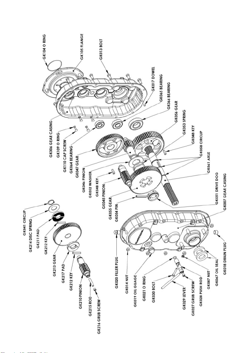
6
Gate Drive Exploded View

7
8
/ GK008 GEAR CASING WITH OPTIONAL OVERLOAD CLUTCH
Optional
Overload Clutch
Replaces GK047 GEAR
and GK045 PINION
Gear Casing Exploded View

9
Motor Assembly Exploded View
Electrical Supply and Wiring
Three phase motors are dual voltage and can be configured for use on
the following three phase power supplies;
230v 50Hz (1.9A) or 260v 60Hz (1.9A), delta connection.
400v 50Hz (1.1A) or 460v 60Hz (1.9A), star connection.
Be sure to install the terminal connectors correctly for star or delta
connection in accordance with motor name plate and instructions on
the motor terminal cover.
Single phase motors should only be connected to a 230v 50 Hz power
supply.
To prevent moisture entering the motor from the wiring;
If the conduit is terminated at the cast cover, the cable must be
sealed at the motor terminal box to IP55 specifications.
If the conduit is terminated at the motor terminal box, the entire
conduit including both ends must be sealed to IP55 specifications.
10
Water Supply
A suitable water supply must be available for the entire milking season
at a water pressure of approx. 40 psi (2.75 bar) and flow rate of 20 gal-
lons per minute (90 l/min) at the gate drive. Each water wheel on the
gate drive has a nozzle with a 25mm tail to attach the water supply to.
The supply line should be made self draining to prevent freezing in
cooler areas.
When run off a pressurised water supply, the gate drive can be con-
trolled by operation of a simple ball valve or a solenoid valve. Where a
pump is required the gate drive can be controlled by the pump starter.
For two-way water powered gate drives, it is convenient to have two
supply lines and select the forward or reverse supply form the milking
shed.
The power of the gate drive can be adjusted by restricting or increas-
ing the water flow to the gate drive. For example, reducing water flow
can reduce excessive wheel spin.
More predictable and convenient control is possible with a purpose
built controller such as a McConnel ‘Guardian’ Backing Gate Control-
ler.
For 3/4 circle yards a loop of flexible hose at the center post gives
enough movement to prevent the feed hose kinking through the gates
travel. For full circle yards, as when two gates are used in one yard, a
center post gland such as a McConnel 2” Wash Union will be required.
Operating Instructions
For 3/4 yards, a loop of flexible cable (approx 1m) is needed at the
transition from centre post to the gate, to reduce the bending stress on
the cable and prevent the cable cores breaking down. This loop must
be suitably supported and protected. For full circle yards, where the
gates are able to continue the next rotation without reversing, an elec-
trical slip ring at the center post is recommended.
A simple forward-off-reverse switch can be used to operate the back-
ing gate from one location in the shed or a combination of selector
switch for forward-reverse and pull switch for on-off will enable opera-
tion from any location in the pit. More predictable and convenient con-
trol is possible with a purpose built controller such as a McConnel
‘Guardian’ Backing Gate Controller.
Optional Overload Clutch
This gate drive can be fitted with an optional friction overload clutch for
added safety during milking.
Adjustment is done from outside the gear casing as follows:
1. Ensure the oil level is up to the sight glass.
2. Chain the end of the backing gate securely to a yard post with the
gated drive wheels on a clean yard.
3. Remove the overload cover plug (GK016) from the gear casing.
See Figure 2 on page 11.
4. Insert a 5mm AF Allen key into the adjusting screw and turn it anti
-clockwise until all tension is released from the clutch.
Caution: For safety, always stand behind the backing gate for
parts 5 to 8 of this procedure.
5. Get an assistant to start the gate drive in the forward direction.
6. Turn the Allen key clockwise to slowly tighten the clutch until the
electric motor starts to stall or the drive wheels begin to slip and
stop the gate drive. Note: the Allen key will rotate if the wheels slip
on the yard.
7. Turn the clutch adjustment back a 1/8th turn anti-clockwise.
8. Replace the cover plug taking care not to over tighten it.
9. Finally untie the gate.
Adjustment is required before use.

11
Operating Instructions
General
A backing gate is intended to prompt cows into the milking shed. To do
this it is recommended that the gate be used in short frequent move-
ments to prevent overcrowding in the yard. The backing gate should
never be left crowding cows that cannot move.
Free Wheel Clutch
All gate drives are fitted with a free wheel clutch to allow manual
movement of the gate. The clutch must be fully disengaged before
moving the gate manually or damage to the clutch may result. Also the
clutch should not be operated when the gate is in powered operation
or when the gate is being pushed.
Re-engage the clutch by releasing the clutch lever when the gate is
stationary and push the gate slowly until the clutch re-engages. Do not
start powered operation of the gate again until the clutch is fully en-
gaged.
Remove plug to
adjust overload
clutch
Figure 2: Overload Clutch Adjustment Location

12
Maintenance
Your gate drive is a robust unit designed to give many years of reliable
service if operated and maintained properly.
Monthly Maintenance
Check oil level and top up with SAE EP90 or equivalent grade
gear oil as required.
Grease front wheel bearing.
Check wheel wear. Replace the rim if it is worn down to the
aluminium. Failure to replace wheels at this time may result in
permanent damage to the gear casing.
Check for any loose fasteners or damage.
Wheel Replacement
It is recommended that the drive wheels be replaced as a set to pre-
vent uneven loading on the gate drive unit.
Oil Change
Change oil every 5 years or if milky due to water contamination.
Optional Overload Clutch
Adjust yearly or if the gate drive looses power. Instructions on Pg 10.
Manufactured and distributed by;
K. H. McCONNEL Ltd
666 Te Rapa Road
P O Box 10-334
Hamilton 3241
New Zealand
Phone: +64 7 849 2122
Fax: +64 7 849 2128
Email: sales@mcconnel.co.nz
Table of contents
Other McConnel Gate Opener manuals


