McGuire SPXFLOW FLEX Series User manual

FLEX Series
Refrigerated Type Compressed Air Dryers
Models: DFX 8.1, DFX 12.5, DFX 15.1, DFX 20.1
FORM NO.: 7473076 REVISION: 08/2019 READ AND UNDERSTAND THIS MANUAL PRIOR TO OPERATING OR SERVICING THIS PRODUCT.
INSTRUCTION MANUAL
MCGUIRE AIR COMPRESSORS INC
1-888-229-9999
MCGUIRE AIR COMPRESSORS INC
1-888-229-9999

Contents
INTRODUCTION .................................................................................................. 1
SAFETY............................................................................................................... 1
INSTALLATION ..................................................................................................... 1
HOW IT WORKS .................................................................................................. 3
CONTROLLER...................................................................................................... 3
START-UP/OPERATION........................................................................................ 4
MAINTENANCE................................................................................................... 5
FIELD SERVICE GUIDE......................................................................................... 6
ENGINEERING DATA ........................................................................................... 7
DRAWINGS
General Arrangement
Model: DFX 8.1 ........................................................................................... 8
Models: DFX 12.5, DFX 15.1 ....................................................................... 9
Model: DFX 20.1 ......................................................................................... 10
Electrical Schematic....................................................................................... 11
Air and Refrigerant Flow Schematic
Model: DFX 8.1 ........................................................................................... 12
Models: DFX 12.5, DFX 15.1, DFX 20.1 ....................................................... 13
REPLACEMENT PARTS........................................................................................ 14
MAINTENANCE KITS ........................................................................................... 14
NOTES................................................................................................................ 15
WARRANTY
MCGUIRE AIR COMPRESSORS INC
1-888-229-9999
MCGUIRE AIR COMPRESSORS INC
1-888-229-9999

1
INTRODUCTION
Compressed air is generated by compressing atmospheric
air of which contains moisture and other containments, into
high pressure air. After compression, the air is not saturated
but when it is cooled by the aftercooler, the relative humidity
becomes 100%.
As compressed air travels down the pipe line and cools further,
moisture starts to condensate into liquid water. Condensate
water in the pipe line is harmful to the manufacturing process
as it causes rust or sludge etc.
In order to avoid this problem, the only solution is to dry the
compressed air with an air dryer. Refrigerated compressed air
dryers are used as a cost effective and energy efficient solu-
tions for eliminating moisture from the compressed air system.
The discovery of using Phase Change Material (PCM) as a com-
ponent in the refrigerated compressed air dryer to produce
latent heat has encouraged great energy savings. Through
latent heat properties, it is able to save up to 99% of energy at
no load condition. This is indeed a breakthrough in refrigerated
compressed air dryer technology.
SAFETY
The dryers are designed and built with safety as a prime con-
sideration; industry accepted safety factors have been used in
the design. Each dryer is checked at the factory for safety and
operation. All necessary adjustments are made before shipment.
Follow the maintenance schedules outlined in this manual for
good performance and safe operation.
Only qualified personnel with proper tools should do mainte-
nance.
Safety instructions in this manual used to indicate hazard
seriousness levels are classified as follows:
Immediate hazard which WILL result in severe injury or
death.
Hazard or unsafe practice which COULD result in severe
injury or death.
Hazard or unsafe practice which COULD result in minor
injury or product damage.
Carefully read the following safety rules before proceed-
ing with installation, operation or maintenance. The rules
are essential to ensure safe dryer operation. Failure to
follow these rules may void the warranty or result in dryer
damage or personal injury.
1. Do not install or try to repair a dryer that has been damaged
in shipment. See Receiving and Inspection for instructions.
2. Compressed air and electricity have the potential to cause
personal injury or equipment damage. Before doing any
work on the dryer, be sure the electrical supply has been
locked and tagged and the internal pressure of the dryer
has been vented to the atmosphere.
3. Do not operate the dryer at pressures or temperatures
above the maximum conditions shown on the data plate.
4. Always supply electrical power that complies with the volt-
age shown on the data plate.
5. Do not readjust the dryer without factory authorization.
6. Do not operate the dryer with any dryer cabinet panel
removed.
Cooling air flow across the condenser may be reduced
if a dryer panel has been removed while the dryer
is operating, resulting in the dryer not functioning
properly and/or dryer failure. Failure to follow these
instructions may result in a non-warrantable dryer
failure.
7. Only a competent refrigeration mechanic works on the
refrigeration system.
8. Use only manufacturer’s genuine replacement parts. The
manufacturer bears no responsibility for hazards caused
by the use of unauthorized parts.
INSTALLATION
Inspect the dryer closely when it is received. Record any indica-
tion of damage on the delivery receipt, especially if the dryer
will not be immediately uncrated. Obtain the delivery person’s
signed agreement to recorded damages to facilitate future
insurance claims .
Since the dryer is shipped F.O.B. Factory, the manufacturer’s
responsibility for the shipment ceases when the carrier signs
the bill of lading.
If goods are received short or in damaged condition, notify the
carrier and insist on a notation of the loss or damage across
the face of the freight bill. Otherwise no claim can be enforced
against the carrier.
If concealed loss or damage is discovered, notify your carrier
at once and request an inspection. This is absolutely necessary.
Unless you do this, the carrier will not consider any claim for
loss or damage. The carrier will make an inspection and may
grant a concealed damage notation. If you give the carrier a
clear receipt for the goods that have been damaged or lost in
transit, you do so at your own risk and expense.
The manufacturer is willing to assist you in collecting claims for
loss or damage. Willingness does not make the manufacturer
responsible for collecting claims or replacing material. Claim
filing and processing is your responsibility.
MCGUIRE AIR COMPRESSORS INC
1-888-229-9999
MCGUIRE AIR COMPRESSORS INC
1-888-229-9999

2
Ambient Air Temperature
Locate the dryer indoors where the ambient air temperature will
be between 39°F (4°C) and 122°F (50°C). Intermittent operation
at ambient temperatures up to 122°F (50°C) will not damage the
dryer but may result in a higher dew point or dryer shutdown
due to high refrigerant discharge pressure (see Field Service
Guide). Call your local distributor if prolonged operation at
ambient temperatures above 122°F (50°C) or below 39°F (4°C)
is unavoidable.
Do not operate air-cooled dryers at ambient air temperatures
below 39°F (4°C). Such operation may result in low suction pres-
sure, causing freeze-up.
Location and Clearance
Mount the dryer on a level base and bolt down if the base vi-
brates. If the dryer is air cooled, install it in a clean, well-ventilated
area to reduce fouling of the condenser coils with dirt and dust.
Allow 48 inches (1220 mm) clearance on the sides and the front
of the dryer for cooling airflow and service access.
System Arrangement
Liquid water adversely affects dryer performance. To prevent
“slugging” the dryer with liquid water, locate the dryer down-
stream of an aftercooler and a mechanical separator. Install
drain valves to discharge condensate that collects in these areas.
If the airflow is relatively constant and will not cause short term
overloading of the dryer, it is recommended that the dryer be
located downstream of the receiver tank. If the nature of the
application is such that the air demand regularly exceeds the
dryer flow rating, it is recommended that the dryer be located
upstream of the receiver.
For safety and convenience, install inlet and outlet shutoff
valves and depressurization valves at the locations indicated.
These valves allow the dryer to be isolated and depressurized
for servicing. Bypass piping may be installed around the dryer
for uninterrupted airflow when the dryer is serviced. If the com-
pressed air operation cannot tolerate wet air for short periods,
install a second dryer in the bypass line.
Compressed air systems commonly require filters to remove
compressor oils, particulates, condensed liquids and other
contaminants. When an oil-removal filter is used, install the
filter downstream of the dryer. At this location, the life of the
replaceable filter element is prolonged since the dryer removes
some of the entrained oil and drained through the separator.
Piping and Connections
The user must furnish piping unless otherwise specified. Con-
nections and fittings must be rated for the maximum operating
pressure given on the dryer data plate and must be in accor-
dance with applicable codes. Support all piping; do not allow
the weight of any piping to stress the dryer or filters. Inlet and
outlet shutoff valves and bypass valves are recommended. Pip-
ing should be at least the size of the inlet and outlet connections
to minimize pressure drop in the air system. See Specification
Table for dryer inlet and outlet connections.
Drains
Condensate must be drained from the dryer to prevent an influx
into outlet air. The FLEX dryers are equipped with an automatic
no loss drain valve and internal drain hoses up to the drain con-
nections on the dryer cabinets.
The user must install a discharge line from the drain connection
and run it to a waste disposal collection system that meets ap-
plicable regulations. Pipe or copper tubing 1/2 inch or larger is
recommended for condensate discharge lines. Install the drain
lines so that condensate can be seen as it drains.
NOTE: Discharge is at system pressure. Drain line should be
anchored.
NOTE: Condensate may contain oil. Comply with applicable laws
concerning proper disposal.
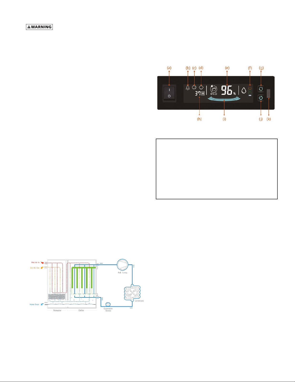
Drain Valve Operation
A. Verify that isolation valves are open. If the drain fails to
discharge after the valve is energized, the electronic control
circuit will repeatedly energize the valve in an attempt to
clear the discharge port. If, after 60 seconds, the drain still
fails to discharge, the control circuit then switches to the
alarm mode. In this mode the valve is de-energized and the
red alarm light is activated on the drain. The valve is then
automatically energized every 4 minutes for 5 seconds.
Check the drain operation. Push drain (push-to-test) button
on the drain or the Electronic Controller (if equipped) to
energize drain. A flow of condensate and/or air should be
present at the drain outlet. The alarm mode automatically
clears after the drain returns to normal operation.
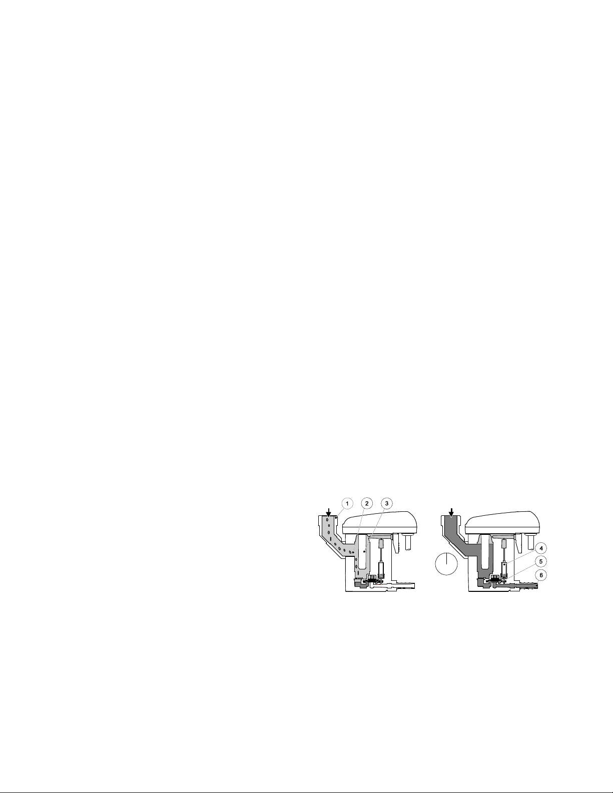
B. The condensate flows through the feed line (1) into the
condensate drain and accumulates in the housing (2). A
capacitive sensor (3) continuously registers the liquid level.
As soon as the container is filled, a fixed waiting period
begins during which more condensate accumulates. After
the waiting time has expired the pilot valve (4) is then ac-
tivated and the diaphragm (5) opens the outlet line (6) for
discharging the condensate.
When the condensate drain has been emptied, the outlet
line is closed again quickly and tightly without wasting
compressed air.
Figure 1.
Schematic diagram of the no loss drain valve
MCGUIRE AIR COMPRESSORS INC
1-888-229-9999
MCGUIRE AIR COMPRESSORS INC
1-888-229-9999

3
Electrical Connections
Operation of dryers with improper line voltage constitutes
abuse and could affect the dryer warranty.
The dryers are constructed according to NEMA Type 1 electrical
standards. Field wiring must comply with local and national fire,
safety and electrical codes. Installation must be in accordance
with the National Electrical Code. Confirm that your line voltage
is the same as the voltage listed on the dryer data plate. Refer
to Figure 5 electrical schematics.
HOW IT WORKS
Phase Change Mechanism of the FLEX Dryer
1. When the refrigeration compressor and the condenser fan
are running, the cold refrigerant in the chiller (evaporator)
cools the liquid Phase Change Material (PCM) which gradu-
ally solidifies.
2. When the PCM is sufficiently cooled and solidified, the
refrigeration compressor and condenser fan will stop.
3. The compressed air is continuously cooled by the PCM
while the refrigeration compressor is inactive. No power
is consumed during this period.
4. The PCM gradually liquefies as it adsorbs heat from the
compressed air, and when fully melted, the refrigeration
compressor and condenser fan resume to cool the PCM.
Compressed Air flow
The dryers use refrigeration cooling to condense entrained
moisture out of the air stream. Warm saturated air enters the
air-to-air heat exchanger where it is cooled by outgoing cold
air. The inlet air is further cooled in the refrigeration chiller. The
condensate is removed from the air stream by an electronic
drain valve.
The cold, dry air is reheated by incoming warm air as it passes
back through the air-to air heat exchanger. Using the outgo-
ing air to pre-cool the inlet air condenses up to 65 percent of
the moisture out of the inlet air before it reaches the chiller.
Pre-cooling the inlet air reduces the heat load on the refriger-
ant compressor, permitting the use of a smaller refrigerant
compressor.
Figure 2.
Schematic diagram of the compressed air flow and
refrigerant
CONTROLLER
The controller provides ease of monitoring and operating
status for Energy Savings (%), dryer operating time, refrigera-
tor compressor operating time, and active fault message dew
point status. The controller also provides advanced functions
like communication and operating status data storage.
Figure 3.
Controller
a: DRYER ON/OFF SWITCH
b: ALARM LIGHT
c: REFRIGERANT COMPRESSOR RUNNING LIGHT
d: DRYER RUNNING LIGHT
e: ENERGY SAVING RATIO (%)
f: DEWPOINT TEMPERATURE INDICATOR
g: RUNNING TIME SELECT BUTTON
h: DRYER RUNNING / REFRIGERANT COMPRESSOR RUNNING TIME
i: ENERGY SAVING (GRAPH)
j: TIMER BUTTON (LEVEL 2 ONLY)
k: MICRO-USB CONNECTION PORT (LEVEL 2 ONLY)
Controller Functions
1.
Dryer On/Off
2. Display energy saving ratio (%)
3. Display alarm signal
4. Display dryer and refrigerant compressor running time
5. Display dew point level by indicator
6. Save the operating data
a. Refrigerant compressor on/off status, Alarm, Dew
point level, Inlet air temperature
b. Memory chip can save maximum 30 days
c. When there is no space to save, then erase the first
one
7. MICRO-USB connection port
a. Automatically download operating data
b. Automatically upgrade firmware program
8. Communication port
a. RS485: Modbus monitoring
MCGUIRE AIR COMPRESSORS INC
1-888-229-9999
MCGUIRE AIR COMPRESSORS INC
1-888-229-9999

4
3. Check proper connection and support of compressed air
lines to the dryer; check bypass valve system, if installed.
4. SLOWLY pressurize the dryer. The outlet valves of the dryer
should be closed to prevent flow through the dryer.
5. Turn on the main electrical power to the dryer.
6. Ensure adequate ventilation for air cooled dryers.
7. Do not operate the dryer with any dryer cabinet panel
removed.
Cooling air flow across the condenser may be reduced
if a dryer panel has been removed while the dryer
is operating, resulting in the dryer not functioning
properly and/or dryer failure. Failure to follow these
instructions may result in a non-warrantable dryer
failure.
To start dryer
IMPORTANT: Energize dryer for 24 hours prior to starting
refrigerator compressor! Failure to follow these instruc-
tions may result in a non-warrantable compressor failure.
1. Turn the power switch to ON. The refrigerant compressor
will turn on.
2. Allow the dryer to run 15 minutes. Confirm that the tem-
perature indicators are in the green zone.
3. SLOWLY open the dryer outlet valves permitting flow
through the dryer.
4. Confirm that condensate is discharging from the drain valve
by pressing the “Push-to Test” button (on drain).
5. Confirm that the inlet air temperature, pressure and airflow
to the dryer meet the specified requirements (see Engi-
neering Data section).
6. Confirm that the condensate lines from the drain valve
discharge into a collection tank or an environmentally ap-
proved disposal system.
The FLEX dryer is designed to run and stop repeatedly. Let the
FLEX dryer operate even when the demand for compressed air
is interrupted; the FLEX dryer will not freeze up.
Shutdown
When the dryer must be shutdown for maintenance or other
reasons, use the following procedure.
1. Turn off the power switch.
2. Disconnect the main power supply.
3. Lock out and tag the power supply in accordance with OSHA
requirements.
If mechanical repairs are to be made or service is performed,
vent the internal pressure of the dryer to atmospheric pressure.
Restart the dryer according to the start-up instructions.
Disconnect power supply and depressurize dryer before
servicing. Dismantling or working on any component of
the compressed air system under pressure may cause
equipment failure and serious personal injury.
Operation
1. To start the dryer, turn on the (a) dryer on/off switch.
2. When the refrigeration compressor and the condenser fan
are running, the cold refrigerant in the chiller (evaporator)
cools the liquid Phase Change Material (PCM) which gradu-
ally solidifies. During this time, the refrigeration compressor
running light (c) is illuminated on the LCD window.
3. Energy saving percent (e) is displayed on the LCD window
by calculating dryer running time and refrigeration com-
pressor operating time.
4. Pressure dew point level (f) is displayed on the LCD window.
5. Dryer running time (h) is displayed on the LCD window while
the power is on. Pressing (g) will toggle the compressor
running time where the dryer running time (h) was dis-
played. When the (j) button is pressed and held for over 10
seconds, dryer and compressor running times are erased
and displayed “0 H”. (timer reset)
6. Check the dryer operating status when the alarm light (b)
blinks according to Table 1 below.
No. Alarm display Description
1 lamp (b) blinks rapidly
and “E01” is displayed
on (h)
Ref. compressor has
no signal
2 lamp (b) blinks and
“E02” is displayed on
(h)
Temperature sensor
signal open
3 lamp (b) light is on
“E03” is displayed on
(h)
Drain valve has some
trouble
Table 1. Alarm display mode
START-UP/OPERATION
Never use the disconnect switch to shut down the dryer
for an extended period of time (except for repair). Failure
to follow these instructions may result in a non-warrant-
able compressor failure.
IMPORTANT: Energize dryer for 24 hours prior to starting
refrigerator compressor! Failure to follow these instruc-
tions may result in a non-warrantable compressor failure.
Follow the procedure below to start your dryer. Failure to follow
the prescribed start-up procedure will invalidate the warranty.
If problems arise during start-up, call your distributor. Before
repair, vent the internal pressure of the dryer to atmospheric
pressure.
Before starting dryer
Drain connections must be made before the dryer can be op-
erated. The dryers are fully automatic and require no auxiliary
controls.
1. Turn the dryer on/off switch to off.
2. Check that the main electrical supply voltage matches the
voltage specified on the dryer data plate.
MCGUIRE AIR COMPRESSORS INC
1-888-229-9999
MCGUIRE AIR COMPRESSORS INC
1-888-229-9999

5
MAINTENANCE
The FLEX Dryer requires little maintenance for satisfactory opera-
tion. Good dryer performance can be expected if the following
routine maintenance steps are taken.
General
For continued good performance of your refrigerated dryer,
all refrigeration system maintenance should be performed by
a competent refrigeration mechanic.
NOTE: Before corrective maintenance is done during the war-
ranty period, call your local distributor and proceed according to
instructions. Refer to the warranty for limits of your coverage.
Daily Maintenance
Check the operation of the no loss drain valve at least once
daily. See the Field Service Guide for remedies to drain valve
malfunctions.
Monthly Maintenance
It is recommended to inspect the condenser coils monthly.
If necessary, remove dirt or other particles with compressed
air from an OSHA-approved air nozzle that limits its discharge
pressure to 30 psig (2.1 kgf/cm
2
).
Yearly Maintenance
It is recommended to replace the drain service unit annually.
For units purchased with a filtration package, replace prefilter
and afterfilter elements annually.
Maintenance kits are available to facilitate annual maintenance.
Vent Drain Valve
The vent drain valve is located in the air inlet pipe to allow for
the draining of liquid that may build there under low flow
conditions. In the event the outlet pressure dew point exceeds
normal values during low load conditions, open the valve for no
more than 5 seconds to remove the liquid and reclose the valve.
NOTE: Condensate may contain oil. Comply with applicable laws
concerning proper disposal.
Disconnect power supply and depressurize dryer before
servicing. Dismantling or working on any component of
the compressed air system under pressure may cause
equipment failure and serious personal injury.
MCGUIRE AIR COMPRESSORS INC
1-888-229-9999
MCGUIRE AIR COMPRESSORS INC
1-888-229-9999

6
FIELD SERVICE GUIDE
PROBLEM SYMPTOM POSSIBLE CAUSE REMEDY
Water downstream of
dryer.
No discharge from no loss drain
valves.
Drain valve failure or accumulation
of dirt in drain valve strainer.
Dismantle drain valve: clean, repair or replace.
See maintenance section.
Inlet air temperature is too high. Aftercooler malfunction. Check aftercooler discharge temperature.
Reduce temperature to 122°F (50°C) max.; reduce
airflow if temperature is above 95°F (35°C).
Liquid water entering dryer. Aftercooler drain valve malfunction. Dismantle aftercooler drain valve; clean, repair or
replace.
Excessive airflow (may also cause
high pressure drop).
Dryer improperly sized. Check airflow and dryer capacity (See Engineering
Data Tables).
Reduce airflow or resize and replace dryer.
Compressor cuts out on internal
overload.
Inadequate ventilation of refriger-
ant compressor.
Ensure adequate ventilation of the condensing unit
(see Clearance).
Motor will restart automatically when compressor
is cool.
Leak in refrigeration system. Locate leak, repair and recharge. Motor will restart
automatically when compressor is cool.
Compressor windings read open or
shorted.
Compressor burned out. Have a refrigeration mechanic check and replace.
The dew point level is red on LCD
window.
Inlet air temperature too high. Reduce aftercooler discharge temperature to design
conditions (See Engineering Data Tables).
Excessive airflow. Check airflow and system capacity. Reduce airflow or
resize and replace system.
Condenser fouled or clogged. Clean or replace condenser.
Fan motor inoperative. Replace fan motor.
High ambient temperature. Ventilate area.
See Engineering Data Tables.
High pressure drop
across dryer.
Inlet air temperature is too low. Low ambient temperature. Consult your local distributor.
Excessive airflow (may also cause
water downstream of dryer).
Dryer improperly sized. Check airflow and dryer capacity. Reduce airflow or
resize and replace dryer.
Dryer icing up. Adjust operating conditions to meet sizing condi-
tions.
No condensate from
no loss drain valve.
Valve venting. But no condensate
from valve.
Accumulation of dirt in valve
strainer.
Dismantle valve strainer.
Clean or replace Strainer.
Valve continuously venting. Clogged valve orifice. Replace valve.
Short in electrical component. Check and replace connector or controller assembly.
Valve not cycling. No electrical power. Check and correct power supply and connections.
Drain valve malfunction. Replace drain valve.
No response when test button is
pushed.
No electrical power. Check and correct power supply and connections.
Fuse burned out. Check solenoid coil and wiring cable and replace
fuse.
MCGUIRE AIR COMPRESSORS INC
1-888-229-9999
MCGUIRE AIR COMPRESSORS INC
1-888-229-9999

7
ENGINEERING DATA
MODEL DFX 8.1 DFX 12.5 DFX 15.1 DFX 20.1
Air System Data
Rated Air Flow at 100°F & 100 psig Inlet, 100°F Ambient (scfm) 800 1250 1500 2000
Minimum / Maximum Inlet Compressed Air Pressure 44 / 232 psig (3.0 / 16.0 barg)
Minimum / Maximum Inlet Compressed Air Temperature 39° / 122°F (4° / 50°C)
Minimum / Maximum Ambient Temperature 36° / 113°F (2° / 45°C)
Refrigeration System Data
Refrigerant Type R-407C
Refrigerant Charge See Data Tag on Dryer
Compressor High Pressure Switch Setting (cut out / cut in) 406 psig / Manual Reset (31.0 barg / Manual Reset)
Air-Cooled Condensers
Air Flow Across Condenser (cfm) 4,710 5,650 10,240 11,180
Condenser Fan Switch Setting (cut in / cut out) 217.5 / 275.6 psig (15 / 19 barg)
Electrical Data
Nominal Voltage 460/3/60
Input Power @ Rated Flow (watts) 4,300 7,600 9,000 10,000
Minimum Circuit Ampacity 9.8 16.5 16.9 20.4
Maximum Overcurrent Protector (amps) 17.1 28.9 28.5 34.6
Compressor Rated Load Amps 7.3 12.4 11.6 14.2
Compressor Locked Rotor Amps 42 80 98 130
CORRECTION FACTORS (MULTIPLIERS)
Air Inlet Temperature
°F (°C) Multiplier Air Inlet Pressure
psig (barg) Multiplier Ambient Air Temperature
°F (°C) Multiplier
80°F (27°C)
90°F (32°C)
100°F (38°C)
110°F (43°C)
120°F (49°C)
1.46
1.23
1.00
0.82
0.68
75 psig (5.2 bar)
100 psig (6.9 bar)
120 psig (8.3 bar)
150 psig (10.3 bar)
225 psig (15.5 bar)
0.86
1.00
1.04
1.09
1.15
80°F (27°C)
90°F (32°C)
100°F (38°C)
110°F (43°C)
120°F (49°C)
1.12
1.06
1.00
0.83
0.68
MCGUIRE AIR COMPRESSORS INC
1-888-229-9999
MCGUIRE AIR COMPRESSORS INC
1-888-229-9999

8
DRAWINGS: GENERAL ARRANGEMENT
Figure 4A
Model: DFX 8.1
MODEL
DIMENSIONS, INCHES (MM) INLET/OUTLET
CONNECTIONS
WEIGHT
Lb. (kg)
A B C D E F G H J
DFX 8.1 10.85
(276)
19.69
(500)
6.18
(157)
29.92
(760)
31.50
(800)
58.59
(1488)
3.94
(100)
54.02
(1372)
50.08
(1272) 3” ANSI Flange 1133
(514)
HOLE FOR MAIN POWER
DRAIN OUTLET
4-Ø10 MOUNTING HOLES
FOOT PRINT
HG
C
F
A
B
E
J
VENT DRAIN VALVE D
WETTED AIR INLET
DRIED AIR OUTLET
COOLING
AIR
FLOW
COOLING
AIR
FLOW
LEFT SIDE VIEW
TOP VIEW
REAR VIEW FRONT VIEW
MCGUIRE AIR COMPRESSORS INC
1-888-229-9999
MCGUIRE AIR COMPRESSORS INC
1-888-229-9999

9
DRAWINGS: GENERAL ARRANGEMENT
Figure 4B
Models: DFX 12.5, DFX 15.1
MODEL
DIMENSIONS, INCHES (MM) INLET/OUTLET
CONNECTIONS
WEIGHT
Lb. (kg)
A B C D E F G H J
DFX 12.5 10.85
(276)
19.69
(500)
6.09
(155)
37.80
(960)
39.37
(1000)
58.59
(1488)
3.94
(100)
57.09
(1450)
53.15
(1350) 4” ANSI Flange 1537
(697)
DFX 15.1 10.85
(276)
19.69
(500)
6.09
(155)
37.80
(960)
39.37
(1000)
58.59
(1488)
3.94
(100)
57.09
(1450)
53.15
(1350) 4” ANSI Flange 1766
(801)
HOLE FOR MAIN POWER
DRAIN OUTLET
4-Ø10 MOUNTING HOLES
HG
A
F
E
B
C
J
D
FOOT PRINT
VENT DRAIN VALVE
TOP VIEW
LEFT SIDE VIEWREAR VIEW FRONT VIEW
DRIED AIR OUTLET
WETTED AIR INLET
COOLING
AIR
FLOW
COOLING
AIR
FLOW
MCGUIRE AIR COMPRESSORS INC
1-888-229-9999
MCGUIRE AIR COMPRESSORS INC
1-888-229-9999

10
DRAWINGS: GENERAL ARRANGEMENT
Figure 4C
Model: DFX 20.1
MODEL
DIMENSIONS, INCHES (MM) INLET/OUTLET
CONNECTIONS
WEIGHT
Lb. (kg)
A B C D E F G H J
DFX 20.1 10.85
(276)
19.69
(500)
6.09
(155)
37.80
(960)
39.37
(1000)
58.59
(1488)
3.94
(100)
63.78
(1620)
59.84
(1520) 4” ANSI Flange 2028
(920)
HOLE FOR MAIN POWER
DRAIN OUTLET
4-Ø10 MOUNTING HOLES
FOOT PRINT
HG
A
B
F
E
C
J
D
VENT DRAIN VALVE
TOP VIEW
LEFT SIDE VIEWREAR VIEW FRONT VIEW
DRIED AIR OUTLET
WETTED AIR INLET
COOLING AIR FLOW
MCGUIRE AIR COMPRESSORS INC
1-888-229-9999
MCGUIRE AIR COMPRESSORS INC
1-888-229-9999

11
DRAWINGS: ELECTRICAL SCHEMATIC
Figure 5
LEGEND
MC1: Magnetic Contactor
MC2: Magnetic Contactor
MC3: Magnetic Contactor
F.P.S: Fan Pressure Switch
H.P.S: High Pressure Switch
TH1: Thermal Overload Relay
TH2: Thermal Overload Relay
TH3: Thermal Overload Relay
S1: Switch “On-Off”
Q1: Cut Off Switch
TS1: Separator Inlet Temp. Sensor
TS2: Heat Exchanger Inlet Temp. Sensor
TS3: Air Inlet Temp. Sensor
CP1: Circuit Protector
DRAIN TRAP: No Loss Drain Valve
PCB: Control Board
PMR: Phase Monitoring Relay
1
DIP SW
2 3 4
TR S
MC1
COMP.
0V
480V
0V
120V
460V/3PH/60HZ
W1U1 V1
E
2
1
MAIN POWER
TH1
AC IN COMP ALARM DRAIN
COMONR1 S1FG S2 R2 COM ON COM N.CN.0
TS3 TS2
DRAIN
TRAP
24 21 12 25
20 30
TS1
DRAIN
TRAP
20
30
32 31
32 31
T0R0 S0
R0
T0
TR
TRANSFORMER
100VA
60Hz
CP1(2A)
CRANK CASE HEATER
MC1
3
4
20
30
33 34 35
RS232 RS485
4
2
3
24 21 12 25
Q1
T0R0 S0
USE COPPER SUPPLY WIRES
FAN
W2U2 V2
MC2
TH2
MOTOR
#1
FAN
MOTOR
#2
W3U3 V3
MC3
TH3
H.P.S
TH1
MC1
25 11 11
MC2
TH2 26
PMR 27
MC3
36
TH3
11
28
MC1 12
PCB
COM.
N.O.
N.C.
PMR 11
14
24
27
T
S
R
I>
S1
F.P.S
DFX15.1/DFX20.1 USE ONLY
DFX15.1/DFX20.1
USE ONLY
24
MCGUIRE AIR COMPRESSORS INC
1-888-229-9999
MCGUIRE AIR COMPRESSORS INC
1-888-229-9999

12
DRAWINGS: AIR AND REFRIGERANT FLOW SCHEMATIC
Figure 6A
Model: DFX 8.1
COMPRESSED AIR FLOW
REFRIGERANT FLOW
BRAZED PLATE HEAT EXCHANGER
TEMP. SENSOR1
TS1
<REF-PCM-AIR>
WETTED AIR INLET
DRIED AIR OUTLET
<AIR-AIR>
DRAIN VALVE
DRAIN OUTLET
NO LOSS
VALVE
EXPANSION DEVICE
TEMP. SENSOR2
TS2
SEPARATOR FILTER
TEMP. SENSOR3
TS3
MANUAL
REFRIGERANT COMPRESSOR
CONDENSER
COOLING AIR FLOW
AIR COOLED
FILTER
CONDENSER
AIR COOLED
HIGH PRESSURE SWITCH
SET : 406 psig
(28 barg) FAN
COOLING AIR FLOW
FAN
FAN PRESSURE SWITCH
SET : 217.5 psig - 275.6 psig
(15 - 19 barg)
H.P.S
F.P.S
MCGUIRE AIR COMPRESSORS INC
1-888-229-9999
MCGUIRE AIR COMPRESSORS INC
1-888-229-9999

13
DRAWINGS: AIR AND REFRIGERANT FLOW SCHEMATIC
Figure 6B
Models: DFX 12.5, DFX 15.1, DFX 20.1
COMPRESSED AIR FLOW
REFRIGERANT FLOW
REFRIGERANT COMPRESSOR
TEMP. SENSOR1
TS1
WETTED AIR INLET
DRIED AIR OUTLET
CONDENSER
COOLING AIR FLOW
EXPANSION DEVICE
AIR COOLED
TEMP. SENSOR2
TS2
TEMP. SENSOR3
TS3
FILTER
CONDENSER
AIR COOLED
HEAT EXCHANGER
<AIR-AIR>
<REF-PCM-AIR>
REHEATER
CHILLER
BRAZED PLATE
HEAT EXCHANGER
BRAZED PLATE
DRAIN VALVE
DRAIN OUTLET
NO LOSS
VALVE
SEPARATOR
MANUAL
FAN
COOLING AIR FLOW
FAN
HIGH PRESSURE SWITCH
SET: 406 psig
(28 barg)
FAN PRESSURE SWITCH
SET: 217.5 psig - 275.6 psig
(15 - 19 barg)
REF. RECEIVER
H.P.S F.P.S
MCGUIRE AIR COMPRESSORS INC
1-888-229-9999
MCGUIRE AIR COMPRESSORS INC
1-888-229-9999

14
Phone: +1 724 745 1555
Email: ft.dehydration.order.entry@spxflow.com
Web: www.spxflow.com/deltech
REPLACEMENT PARTS
DFX 8.1 DFX 12.5 DFX 15.1 DFX 20.1
Part Name
Refrigerant Compressor 7439958 7439960 7472992 7472993
Condenser 7439967 7439967 7439967 7472994
Fan Motor 7439971 7472996 7472997 7472998
Fan Grill (Ext.) 7440000 7472999 7473000 7473001
Filter Dryer 7439962 7439962 7439962 7439962
High Pressure Switch 7433678 7433678 7433678 7433678
Fan Pressure Switch 7473002 7473002 7473002 7473002
No Loss Drain Valve 7440053 7440053 7440053 7440053
Controller 7473003 7473003 7473003 7473003
On/Off Switch 3209745 3209745 3209745 3209745
Receiver — 7473004 7473005 7473006
Separator 7473007 7473008 7473008 7473009
White Temperature Sensor 7440388 7440388 7440388 7440388
Red Temperature Sensor 7440389 7440389 7440389 7440389
Yellow Temperature Sensor 7440390 7440390 7440390 7440390
MAINTENANCE KITS
Model Kit Components DFX 8.1 DFX 12.5 DFX 15.1 DFX 20.1
Standard Kit No Loss Drain Valve Repair Kit,
Drain Cover
DFXMK
(7461666)
DFXMK
(7461666)
DFXMK
(7461666)
DFXMK
(7461666)
Standard Kit
with Filtration
Package
No Loss Drain Valve Repair Kit,
Drain Cover, Prefilter Element(s),
Afterfilter Element(s), Filter Drain Valve
Repair Kit (2)*
DFX8.1-FPMK*
(7473054)
DFX12.5-FPMK*
(7473055)
DFX15.1-FPMK*
(7473056)
DFX20.1-FPMK
(7473057)
* Filter Drain Valve Repair Kits are ONLY included with model size DFX 8.1, DFX 12.5, and DFX 15.1 Maintenance Kits with Filtration Package Option.
MCGUIRE AIR COMPRESSORS INC
1-888-229-9999
MCGUIRE AIR COMPRESSORS INC
1-888-229-9999

15
NOTES
MCGUIRE AIR COMPRESSORS INC
1-888-229-9999
MCGUIRE AIR COMPRESSORS INC
1-888-229-9999

MCGUIRE AIR COMPRESSORS INC
1-888-229-9999
MCGUIRE AIR COMPRESSORS INC
1-888-229-9999

WARRANTY
The manufacturer warrants the product it manufactures, when properly installed, operated, applied, and maintained in accordance with
procedures and recommendations outlined in manufacturer’s instruction manuals, will be free from defects in material or workmanship
for a period as specified below, provided such defect is discovered and brought to the manufacturer’s attention within the aforesaid
warranty period.
The manufacturer will repair or replace any product or part determined to be defective by the manufacturer within the warranty period,
provided such defect occurred in normal service and not as a result of misuse, abuse, neglect or accident. Normal maintenance items
requiring routine replacement are not warranted. The warranty covers parts and labor for the warranty period unless otherwise specified.
Repair or replacement shall be made at the factory or the installation site, at the sole discretion of the manufacturer. Although not required
for warranty consideration, it is recommended that the manufacture be contacted prior to doing any warranty related service work. This
action will provide guidance and instruction on the repair often times authorization to perform the work. NOTE: The manufacture reserves
the right to repair, replace in the case of warranty approval or reject the warranty claim once submitted.
Unauthorized service and use of unauthorized or pirated parts voids the warranty and any resulting charges or subsequent claim will
not be paid. Products repaired or replaced under warranty shall be warranted for the unexpired portion of the warranty applying to the
original product.
The foregoing is the exclusive remedy of any buyer of the manufacturer’s product. The maximum damages liability of the manufacturer
is the original purchase price of the product or part.
THE FOREGOING WARRANTY IS EXCLUSIVE AND IN LIEU OF ALL OTHER WARRANTIES, WHETHER WRITTEN, ORAL, OR STATUTORY, AND IS EXPRESSLY
IN LIEU OF THE IMPLIED WARRANTY OF MERCHANTABILITY AND THE IMPLIED WARRANTY OF FITNESS FOR A PARTICULAR PURPOSE.
THE MANUFACTURER SHALL NOT BE LIABLE FOR LOSS OR DAMAGE BY REASON OF STRICT LIABILITY IN TORT OR ITS NEGLIGENCE IN WHATEVER
MANNER INCLUDING DESIGN, MANUFACTURE OR INSPECTION OF THE EQUIPMENT OR ITS FAILURE TO DISCOVER, REPORT, REPAIR, OR MODIFY
LATENT DEFECTS INHERENT THEREIN. THE MANUFACTURER, HIS REPRESENTATIVE OR DISTRIBUTOR SHALL NOT BE LIABLE FOR LOSS OF USE OF
THE PRODUCT OR OTHER INCIDENTAL OR CONSEQUENTIAL COSTS, EXPENSES, OR DAMAGES INCURRED BY THE BUYER, WHETHER ARISING FROM
BREACH OF WARRANTY, NEGLIGENCE OR STRICT LIABILITY IN TORT.
Please note that the manufacturer’s warranty for this product is intended to cover manufacturing defects and therefore does not cover
consumable components (desiccants, filter elements, soft goods, standard maintenance kit wear items, etc.) or components that require
periodic user adjustment (expansion valve, hot gas bypass valve or cooling water regulating valve) or calibration (dew point elements/
sensors, gauge calibration, etc.)
Warranty Period
Parts and labor for two (2) years from the date of shipment from the factory.
An extended warranty of up to 5 years from the date of purchase may be available for your dryer. Please contact your local distributor for
more details of the requirements for activation of warranty extension.
AUTHORIZATION FROM THE SERVICE DEPARTMENT IS NECESSARY BEFORE MATERIAL
IS RETURNED TO THE FACTORY OR IN-WARRANTY REPAIRS ARE MADE.
SERVICE DEPARTMENT: (724) 746-1100
MCGUIRE AIR COMPRESSORS INC
1-888-229-9999
MCGUIRE AIR COMPRESSORS INC
1-888-229-9999

SPX FLOW
4647 S.W. 40th Avenue
Ocala, Florida 34474-5788 U.S.A.
P: (724) 745-1555
E: ft.dehydration.order.entry@spxflow.com
www.spxflow.com/deltech
Improvements and research are continuous at SPX FLOW, Inc.
Specifications may change without notice.
ISSUED 08/2019 Form No.: 7473076 Revision: None
COPYRIGHT ©2019 SPX FLOW, Inc.
FLEX Series
Refrigerated Type Compressed Air Dryers
Models: DFX 8.1, DFX 12.5,
DFX 15.1, DFX 20.1
MCGUIRE AIR COMPRESSORS INC
1-888-229-9999
MCGUIRE AIR COMPRESSORS INC
1-888-229-9999
This manual suits for next models
4
Table of contents
Popular Air Compressor manuals by other brands

Sullair
Sullair E900H user manual

DeVilbiss Air Power Company
DeVilbiss Air Power Company Ex-Cell E7540 Operation manual

California Air Tools
California Air Tools 20040DCAD owner's manual

Stanley
Stanley AIRPRO 120 CDC120SCA instruction manual

Gardner Denver
Gardner Denver ELECTRA-SAVER ESMF Operating and service manual

Pittsburgh Automotive
Pittsburgh Automotive 63184 Owner's manual & safety instructions