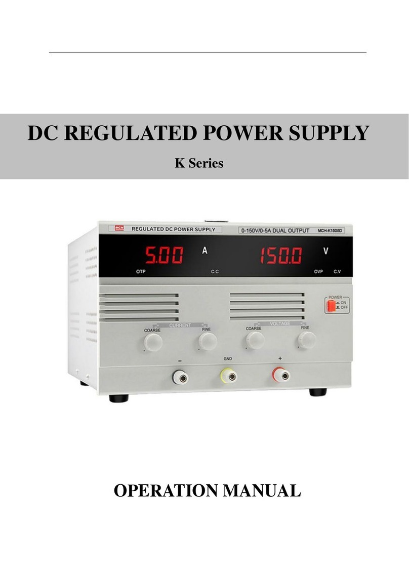
3.1 Functions of the controls on front panel
(1)(2) 3 or 4 digit LED display.
(3)(4) CV and CC indicators. If the current (calculated by
Ohm’s law) through the load is lower than the preset current
value of the power supply, CV indicator lights, the power
supply is working in Constant Voltage status. Otherwise, CC
indicator lights, the power supply is in Constant Current
status. And the actual current though the load is limited to
the preset current value.
(5) Independent/Series/Parallel Controls. When the power
supply is set in series mode, two channels are connected
serially. Voltage of Channel A will follow that of Channel B.
Then a pair of same value and different polarity voltage is
acquired, and you can get a doubled voltage from positive
port of CH-B and negative port of CH-A. When the power
supply is set in parallel mode, two channels are connected
parallel. And you can get a doubled current from either port
o f t w o c h a n n e l s .
(6) Power switch.
(7)(8) Voltage adjustment. If in tracking state, the switches
of channel A are not available.
(9)(10) Current adjustment, to set constant current value.
(11) Output port No.1, fixed 5V/1A output.
(12) Output port No.2, it is controlled by switch (7) and (9).
(13) Output port No.3, it is controlled by switch (8) and (10).
5


