Schaudt EBL 263-5 Instruction Manual

Operating Instruction Manual
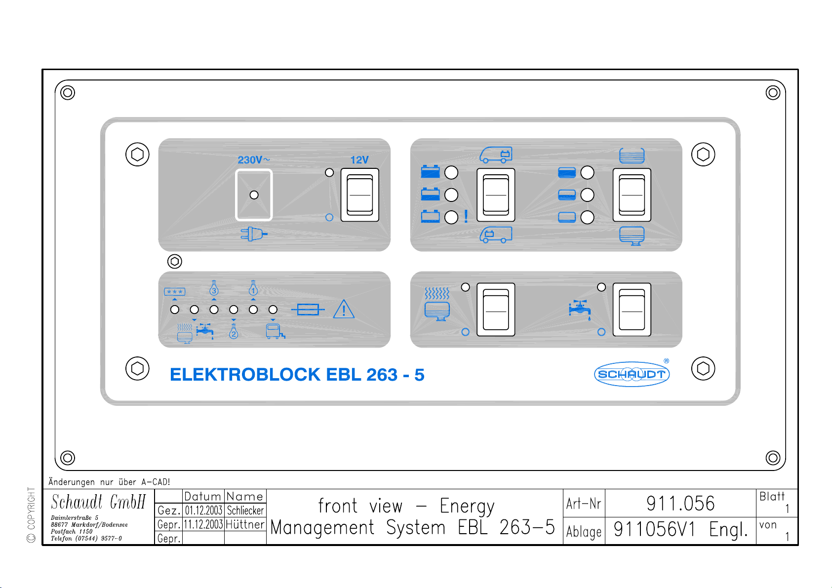
Elektroblock EBL 263-5 Art no 911.056 page 1 /10
Note: this operating instruction manual is intended for the customer and has to be supplied with the device
Schaudt GmbH, Elektrotechnik & Apparatebau, Daimlerstraße 5, D-88677 Markdorf, Tel +49 7544 9577-0, Fax +49 7544 9577-29, www.schaudt-gmbh.de 18.05.2004
Contents
1. Description
2. Safety Information
3. Operating Instructions
4. Transport, Storage, Installation
5. Electrical Installation
6. Power-Up, Shut-Down, Maintenance
7. Malfunction
8. Enclosure
1. Description
The Elektroblock EBL 263-5 is an energy management system for motor homes. It is a combination of
a battery charger, a 12V distribution box and a control and switch panel.
It contains the charging module LA 204, a battery monitor, the complete 12V distribution, fuse-protected
12V circuits and additional control and monitoring devices.
The controls and switches on the front panel, control the living-area functions of the motor home and
indicate certain values like voltages or filling levels.
Tank sensors are necessary to measure the filling levels of the water tanks. Please do order separately.
Note: The EBL 263-5 is not suitable for filling level measurement of metal water tanks.
1.1 Suitable Accessories
rod tank sensors 2 rod tank sensors, 2 sensor cables 4 x 0.5
2 seal rings art no 126.007, 2 check nuts art no 102.106
or tank sensors 8 tank sensors, art no 933.662, 2 sensor cables 4 x 0.5
1.2 Technical Data
1.2.1 General Data
sizes front panel: 290 x 155
cabinet: 275 x 130 x 173 (W x H x D in mm)
weight 4.4 kg
cabinet PA (Polyamide), Gentian blue RAL 5010
front panel aluminium, powder painted, white aluminium RAL 9006
1.2.2 Electrical Data
mains supply * 230V (+ 6 / - 10%), 50Hz, safety class 1
current draw * 230VA
suitable batteries * 6 cell lead-acid or lead-gel batteries, from 35Ah
quiescent current * max 0.6mA
off living-area battery
load current of alternator's * approx 0.3A
D+ output by EBL
permissible load on * maximum current draw up to the fuse rating of each output;
12V outputs see enclosed block diagram.
Operating Instruction Manual
Elektroblock EBL 263-5 Art no 911.056 page 2 /10
Note: this operating instruction manual is intended for the customer and has to be supplied with the device
Schaudt GmbH, Elektrotechnik & Apparatebau, Daimlerstraße 5, D-88677 Markdorf, Tel +49 7544 9577-0, Fax +49 7544 9577-29, www.schaudt-gmbh.de 18.05.2004
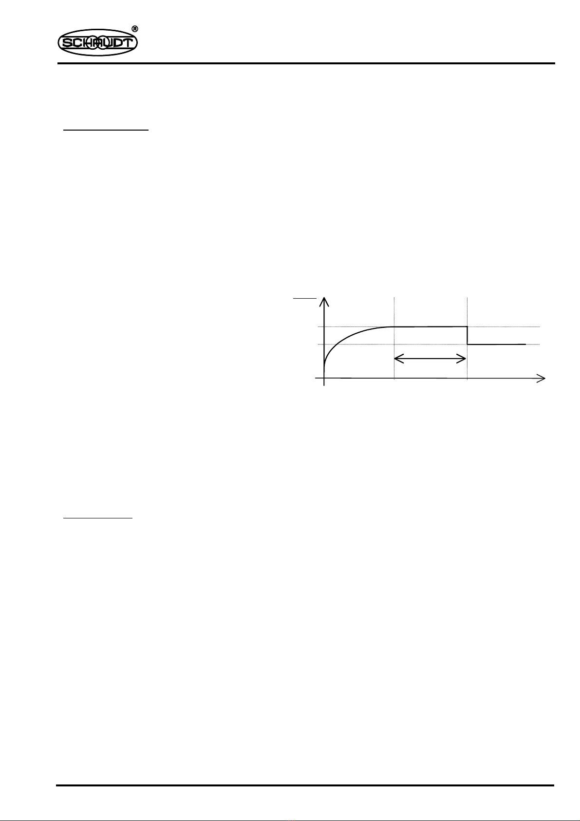
1.2.2.1 Battery charging ...
... on mains supply
living-area battery:
control system * thyristor controller
charging characteristic * IWUoU
charging current * 10A arithmetic mean or 15A eff at 230V mains supply and 12.0V
charging voltage. The charging current is mains supply dependent.
maximum charging voltage * 14.4V
float voltage * 13.8V, automatic change-over
new charging cycle,
change-over to boost-charge * when battery voltage is about < 13.8V
IW boost-charge at max 10A arithmetic
mean, electronically limited, up to
maximum charging voltage
Uo then equalize-charge at constant 14.4V
selectable: 20 minutes duration for lead-
acid, 6h duration for lead-gel batteries
Uthen automatic change-over to float-
charge at 13.8V
If due to high loads the float voltage of 13.8V cannot be provided, the battery charger switches over
from float to boost-charge.
safety circuits * short-circuit and reverse-polarity protected,
charger needs a connected battery with a voltage of > 2.5V
* safety fuse in mains circuit, 1.6A slow
* over-temperature switch in transformer
starter battery:
charging current * trickle-charge to starter battery with max 2A
... while driving
charging current * simultaneous charging of starter and living-area battery by alternator,
batteries in parallel by cut-off relay, maximum charging current into the
living-area battery must not exceed 30A, see block diagram.
1.2.2.2 Battery Monitor Module
switch-off voltage * approx 10.5V
minimum reset voltage
for 12V main-switch on
instrument panel * approx 11.0V
time
U charge
V
20min with lead-acid
6h with lead-gel
'boost-charge'
I
'float'
U
'equalize'
Uo
14.4
13.8
charging characteristic of EBL 263-5

Operating Instruction Manual
Elektroblock EBL 263-5 Art no 911.056 page 3 /10
Note: this operating instruction manual is intended for the customer and has to be supplied with the device
Schaudt GmbH, Elektrotechnik & Apparatebau, Daimlerstraße 5, D-88677 Markdorf, Tel +49 7544 9577-0, Fax +49 7544 9577-29, www.schaudt-gmbh.de 18.05.2004
2. Safety Information
* The electrical installation of the motor home has to be in accordance with current DIN-, VDE- and
ISO-regulations. Alterations will endanger the safety of persons and the vehicle. Due to the above
mentioned regulations and safety rules, alterations are, therefore, prohibited.
* The connection of the EBL to the mains supply has to be in accordance to national installation rules.
* The Elektroblock EBL 263-5 must not be modified.
* The connection of the Elektroblock should be carried out by qualified personnel only and must be
conform to specifications mentioned in this operating instruction manual:
see instruction manual section 4.2 'Installation'
section 5 'Electrical Installation'
and in enclosure schematic diagram of EBL 263-5
* In the following text special notice should be paid to the signs shown below:
Caution !
Electrical current hazard warning.
Caution !
General hazard warning.
3. Operating Instructions
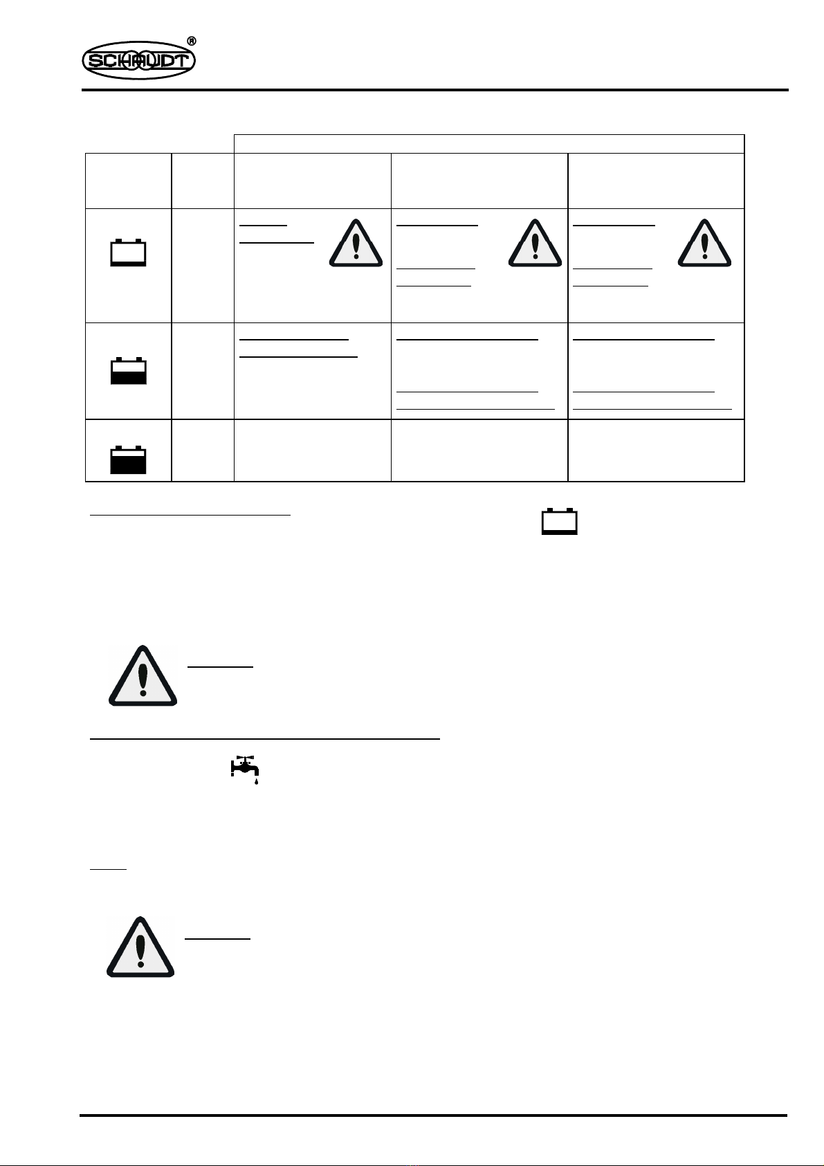
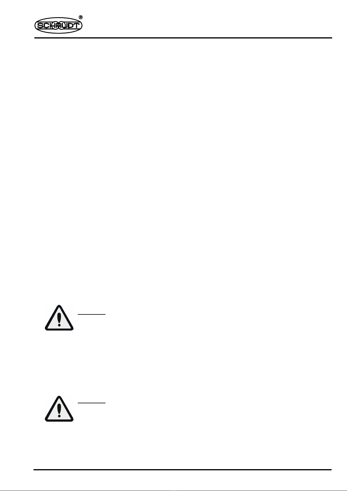
3.1 Controls and Indicators
To turn on and off 12V supply of living-area
Actuate switch with 12V symbol ...
... up →12V supply of living area is turned on. Green indicator lamp is on.
... down →12V supply of living area is turned off. Green indicator lamp is off.
Note: The circuit 'automatic step' is not switched by the 12V main switch.
Caution !
To avoid unnecessary discharge of the living-area battery the 12V supply should be
switched off when leaving the vehicle.
Inquiry of battery voltage
LED indication of battery voltage in three levels.
Actuate switch in direction of →Living-area battery condition is indicated.
Actuate switch in direction of →Starter battery condition is indicated.
Operating Instruction Manual
Elektroblock EBL 263-5 Art no 911.056 page 4 /10
Note: this operating instruction manual is intended for the customer and has to be supplied with the device
Schaudt GmbH, Elektrotechnik & Apparatebau, Daimlerstraße 5, D-88677 Markdorf, Tel +49 7544 9577-0, Fax +49 7544 9577-29, www.schaudt-gmbh.de 18.05.2004
!
Evaluation of 'LED battery indicator'
Vehicle ...
LED
Indicators
Battery
Voltage
... is parked.
Without mains supply
Runs on battery
... is driving or engine
idles.
... is connected to
mains supply.
Runs on 230V.
red <10.9V Battery
discharged
Caution:
total discharge
No charging
Or
12V system
overloaded
Caution:
total discharge
No charging
Or
12V system
overloaded
Caution:
total discharge
yellow 10.9V
to
12.3V
Weakly charged
battery or on load
Low charging current
if continuous
(for several hours):
Low charging current or
12V system overloaded
Low charging current
if continuous
(for several hours):
Low charging current or
12V system overloaded
green >12.3V Battery
properly charged
Standard charge Standard charge
Low voltage warning indicator
Optical warning of a alarming low living-area battery charge.
As soon as the living-area battery voltage drops below 10.8V the red warning light starts blinking.
Any load must now be switched off immediately and the living-area battery should be recharged.
Recharging can be done by running the engine or connecting the EBL to mains supply.
See section 1.2.2.1 'Battery charging ...'
Caution !
Total discharge or overcharging might permanently damage the battery.
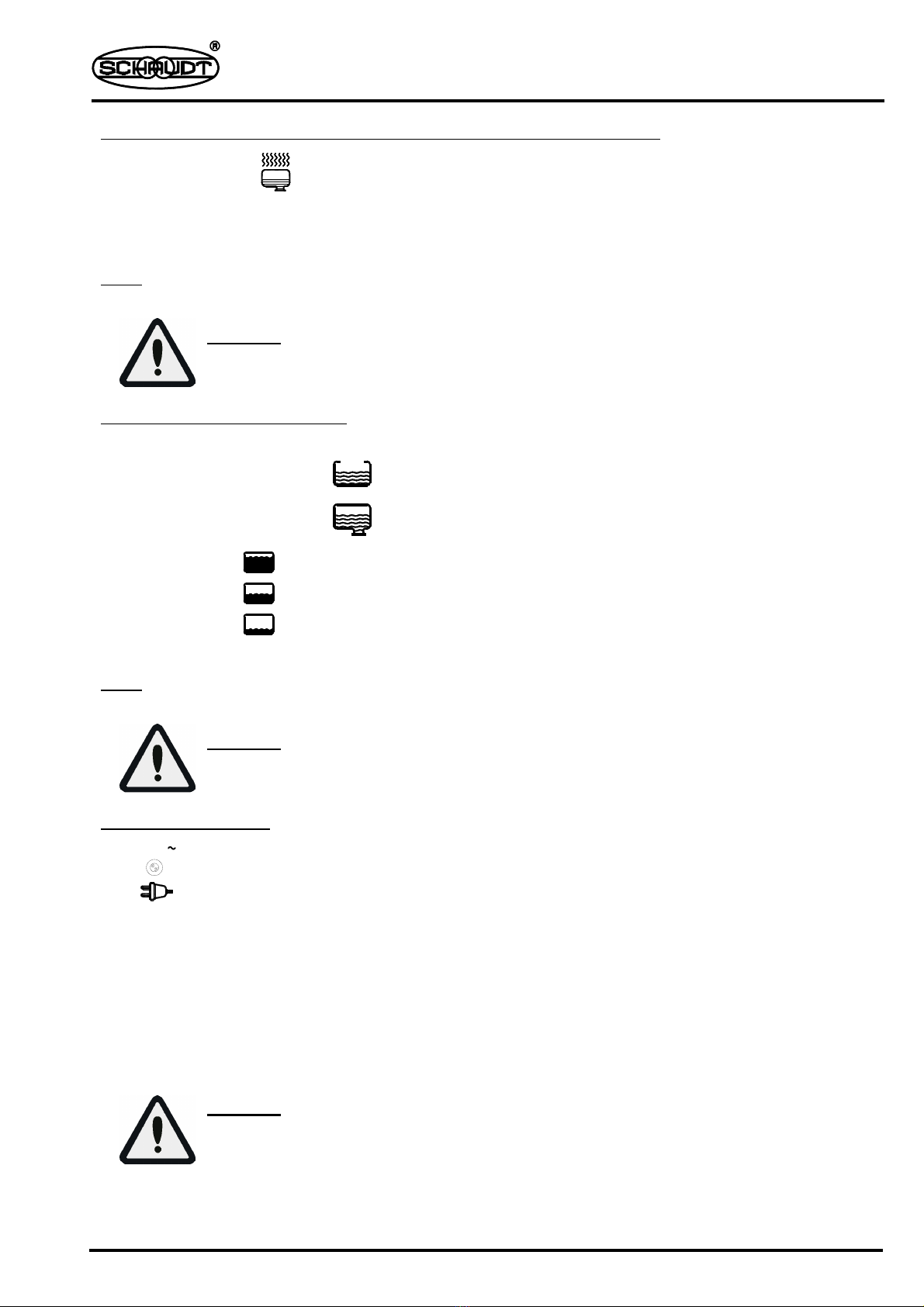
To switch on and off the water pump's power supply
Actuate switch with symbol ...
... up →The water pump may be switched on. Yellow indicator lamp is on.
... down →The water pump can not be switched on. Yellow indicator lamp is off.
Note: The power supply of the water pump should be turned off during long disuse, eg at night, as the
pump relay has a current consumption of approx 160mA. This adds up to about 4Ah battery drain
per day.
Caution !
Creepage current discharge of living-area battery with pump switch on.
Operating Instruction Manual
Elektroblock EBL 263-5 Art no 911.056 page 5 /10
Note: this operating instruction manual is intended for the customer and has to be supplied with the device
Schaudt GmbH, Elektrotechnik & Apparatebau, Daimlerstraße 5, D-88677 Markdorf, Tel +49 7544 9577-0, Fax +49 7544 9577-29, www.schaudt-gmbh.de 18.05.2004
230V
To switch on and off the power supply of the waste water heater (optional)
Actuate switch with symbol ...
... up →The waste water heater may be switched on. Yellow indicator lamp is on.
... down →The waste water heater cannot be switched on. Yellow indicator lamp is off.
Note: The waste water heater needs a considerable amount of power.
When used for long periods, the motor home should be on mains supply.
Caution !
Discharge of living-area battery with waste water heater switched on.
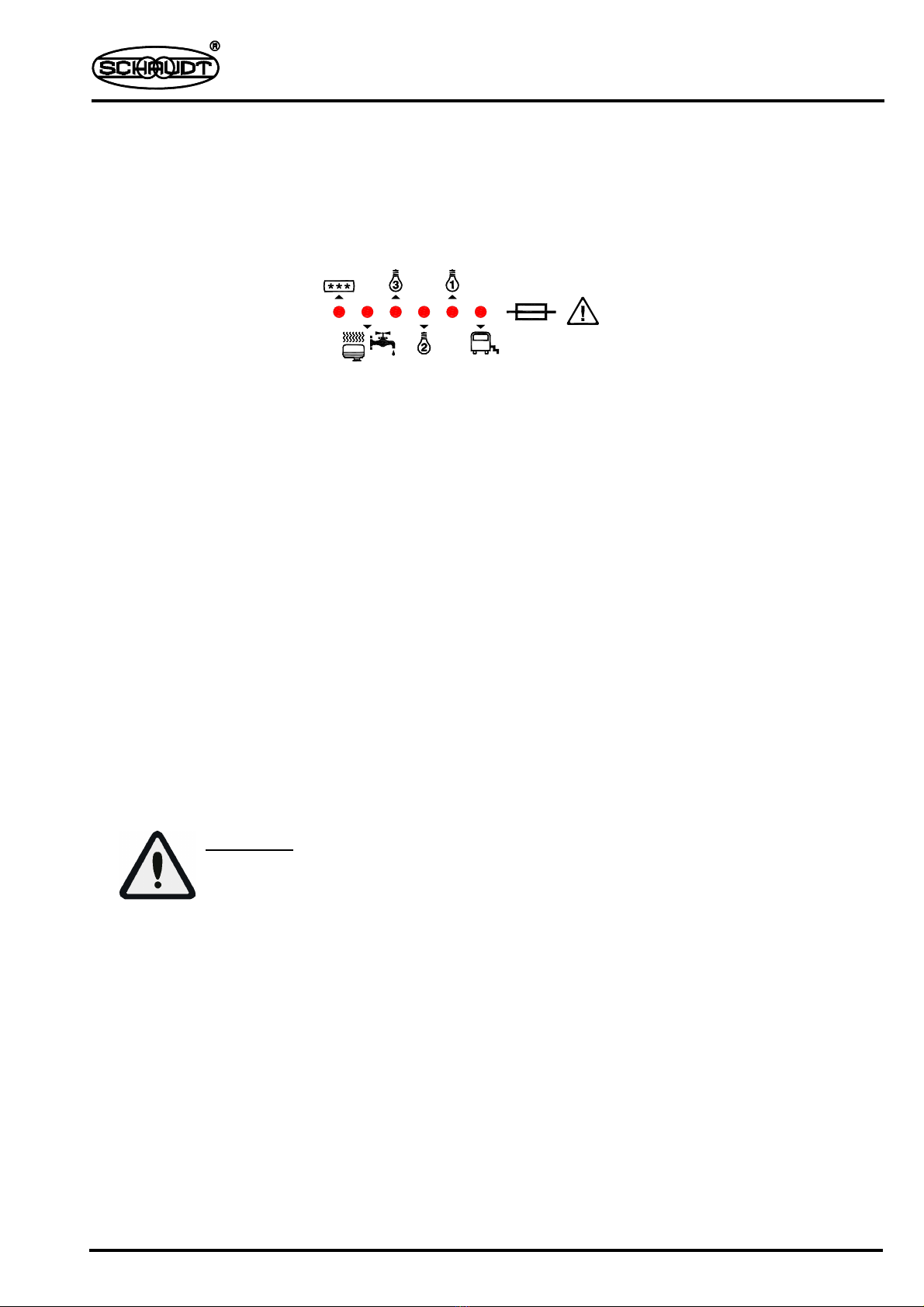
Inquiry of water tank filling levels
LED indication of water tank filling levels in three levels.
Actuate switch in direction of →Filling level of fresh water tank is shown
Actuate switch in direction of →Filling level of waste water tank is shown
LED with symbol is on →water tank full
LED with symbol is on →water tank approx half full
LED with symbol is on →water tank approx a quarter full
No LED indication →water tank empty
Note: Inquiry of water tank filling levels is for temporary use only. The used method of measurement is
not suitable for continuous operation or long inquiries.
Caution !
Continuous operation or long inquiries will damage rod sensors or tank sensors.
Mains supply indicator
The yellow LED indicates that the EBL is connected to 230V
3.2 Additional Features
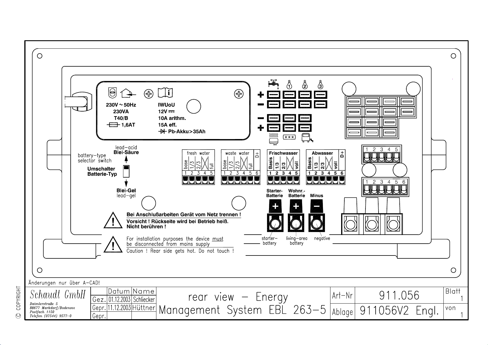
Battery-type selector switch The mains supply of the EBL has to be disconnected prior to actuating
the battery-type selector switch which is situated on the back of the EBL.
This switch has to be set according to the types of batteries used (lead-
acid or lead-gel) before the EBL is put into operation.
The switch ensures an optimum charge of the connected battery type.
To actuate use a thin tool like a ball point pen.
Caution !
An incorrectly set battery-type switch may damage the batteries and there may be an
explosion-hazard caused by detonating gas.
Operating Instruction Manual
Elektroblock EBL 263-5 Art no 911.056 page 6 /10
Note: this operating instruction manual is intended for the customer and has to be supplied with the device
Schaudt GmbH, Elektrotechnik & Apparatebau, Daimlerstraße 5, D-88677 Markdorf, Tel +49 7544 9577-0, Fax +49 7544 9577-29, www.schaudt-gmbh.de 18.05.2004
12V fuses The Elektroblock is equipped with so called PolySwitch fuses.
In case of failure, eg overload, such fuses break the relevant circuit, thus
protecting the device. PolySwitch fuses automatically reset themselves
after the fault has been removed. In case of failure the corresponding LED
lights and indicates the faulty circuit.
The electrical circuits are from left to right:
refrigerator 15 A
waste water heater/
water pump 10 A
light circuit 3 10 A
light circuit 2 10 A
light circuit 1 10 A
automatic step 15 A
* In some cases of short circuit, the main fuse of the starter or the living-area battery might blow instead
of the respective PolySwitch fuse. In this instance please disconnect the mains supply of the motor
home and take off all battery terminals of the positive poles. After that insert a new main fuse of the
same value. Before power is put back on, it is advisable to rectify the reason for the short circuit.
Please see section 5 'Electrical Installation' and in enclosure 'Schematic Diagram'.
* Troubleshooting hints when main fuses are blown (qualified personnel only):
• A minimum of two main fuses are required; for the value refer to schematic diagram.
• Undo the four screws at each corner of the front panel and pull out the device.
• Disconnect all positive poles of each of the seven consumer circuits, label each one well.
• Insert a new main fuse. Caution, danger of burning. Better disconnect the positive battery
terminal first. If the fuse blows again, the main circuit of the battery is at fault, otherwise:
• Actuate 12V-switch on front panel of EBL 263-5: the green LED must light.
• Connect one consumer circuit after the other by reconnecting the appropriate positive poles.
Wait for at least 10sec after each connection is made and observe the green LED.
• The consumer circuit with the green LED going off is at fault.
• Disconnect the appropriate positive pole of the faulty circuit and rubber-tape it against accidental
contact.
• Insert a new main fuse and reconnect all other remaining consumer circuits.
• All other circuits should function now. The faulty circuit should be repaired without delay.
CAUTION !
Danger of burning. Change defective fuses only at zero-current.
3.3 Relay Functions
main-switch relay This relay is controlled by the push-button switch 12V on front panel.
bistable It switches all 12V load off, except the circuit 'automatic step'.
See section 3.1 'Controls and Indicators'.
battery cut-off relay This relay separates the starter and living-area battery when the engine
is not running and if there is no voltage on terminal 'D+'.
Both batteries are connected in parallel and therefore simultaneously
charged while engine is running.
water pump relay This relay activates the water pump and is controlled by the 'water pump'
switch on the front panel. In 'ON' position the 'water pump' output is active.
See section 3.1 'Controls and Indicators'
Battery drain of relay: 160mA in 'ON' position
Operating Instruction Manual
Elektroblock EBL 263-5 Art no 911.056 page 7 /10
Note: this operating instruction manual is intended for the customer and has to be supplied with the device
Schaudt GmbH, Elektrotechnik & Apparatebau, Daimlerstraße 5, D-88677 Markdorf, Tel +49 7544 9577-0, Fax +49 7544 9577-29, www.schaudt-gmbh.de 18.05.2004
refrigerator relay This relay controls the power supply of the absorption-type refrigerator.
The refrigerator is powered by the starter battery but only, when the engine
is running and when there is a voltage on terminal 'D+'.
charging relay This relay automatically provides a 2A trickle-charge to the starter battery
starter battery when the EBL is connected to mains supply.
3.4 Battery Monitor
The battery monitor compares the voltage of the living-area battery with a reference voltage.
As soon as the battery voltage falls below 10.5 V, all 12V load is switched off (except the automatic
step). Short falls (< 2 sec ) below the threshold voltage, due to high inrush currents of connected load,
do not affect the automatic cut-off function.
If the automatic shut-down has been triggered due to overload or an insufficiently charged battery, all
non-essential load should be switched off.
By actuating the 12V push-button switch on the front panel it may be possible to reactivate the 12V-
system for a short period of time.
However, the 12 V system cannot be switched on if the battery voltage stays under 11.0V.
In any case, the living-area battery should be fully recharged as soon as possible.
4. Transport, Storage, Installation
4.1 Transport, Storage
* The EBL should be stored and transported in a suitable packing and in a dry environment only.
* Storage temperature range : - 20°C to + 70°C.
4.2 Installation
* The EBL has been designed for use in a dry and sufficiently ventilated environment within a
temperature range of - 10°C to + 40°C.
* The EBL is designed to be fitted in a cabinet front . A minimum distance of 5 cm to the surrounding
equipment has to be maintained above and to all sides.
In operation a temperature of max. + 40°C in a distance of 2.5 cm has to be maintained.
Caution !
Danger of overheating if distances to equipment are too short or if ventilation is blocked.
* The EBL has to be fitted on a solid and level surface by use of the four provided fixing holes.
It has to be seated on its bottom side without blocking the ventilation.
Please refer to the enclosed table of measures EBL 263-5 for permitted seating details.
5. Electrical Installation
* Electrical installation has to be executed by qualified personnel only.
* The device must be used only with a connected living-area battery.
Caution !
The Elektroblock must not be used without a connected living-area battery, otherwise
connected appliances might be damaged in unfavourable conditions.
* The electrical connection is made on the back according to the enclosed schematic diagram.

Operating Instruction Manual
Elektroblock EBL 263-5 Art no 911.056 page 8 /10
Note: this operating instruction manual is intended for the customer and has to be supplied with the device
Schaudt GmbH, Elektrotechnik & Apparatebau, Daimlerstraße 5, D-88677 Markdorf, Tel +49 7544 9577-0, Fax +49 7544 9577-29, www.schaudt-gmbh.de 18.05.2004
* For installation purposes, the mains plug or the mains supply of the vehicle must be disconnected.
Caution !
Danger of life due to electrical shock or danger of burning with a defective mains
cable, incorrect connection or service with mains supply on.
* Please note: all installation must be carried out with disconnected batteries.
* The electrical connection has to be in accordance to the following sequence:
1. 12V consumers, D+ (alternator) and water-tank connections
2. battery cables at EBL
3. battery cables at battery terminals
4. 230V mains connection
* Disconnection has to be executed vice versa.
5.1 230V Mains Supply
* The mains cable on the back of the device is strain-relieved. Its ends are push-on contacts 6.3 x 0,8.
* Mains supply has to be connected to a insulated earthing-contact junction box.
* The device must be used exclusively in vehicles equipped with an easily accessible cut-out, eg a
circuit breaker in the wardrobe.
5.2 Batteries and D+ (Alternator)
* The battery is connected by a 3-pole EURO terminal.
The alternator control signal D+, is connected to terminal 6 of the 6-pole plug-in screw terminal
('water tank 2, waste water').
* Cable size dimensions have to be in accordance with European norm EN 1648-1 or –2.
* Leads have to be fused according to their cross-sections.
Maximum allowed fuse ratings: Batteries D+ (Alternator)
30A 2A
* The fuses need to be installed close the battery terminals for short circuit protection of the leads
and alternator.
* The negative pole of the living-area battery has to be connected to the negative pole of the starter
battery externally.
Caution !
Danger of burning with incorrect connection and fusing.
* The EBL has to be used exclusively on 12V power systems with rechargeable 6-cell lead-acid or
lead-gel batteries.
Caution !
Unsuitable batteries will be damaged.
* Batteries have to be installed in sufficiently ventilated areas or must have integrated venting.
Please refer to installation instructions of the battery manufacturer.
Caution !
Exploding hazard by detonating gas with defective batteries, defective Elektroblock
or at too high battery temperature (> 30°C).

Operating Instruction Manual
Elektroblock EBL 263-5 Art no 911.056 page 9 /10
Note: this operating instruction manual is intended for the customer and has to be supplied with the device
Schaudt GmbH, Elektrotechnik & Apparatebau, Daimlerstraße 5, D-88677 Markdorf, Tel +49 7544 9577-0, Fax +49 7544 9577-29, www.schaudt-gmbh.de 18.05.2004
5.3 12V Consumers
* 12V consumers are connected by 6,3 x 0,8 push-on plug connectors with insulated housing.
Appropriate insulated counterparts have to be used.
* The choice of cable cross-sections has to comply with EN 1648-1 or –2.
Maximum current drain must not exceed the respective fuse rating.
5.4 Water Tank Connection
* The fresh water and waste water tank are connected by 5-pole and 6-pole plug-in screw terminals.
* Tank cables are sensor leads and do not have to be protected by fuses.
6. To Put Into Operation, Shut-Down, Maintenance
6.1 To Put Into Operation
* The Elektroblock is only fully operational when used with the filling level measurement equipment.
This equipment has to be ordered separately, see section 1.1 'Suitable Accessories'.
* Prior to power-up, special attention must be paid to:
1. living-area battery properly connected
2. correctly selected battery-type selector switch. See section 3.1 'Controls'.
6.2 Shut-Down
* Before and after shut-down (eg winter recess), the battery should be fully recharged.
Connect the motor home to mains supply and charge the battery for a minimum of 16 hours (80Ah
battery) or 24 hours (160Ah battery).
* Before long periods of disuse, the motor home battery should be disconnected from the 12V system.
Take off terminals at battery poles.
Caution !
To prevent battery damage the battery should be fully charged before shut-down of the
vehicle.
6.3 Maintenance
* The Elektroblock EBL 263-5 is maintenance-free.
* For cleaning use a soft moisturized cloth with a mild detergent. Do not use methylated spirit,
paint thinner, etc. Liquids must not be allowed to get into the cabinet.
7. Malfunction
* When being on mains supply the charging module is able to charge flat batteries. For that start the
engine of the motor home for a short while until the battery voltage comes up. Please see section 3.1
'Evaluation of LED battery indicator'. All connected devices must kept switched off until the battery is
at least partly charged.
Caution !
When charging a flat battery, sensitive devices being switched on may get damaged.
* In some cases of short circuit, the main fuse of the living-area battery might blow instead of the
respective PolySwitch fuse. Please see section 3.2 '12V Fuses'.
Caution !
Danger of burning. Change defective fuses only at zero-current.

Operating Instruction Manual
Elektroblock EBL 263-5 Art no 911.056 page 10 /10
Note: this operating instruction manual is intended for the customer and has to be supplied with the device
Schaudt GmbH, Elektrotechnik & Apparatebau, Daimlerstraße 5, D-88677 Markdorf, Tel +49 7544 9577-0, Fax +49 7544 9577-29, www.schaudt-gmbh.de 18.05.2004
* If due to overload the device gets too hot, eg charging an almost empty battery while all load is
switched on, battery charging will automatically be stopped. After cooling down the charging
module activates itself again. However, overheating should in any case be prevented.
* Should repairs be necessary, please contact the service department of Schaudt GmbH,
* If it is not possible to see the manufacturer for service (eg being overseas), necessary repairs can be
carried out by a qualified workshop.
* Unqualified repairs enforce expiration of warranty. The manufacturer Schaudt GmbH disclaims its
liability and is, therefore, not liable to resulting damages.
8. Enclosure
To this operating instruction manual belongs the enclosed schematic diagram, the table of
measurement and front and back view drawings of the Elektroblock EBL 263-5, art no 911.056.
This operating instruction manual with all its enclosures must be delivered together with the energy
management system Elektroblock EBL 263-5, art no 911.056.
It has to be part of the instruction manual if it is part of a system installed in a motor home.
8.1 EC declaration of conformity
We hereby certify that the type of construction of Elektroblock EBL 263-5 complies with appropriate
regulations:
EC low-voltage guide line 73/23/EWG amendment of 22.07.93
Electromagnetic compatibility guide line 89/336/EWG amended to 92/31/EWG
Applied standards and technical specifications,
particularly: DIN VDE 0700 part 1 /11.90 (EN 60335-1:1988)
DIN VDE 0700 part 29 /03.92 (EN 60335-2-29:1991)
DIN VDE 0551 T1 /09.89 (EN 60742:1989)
DIN EN 50081-1:3.1993
DIN EN 50082-1:3.1993
DIN EN 61000-3-2:2000
The EC declaration of conformity in original is available and can be looked at any time.
Manufacturer: Schaudt GmbH, Elektrotechnik & Apparatebau
Address: Daimlerstraße 5
88677 Markdorf
Germany


This manual suits for next models
1
Table of contents
Other Schaudt Power Supply manuals


Popular Power Supply manuals by other brands

Delta Electronics
Delta Electronics PMC-24V150W2AA instruction manual

Manson Engineering Industrial
Manson Engineering Industrial HCS-3400-USB user manual

Altronix
Altronix VertiLine563V installation guide

Pro Audio Eng
Pro Audio Eng PAE-Kx33 owner's manual

Selectronic
Selectronic SP PRO Technical notes

VeriFone
VeriFone UX300 quick start guide


