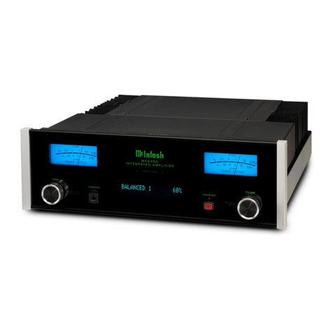
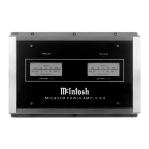
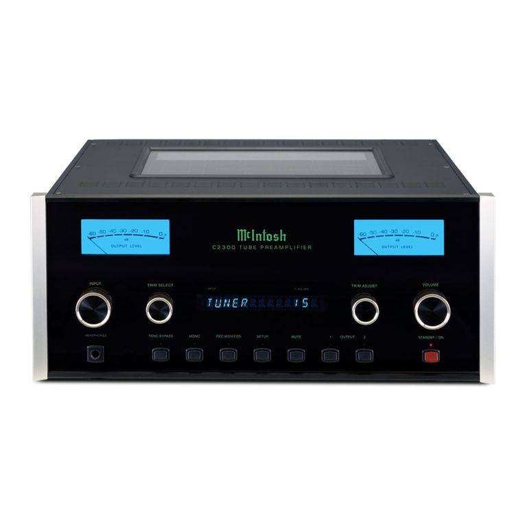
Ordinarymeterslackthecapabilityofindicating
theshortintervalpowerina soundwave.The
massofthemetermovementistoogreattore-
spondtoinstantaneouschangesinmusicpro-
grammaterial.Mclntoshsuperiorengineering
hasdevelopednewcircuitrythatpermitsthe
metersontheMC2505torespondtotheshort
intervalpowerina soundwavetoanaccuracyof
98%ofthetruevalue.ThisisanotherMclntosh
developmentthatrepresentsa majorstepfor-
wardintheuseofpowerlevelmeters.
Therearetwocircuitsthatgivethesemeters
theindicatingcapabilityoftheshortinterval
powerina soundwave.Thefirstcircuitisan
acceleratingcircuitthatcompensatesforthe
inertiacharacteristicsofthemetermovement.
Becausetheshortintervalpowerfluctuationis
sorapid,theeyemightnotperceivetheinstan-
taneouspowerreading.Thiscausedthedevel-
opmentofthesecondcircuit,whichisa "time
stretching"circuit.Thetimestretchingcircuit
delaysthemovementofthemeterneedleat
peakreadingfora fewmilliseconds.
WiththeaidoftheCBStestrecordSTR100,the
frequencyresponseofyourphonocartridgecan
bemeasured.Thegraphonpage5 showsthe
idealRIAAcurveusingtheCBSrecordSTR100.
Followthesestepstoplottheperformanceof
yourphonographcartridge.
1.Setthe"METERRANGESWITCH"tothe
—20
position.
2.Playthe1000Hztesttonerecordedon
theCBSTestRecordSTR100 onyour
phonograph.
3.Turnthe"LEFTGAIN"controluntilthe
leftmeterindicates"0."
4.Turnthe"RIGHTGAIN"controluntilthe
rightmeterindicates"O."
5.Writedownthemeterindicationateach
frequencyastherecordplays.
6.Transferthereadingsbyfrequencyto
thegraph.
7.ThegraphshowstheidealRIAAre-
sponsecurveusingtheCBS#STR100test
record.Compareyourcurvewiththecurve
onthegraph.A deviationof3 dBfromthe
idealisacceptable.Bymakingthischeck
atregularintervals,(forinstance,every6
months)anydeteriorationinthecartridge
orsystemwillbequicklydetected.
DYNAMICPEAK
LOCKINGMETERS
Ataperecordercanbecheckedinthesame
fashion.
1.Usea standardfrequencyresponsetape
asthesignalsource.
2.Completeallstepsoutlinedforphono
cartridges.
3.Younowhavea graphoftheplayback
characteristicsofyourtaperecorder.
Tofindtherecordcharacteristicsofthetape
recorderfollowthisprocedure:
1.RecordtheCBSTestRecord#STR100
onyourtaperecorder.Adjusttherecord
volumeonlyonthe1000Hzsignalfor
properrecordinglevel.DONOTADJUST
THERECORDVOLUMECONTROLDUR-
INGTHERECORDING.
2.Playbackthetapejustrecorded.Com-
pleteallstepsoutlinedfortapeplayback
characteristics.
3.A comparisonofthetwocurveswillgive
therecordingcharacteristicsofyourtape
recorder.A deviationof3 dBisacceptable.
Similarcheckscanbemadeonallprogram
sourcesinyourstereosystem.Followthesame
generalprocedureforanyprogramsourcefor
whicha standardreferenceisavailable.
•1
