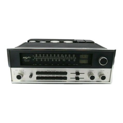
McIntosh MAC1500 - SERVICE 1 User manual

MAC1500STEREORECEIVERWARRANTYSTATION
SERVICEMANUAL
CONTENTS
McINTOSHAUDIOCOMPANY
2
ChambersSt., Binghamton,N.Y.
13903
MAC1500
INTRODUCTION1
FMALIGNMENTCHART2-3
MULTIPLEXDECODERALIGNMENTCHART_ 4-5
SCHEMATIC6-7
TESTSANDADJUSTMENTS8
DIALSTRINGING8
PARTSLIST9-14
TOPANDBOTTOMVIEWS15
SPECIFICATIONS16
BLOCKDIAGRAM16

MAC1500STEREORECEIVER
INTRODUCTION
AllMclntoshtunersarecarefullyalignedandtestedatthefactoryusingthefinest
availabletestequipment.AllMclntoshtunerswillmeettheirpublishedspecifica-
tionswhenshippedfromthefactory.
Afterextensiveoperation,especiallywhentubeshavebeenreplaced,itmaybe
desirabletorealignthetimercircuitsforbestperformance.Thismanualgives
completeinformationonthecircuitrealignmentprocedurefortheMAC1500
receiver.
Thetestequipmentlistedbelow(oritsequivalent)isnecessarytoproperly
aligna MAC1500.Theaccuracyofthealignmentwillbedirectlyrelatedtothe
accuracyandcalibrationofthetestequipmentused.
FMSignalGenerator(Measurements210Aorequivalent)
VTVM
MultiplexGenerator(RCAWR51Aorequivalent)
10.7MCGenerator(Preferablycrystalcontrolled)
Oscilloscope(Hewlett-Packard120Borequivalent)
HarmonicDistortionAnalyzer(Hewlett-Packard330Borequivalent)
Ifthenecessarytestequipmentisnotavailable,alignmentshouldnotbe
attempted.YoumaycontacttheMclntoshCustomerServiceDepartmentfor
additionalinformation.
CustomerService
MclntoshLaboratory,Inc.
2ChambersStreet
Binghamton,NewYork
Ourtelephonenumberis723-5491
Thedirectdialareacodeis607
1

MAC
1500
STEPS
1
2
3
4
5
6
7
8
9
10
11
2
TUNER
DIAL
SETTING
Pointofno
interference
andnosignal
SAME
SAME
105MC
90MC
105MC
90MC
90MC
105MC
and
90MC
90MC
90MC
SIGNALGENERATOR
FREQ.
10.7MC
SAME
SAME
105MC
90MC
105MC
90MC
90MC
105MC
and
90MC
90MC
90MC
COUPLING
Throughexternal
.01MFDcapacitor
tomixergrid(pin
4or6DS4,V2)
SAME
SAME
300ohmantenna
terminalswith
matchingnetwork*
SAME
SAME
SAME
SAME
SAME
SAME
SAME
MODULATION
cw
SAME
SAME
400cycles
75KCdeviation
(100%modulation)
SAME
SAME
SAME
SAME
50cps150KC
deviationApprox.
5microvoltsat
antennaterminals
400cycles
75KCdeviation
(100%modulation)
SAME
INDICATOR
TYPE
VTVM
SAME
SAME
CONNECTED
TO
TP#1
Pin1 ofT4
TP#2
VTVMconnectedtoTP#2and.
scopeconnected
toLorR
tape
output
SAME
SAME
SAME
VTVMconnectedtoTP#2;
scopeanddistortionanalyzer
connectedtoL orR tape
output
Seenote**atbottomofpage
ScopeconnectedtoL orR
tapeoutput
VTVMconnectedtoTP#1;
scopeanddistortionanalyzer
connectedtoL orR tape
output

FMALIGNMENT
ADJUST
Top(secondary)
andbottom
(primary)of
T1.T2,T3
Primaryand
secondaryof
T4
Secondary
(top)
of
T-5
-4
L-4
C-2,
C-3
L-1,L-2,
L3
Primary(bottom)
ofT-5
L-2,
C-3
Mutingthreshold
control
TEST
LIMITS
Maximumpos-
siblenegative
voltage
Maximumpos-
siblenegative
voltage(should
be20to30
volts)
Adjustfor0 volts
Maximumnega-
tivevoltage
SAME
SAME
SAME
0.5%distortion
orless
Minimumtilt
IHFMSensitivity
2.5microvolts
for3%total
noiseand
distortion
REMARKS
Beforemakinganyadjustments,setthecontrolsasfollows:
a)InputselectorswitchtoFMmono,
b)VolumecontrolmaximumCCW.
c)MutingpotmaximumCW.
d)MutingOUT.
e)StereolightadjustmaximumCW.
Shunttogroundthewindingnotbeingadjusted.Dothiswitha .01
MFDcapacitorinserieswitha 1Kresistor.Attenuatesignalgenerator
untiloutputvoltageatTP#1islessthan1.5voltswithoneIFtrans-
formerwindingshunted.IFtransformershaveterminal#1marked
witha greendotandarenumberedclockwise.
_
Mutingpot.MUSTbemaximumCW.
Theprimary(bottom)ofT-5shouldbeadjustedonlyifa distortion
analyzerisavailable.
Repeatsteps4 and5 untildialcalibrationisaccurate.
Asoutputincreases,attenuatesignalgeneratortokeepmaximumout-
putatTP#1tolessthan1 volt.
Repeatsteps6 and7 untiloutputisashighaspossible.
Usea strongsignalfromtheFMgenerator.AdjustT-5primaryfor
minimumdistortion.IFA DISTORTIONANALYZERISNOTAVAILABLE,
OMITTHISSTEP.DONOTADJUSTT-5PRIMARY.
Observedirectionoftiltofoverallresponsecurveat105MCand90MC.
If
direction
isthe
same,
adjust
L-2at
100MC
for
minimum
tilt.
Re-check
tilt
at
90MC
and
105MC.
If
direction
isnotthe
same,adjust
L-2(at
90MC)
andL-3(at
105MC)
for
minimum
tilt.
Check
tilt
again
at
100MC.
WithFMgeneratorsetfor2.5microvoltsoutput,placemutingcontrol
to"IN."Adjustthemutingthresholdcontroltothepointatwhichthe
sinewaveonthescopebecomeserratic.
Step11isanoverallsensitivitycheck.Itrequiresa distortionanalyzer
andFMsignalgeneratorwithattenuator.With2.5microvoltsinputat
the300ohmterminals,TP#1voltageshouldbe.45voltsormore.
3

MAC1500MULTIPLEX
STEPS
1
2
3
4
5
6
7
8
TUNER
DIAL
SETTING
Pointofno
interference
orsignal
SAME
100MC
SAME
SAME
SAME
SAME
SAME
SIGNALGENERATOR
FREQ.
Audiogener-
atorsetto67KC
0.5voltsout-
putorless
MPXgenerator
with19KCpilot
attenuatedto
approx.5%
level.(5%level
is½ ofnormal
10%level).
19KCpilot
MUSTbeat-
tenuatedfor
correctalign-
ment
100MCmodu-
latedbyMPX
generator.
19KCpilotat
normaloutput
SAME
SAME
SAME
SAME
Tunetoa strong
monoFM
station
COUPLING
TP#2
SAME
300ohm
antennatermi-
nalswith
matchingnet-
work.(See*
previouspage)
SAME
SAME
SAME
SAME
SAME
MODULATION
1KC100%modu-
lation
(34KC
deviation)modu-
latingleftor
rightonly
SAME
SAME
SAME
Turnoff1KCaudio
modulation
INDICATOR
TYPE
Audio
VTVM
DC
VTVM
Audio
VTVM
Audio
VTVM
and
scope
SAME
SAME
SAME
MPX
stereo
indi-
cator
lighton
receiver
CONNECTED
TO
LorR tapeoutput
Pin9 of6EA8
Pin1 or2 ofT-7
LorR tapeoutput
SAME
SAME
SAME
4

DECODERALIGNMENT
ADJUST
67KCTrap(L-6)
T-6topand
bottom;
L-5
T-7bottomcore
T-7topcore
L-5
MPXlightadjust
controlR-12
TEST
LIMITS
Adjustformini-
mumvoltage
Adjustformaxi-
mumvoltage
SAME
Adjustforstable
scopedisplay
30dbseparation
ormore
SAME
REMARKS
Stereolightmustbeon.Thisisdonebyadjustingthe"MPXLight
control,R-12.
Adj."
Stereolightmustbeoff.
•~
Stereolightmustbecompletelyon.
1.Turnoff19KCpilotonMPXgenerator.
2.AdjustuppercoreofT-7toobtaina stableanduniform1 KCsignal
scopedisplay.Thisadjustmentmaybecritical,soturncorevery
slowly.
3.Turn19KCpilotbackon.
Modulateleftchannelandmeasurerightchanneloutput.AdjustL-5for
minimumrightchanneloutput(maximumseparation).Besurealltest
leadsareremovedfromTP#2forseparationtests.
Modulaterightchannelandmeasureleftchanneloutput.Separationin
steps5 and6 shouldbeatleast30db.
Thisstepcheckstherejectionof19KCand38KCfrequencies.Residualoutputshouldbe
atleast40dbbelowmodulatedoutput.
Turncontroluntillightcomeson.Thenbackoffjustenoughtocause
thelighttogooff.Thenbackoffabout1/8ofa turnmore.Lightshould
operateONLYona MPXsignal.
5

6

7

PREAMP/AMP
TESTSANDADJUSTMENTS
Alladjustmentsshouldbemadeaftera minimumofa
10minutewarm-up.
1Removethe12AX7(V-9).
2MeasurethevoltageatTP#3.Voltageshould
be0.7voltspositive.Ifitisnot0.7volts,ad-
justR-8.
3DolikewisewithTP#4andR-9,TP#5and
R-10,TP#6andR-11.
4Re-insertthe12AX7.
5Feeda 1 KCsignalintoAUX.Drivetheampto
full30wattsoutput.Besureallcontrolsare
setfora flatresponse.Checktobesurethe
channelshaveequaloutputwithequaldrive
fromtheaudiooscillator.Ifchannelsareun-
balanced,adjustR-55,Thiscontrolisfoundon
the
leftpreampprintedcircuitboard.
It
will
varytheoutputoftheleftchannel.Thepreamp
covermustberemovedtogainaccesstothis
control.
6Measureharmonicdistortionat30cycles.Ad-
justR-6forminimumdistortionontheleft
channelandR-7fortheright.Distortionmust
belessthan0.5%.Thebottomcovermustbe
removedtoadjustthesecontrols.Theyhave
blueplasticknobs.
7Nowmeasuredistortionat2KCand20KC.
Mustbelessthan0.5%atfulloutput.
8Next,feeda signalthruthephonoinputs.
CheckforcorrectRIAAequalization.
9Removeallinputs.Checkhumandnoiseon
phono1.Shouldbeatleast60dbbelowrated
output.
DIALSTRINGING
8

MAC1500PARTSLIST
TUBES
ITEM
NO.
V-1
V-2
V-3
V-4
V-5
V-6
V-7
v-8
V-9
V-10
V-11
V-12
V-13
V-14
V-15
ITEM
NO.
Q-1
Q-2
0-3
Q-4
Q-5
Q-6
Q-7
Q-8
Q-9
Q-10
Q-11
Q-12
Q-13
Q-14
Q-15
0-16
Q-17
Q-18
Q-19
Q-20
ITEM
NO.
D-1
D-2
D-3
D-4
D-5
D-6
0-7
D-8
D-9
D-10
D-11
D-12
D-13
D-14
D-15
D-16
USE
HF
Amplifier
Mixer
1stIFAmplifier
2ndIFAmplifier
3rdIFAmplifier,1stLimiter
4thIFAmplifier,2ndLimiter
19KCAmplifier,IndicatorControl
MPX38KCOscillator
VoltageAmplifier
LeftChannelDriver
RightChannelDriver
LeftChannelOutput
LeftChannelOutput
RightChannelOutput
RightChannelOutput
TRANSISTORS
USE
LocalOscillator
ControlAmplifier
MPXLampControl
OscillatorOn-QffControl
LeftChannelAudioAmplifier
RightChannelAudioAmplifier
LeftChannelAudioAmplifier
RightChannelAudioAmplifier
LeftChannelLowLevelAmplifier
RightChannelLowLevelAmplifier
LeftChannelEmitterFollower
RightChannelEmitterFollower
LeftChannelLowLevelAmplifier
RightChannelLowLevelAmplifier
LeftChannelEmitterFollower
RightChannelEmitterFollower
LeftChannelEmitterFollower
RightChannelEmitterFollower
LeftChannelVoltageAmplifier
RightChannelVoltageAmplifier
DIODES
DESCRIPTION
Diode
Diode
Diode
Diode
Diode
Diode[Matchedpair1N542)
Diode(Matchedpair1N542)
Diode(Matchedpair1N542]
800PIV@ 750MASiliconRectifier
600PIV@ 750MASiliconRectifier
800PIV@ 750MASiliconRectifier
400PIV@ 750MASiliconRectifier
10V @ 400MWZenerRectifier
TUBE
NUMBER
6DS4
6DS4
6AU6
6AU6
6AU6
6CS6
6EA8
12AU7
12AX7
12AU7
12AU7
7591
7591
7591
7591
TRANSISTOR
NUMBER
TA2556/40244
2N3638
2N3391A
2N3391A
2N3391A
2N3391A
2N3391A
2N3391A
2N3391A
2N3391A
2N3391A
2N720A
2N720A
2N339IA
2N3391A
2N3391A
2N3391A
2N720A
2N720A
DIODE
NUMBER
FD100
FD100
FD100
FD100
FD100
IN542
1N542
1N543
IN542
PART
NUMBER
165-013
165-013
165-004
165-004
1
65-004
165-011
1
65-044
165-018
165-019
165-018
165-018
165-022
165-022
1
65-022
165-022
PART
NUMBER
1
32-008
132-007
132-010
132-004
132-004
132-004
1
32-004
132-004
132-004
132-004
132-004
132-004
1
32-002
132-002
1
32-004
132-004
132-004
132-004
132-002
1
32-002
PART
NUMBER
070-022
070-022
070-022
070-022
070-022
070-003
070-003
070-003
070-003
070-003
070-017
070-016
070-016
070-017
070-015
070-011
9

CONTROLS
ITEM
NO.
R-1
R-2
R-3
R-4
R-5
R-6
R-7
R-8
R-9
R-10
R-11
R-12
R-55
FUNCTION
BalanceControl
BassControl
TrebleControl
VolumeControl
MutingAdjustControl
DriverBalanceControl
BiasAdjustControl
BiasAdjustControl
BiasAdjustControl
BiasAdjustControl
MPXLightAdjustControl
LeftChannelGainControl
RESISTANCE
500K-500K
IM-1M
500K-500K
60K-60K
100K
5K
5K
100K
100K
100K
100K
100K
5K
PART
NUMBER
134-165
134-117
134-118
134-164
134-102
134-103
134-103
134-102
134-102
134-102
134-102
134-102
134-120
SWITCHES
ITEM
NO.
S-1
FUNCTION
RotarySwitch
SS-2619/32TriggerSlideSwitch
SS-507/32TriggerSlideSwitch
SS-5019/32TriggerSlideSwitch(Sused)
DESCRIPTION
InputSelector
Muting
On
-Off
SpeakerOn-Off
Stereo/Mono,TapeMonitor,
LFandHFFillers,Loudness.
PART
NUMBER
146-096
148-003
148-006
1
48-007
TRANSFORMERS
ITEM
NO.
T-1
T-2
T-3
T-4
T-5
T-6
T-7
T-8
T-9
T-10
Ml
FUNCTION
FM-IF
FM-IF
FM-IF
IF(Muting)
FMDiscriminator
19KCAmplifier
38KCOscillator
Balun
Output(Left)
Output(Right)
Power
PART
NUMBER
162-005
162-004
162-004
162-029
1
62-027
162-010
162-009
076-006
159-062
159-062
159-061
CAPACITORS
10
ITEM
NO.
C-1
C-2
C-3
C-4
C-5
C-6
C-7
C-8
C-9
C-10
C-11
C-13
C-16
C-17
C-18
C-19
C-20
C-21
C-22
C-23
C-24
C-27
C-28
C-29
C-30
DESCRIPTION
VariableFM
Trimmer(Ceramic)
Trimmer(Ceramic)
Trimmer(Glass)
CeramicDisc.
CeramicDisc.
CeramicDisc.
CeramicFeed-Thru
CeramicFeed-Thru
CeramicDisc.
CeramicTubular
CeramicDisc.
CeramicDisc.
CeramicTubular
CeramicDisc.
CeramicFeed-Thru
CeramicFeed-Thru
CeramicFeed-Thru
CeramicDisc.
CeramicDisc.
CeramicDisc.
CeramicFeed-Thru
CeramicFeed-Thru
CeramicDisc.
CeramicDisc.
CAPACITANCE
1-8PF
1-8PF
.005MFD
.001
MFD
.001
MFD
..001MFD
.001MFD
10PF
5PF
.005
10PF
3PF
10PF
.001
MFD
.001MFD
.001
MFD
..005MFD
10PF
.005
MFD
.001
MFD
.001MFD
.005MFD
.01
MFD
TOLERANCE
+80-20%
20%NPO
±.25PF
N150
+80-20%
20%NPO
±.25PF
20%NPO
+80—20%
20%NPO
+80-20%
+80-20%
+80-20%
PART
NUMBER
059-006
060-001
060-001
060-002
061-040
061-035
061-035
061-036
061-036
061-009
061-005
061-040
061-009
061-003
061-009
061-036
061-036
061-036
061-040
061-009
061-040
061-036
061-036
061-040
061-043

CAPACITORS
HEM
NO.
C-31
C-32
C-33
C-34
C-35
C-36
C-37
C-38
C-40
C-41
C-42
C-43
C-44
C-45
C-46
C-47
C-48
C-49
C-50
C-51
C-52
C-53
C-54
C-55
C-56
C-57
C-58
C-59
C-60
C-61
C-62
C-63
C-64
C-65
C-66
C-67
C-68
C-69
C-70
C-71
C-72
C-73
C-74
C-75
C-76
C-77
C-7B
C-79
C-80
C-81
C-82
C-83
C-84
C-85
C-86
C-87
C-88
C-89
C-90
C-91
C-92
C-93
C-94
C-95
C-96
C-97
C-98
C-99
C-100
C-101
C-102
C-103
C-104
C-105
C-106
C-107
C-108
C-109
C-110
C-111
C-112
C-113
DESCRIPTION
CeramicDisc.
CeramicDisc.
CeramicDisc.
CeramicDisc.
CeramicDisc.
CeramicTubular
FlatFoil
CeramicFeed-Thru
CeramicFeed-Thru
CeramicFeed-Thru
CeramicFeed-Thru
CeramicDisc.
CeramicDisc.
CeramicDisc.
CeramicDisc.
CeramicDisc.
CeramicDisc.
CeramicFeed-Thru
CeramicDisc.
SilverMica
CeramicDisc.
CeramicDisc,
CeramicDisc.
CeramicDisc.
SilverMica
SilverMica
Electrolytic
CeramicDisc.
CeramicDisc.
SilverMica
SilverMica
CeramicDisc.
CeramicDisc.
CeramicDisc.
CeramicDisc.
CeramicDisc.
CeramicDisc.
CeramicTubular
CeramicTubular
CeramicDisc.
CeramicDisc.
FlatFoil
FlatFoil
CeramicDisc.
FlatFoil
FlatFoil
CeramicDisc.
CeramicDisc.
Electrolytic
Electrolytic
CeramicDisc.
CeramicDisc.
CeramicDisc.
CeramicDisc.
CeramicTubular
CeramicTubular
FlatFoil
FlatFoil
FlatFoil
FlatFoil
MoldedFilm
MoldedFilm
Electrolytic
Electrolytic
Mylar
Mylar
CeramicDisc.
CeramicDisc.
FlatFoil
FlatFoil
Electrolytic
Electrolytic
CeramicDisc.
CeramicDisc.
Mylar
Mylar
Mylar
Mylar
Mylar
Mylar
CeramicTubular
CeramicTubular
CAPACITANCE
12PF
.1MPD
.005MFD
.005MFD
.01MFD
15PF
.1MFD
.001
MFD
.001
MFD
.001
MFD
.001
MFD
.1MFD
.005MFD
.005MFD
6.8PF
12PF
47PF
100PF
.02MFD
.0027MFD
100PF
.001MFD
.001MFD
.02MFD
.0012MFD
.0012MFD
100MFD
_1MFD
220PF
.0047MFD
.0047MFD
.005MFD
.005MFD
.005MFD
.005MFD
330PF
330PF
430PF
430PF
.01MFD
.01
MFD
.22MFD
.22MFP
10PF
.22MFD
.22MFD
.1MFD
.1MFD
100MFD
100MFD
.1MFD
.1MFD
.0012MFD
.0012MFD
430PF
430PF
.22MFD
.22MFD
.22MFD
.22MFD
.22MFD
.22MFD
100MFD
100MFD
.47MFD
.7MFD
.0015
MFD
.0015MFD
.047MFD
.047MFD
100MFD
100MFO
47PF
47PF
.25MFD
.25MFD
.1MFD
.1MFD
.1MFD
.1MFD
430
PF
430PF
VOLTAGE
40V
100V
100V
100V
3V
40V
40V
40V
40V
12V
12V
40V
40V
40V
40V
200V
200V
12V
12V
100V
10CV
40V
40V
3V
3V
400V
400V
600V
600V
600V
600V
TOLERANCE
20%NPO
+80-20%
+80-20%
+80—20%
+80-20%
±.75PF
N150
20%
+80-20%
+80-20%
+80-20%
20%NPO
20%NPO
20%N470
20%
+80-20%
5%
10%N1500
+80-20%
5%
5%
+80-20%
20%
5%
5%
+80-20%
+80-20%
+80—20%
+80-20%
10%
10%
5%
5%
+80—20%
+80-20%
20%
20%
20%NPO
20%
20%
+80-20%
+80-20%
+80-20%
+80-20%
10%
10%
5%
5%
20%
20%
20%
20%
20%
20%
10%
10%
10%
10%
20%
20%
20%N470
20%N470
10%
10%
10%
10%
10%
10%
5%
5%
PART
NUMBER
061-010
061-049
061-040
061-040
061-043
061-012
064-027
061-036
061-036
061-036
061-036
061-049
061-040
061-040
061-008
061-010
061-019
061-021
061-045
063-004
061-023
061-035
061-035
061-045
063-002
061-002
066-047
061-049
061-028
063-005
063-005
061-040
061-040
061-040
061-040
061-029
061-029
061-031
061-031
061-043
061-043
064-024
064-024
061-009
064-024
064-024
061-049
061-049
066-018
066-018
061-049
061-049
061-051
061-051
061-031
061-031
064-024
064-024
064-024
064-024
064-013
064-013
066-018
066-018
064-019
064-019
061-038
061-038
064-036
064-036
066-047
066-047
061-019
061-019
064-016
064-016
064-012
064-012
064-012
064-012
061-031
061-031
11

CAPACITORS
ITEM
NO,
C-114
C-115
C-116
C-117
C-118
C-119
C-120
C-121
C-122
C-123
C-124
C-125
C-126
C-127
C-128
C-129
C-130
C-131
C-132
C-133
C-134
C-135
ITEM
NO.
L-1
L-2
L-3
L-4
L-5
L-6
L-7
L-8
L-9
L-10
L-11
L-12
L-13
L-14
L-15
L-16
L-17
L-16
L-19
L-20
L-21
DESCRIPTIONCAPACITANCE
Mylar
Mylar
CeramicDisc.
CeramicDisc.
Mylar
Electrolytic
Electrolytic
Tubular
Tubular
Tubular
Electrolytic
CeramicDisc.
CeramicFeed-Thru
CeramicDisc.
FixedComposition
FixedComposition
CeramicTubular
CeramicDisc.
CeramicTubular
CeramicDisc.
CeramicDisc.
CeramicDisc.
DESCRIPTION
AntennaCoil
R.F.Coil
MixerCoil
OSC.Coil
PeakingCoil
FilterCoil
.1MFD
.1MFD
.005MFD
.005MFD
.47MFD
60-40MFD
40-40-40MFD
50MFD
100MFD
50MFD
50-50-50-
50MFD
.001
MFD
.001
MFD
.005MFD
.18PF
.18PF
430PF
.02MFD
5PF
1SOPF
150PF
4.7PF
COILS
NeutralizingChoke
ParasiticChoke
RFChoke
RFChoke
RFChoke
RF
Choke
RFChoke
RFChoke
RFChoke
RFChoke
RFChoke
RFChoke
PeakingCoil
FilterCoil
FillerCoil
VOLTAGE
125V
125V
1400V
1400V
200V
500V-500V
450V-300V-150V
50V
12V
50V
200V-200V-
200V-200V
VALUE
19KC
67KCTrap
2.5MicroH
1.2MicroH
1.2MicroH
1.2MicroH
1.2MicroH
1.2MicroH
1.2MicroH
1.2MicroH
1.2MicroH
1.2MicroH
75MicroH
38MicroH
LoPass
LoPass
TOLERANCE
10%
10%
10%
+80-20%
10%
10%
5%
+80-20%
±.25PF
N220
20%
20%
20%NPO
3%
PART
NUMBER
064-028
064-028
061-052
061-052
064-020
066-026
066-032
066-014
066-018
066-014
066-036
061-035
061-036
061-040
069-001
069-001
061-031
061-045
061-007
061-025
061-025
061-004
PART
NUMBER
122-035
122-054
1
22-055
1
22-056
122-008
122-009
122-033
122-028
122-011
122-011
122-011
122-011
122-011
122-011
122-011
122-011
122-011
122-013
122-014
122-015
122-015
RESISTORS
ITEM
NO.
R-13
R-14
R-15
R-16
R-17
R-16
R-19
R-20
R-21
R-22
R-23
R-24
R-25
R-26
R-27
R-2S
R-29
R-30
R-31
R-32
R-33
R-34
R-35
RESISTANCE
47K
100ohms
15K
3.3K
220ohms
1K
470K
1M
100ohms
1K
100ohms
10K
10M
47K
470K
100K
1K
6.8K
220K
470K
47K
470K
2.2K
TOLERANCE
10%
10%
10%
10%
10%
10%
10%
10%
10%
10%
10%
10%
10%
10%
10%
10%
10%
10%
10%
10%
10%
10%
10%
WATTAGE
¼W
½w
¼W
¼W
¼W
½W
¼W
½W
½W
½W
½W
½W
½W
¼W
¼W
½W
½W
½W
¼W
¼W
½W
¼W
½W
PART
NUMBER
136-339
136-068
136-377
136-385
136-396
136-110
136-373
136-236
136-068
136-110
136-068
136-152
136-278
136-339
136-222
136-301
136-110
136-145
136-372
136-373
136-180
136-373
136-124
12

RESISTORS
ITEM
NO.
R-36
R-37
R-38
R-39
R-40
H-41
R-42
R-43
R-44
R-45
R-46
R-47
R-48
R-49
R-50
R-S1
R-52
R-53
R-54
R-60
R-61
R-62
R-63
R-64
R-65
R-66
R-67
R-68
R-69
R-70
R-71
R-72
R-73
R-74
R-75
R-76
R-77
R-78
R-79
R-80
R-81
R-82
R-83
R-84
R-85
R-86
R-87
R-88
R-89
R-90
R-91
R-92
R-93
H-94
R-95
R-96
R-97
R-98
R-99
R-100
R-101
R-102
R-103
R-104
R-105
R-106
R-107
R-108
R-109
R-110
R-111
R-112
R-113
R-114
R-115
R-116
R-117
R-118
R-119
R-120
R-121
R-122
R-123
RESISTANCE
220ohms
10K
10K
22K
39K
2.2K
IK
1M
470ohms
4.7K
2.7K
1M
1M
1M
4.7K
1.2K
1K
4.7K
100K
220K
100K
6.8K
22K
47K
47K
47K
47K
150K
150K
1M
1M
4.7M
4.7M
6.8K
6.8K
1.8K
I.8K
470K
470K
1M
1M
4.7M
4.7M
1K
1K
1M
1M
1.2K
1.2K
100K
100K
27K
27K
220K
220K
680ohms
630ohms
15K
15K
3.3M
3.3M
I30K
180K
47K
47K
22K
47K
22K
47K
47K
47K
1M
1M
1M
1M
27K
27K
100K
100K
470K
470K
18K
18K
TOLERANCE
10%
10%
10%
10%
10%
10%
10%
10%
10%
10%
10%
10%
10%
10%
10%
10%
10%
10%
J0%
10%
10%
10%
10%
10%
10%
10%
10%
5%
5%
10%
10%
10%
10%
10%
10%
10%
10%
10%
10%
10%
10%
10%
10%
10%
10%
10%
10%
5%
5%
10%
10%
10%
10%
10%
10%
10%
10%
10%
10%
10%
10%
5%
5%
10%
10%
10%
10%
10%
10%
5%
5%
10%
10%
10%
10%
10%
10%
10%
10%
10%
10%
10%
10%
WATTAGE
½W
¼W
¼W
½W
¼W
¼W
½W
¼W
¼W
¼W
¼W
¼W
¼W
½W
¼W
½W
¼W
¼W
¼W
¼W
¼W
½W
¼W
¼W
¼W
¼W
¼W
¼W
¼W
¼W
¼W
¼W
¼W
¼W
¼W
¼W
¼W
¼W
¼W
¼W
¼W
¼W
¼W
¼W
¼W
¼W
¼W
¼W
¼W
¼W
¼W
¼W
¼W
¼W
¼W
¼W
¼W
¼W
¼W
¼W
¼W
¼W
¼W
¼W
¼W
¼W
¼W
¼W
¼W
¼W
¼W
¼W
¼W
¼W
¼W
¼W
¼W
¼W
¼W
¼W
¼W
¼W
¼W
PART
NUMBER
136-082
136-382
136-382
136-166
136-370
136-367
136-110
136-303
136-295
136-298
136-297
136-303
136-303
136-236
136-298
136-114
1
36-296
136-298
136-301
136-372
136-301
136-145
136-369
136-339
136-339
136-339
136-339
136-371
136-371
136-303
136-303
136-374
136-374
136-368
136-368
136-381
136-381
136-373
136-373
136-303
136-303
136-374
136-374
136-296
136-296
136-303
136-303
1
36-394
136-394
136-301
136-301
136-379
136-379
136-372
136-372
136-378
136-378
136-377
136-377
136-380
136-380
1
36-387
136-387
136-339
136-339
136-369
136-339
136-369
136-339
136-388
136-388
136-303
136-303
136-303
136-303
136-379
136-379
136-301
136-301
136-373
136-373
136-386
136-386
13

RESISTORS
ITEM
NO.
R-124
R-125
R-126
R-127
R-128
R-129
R-130
H-131
R-132
R-133
R-134
R-135
R-136
R-137
R-J3S
R-139
R-140
R-141
R-142
R-143
R-144
R-145
R-146
R-147
R-148
R-149
R-150
R-151
R-152
R-153
R-151
R-155
R-156
R-157
R-158
R-159
R-160
R-161
R-162
R-163
R-164
R-165
R-166
R-167
R-168
R-169
R-170
R-171
R-172
R-173
R-174
R-175
R-176
R-177
R-178
R-179
R-180
MSI
R-182
R-183
R-184
R-185
R-186
R-187
R-188
R-189
R-190
R-191
RESISTANCE
7.5K
4.7K
7.5K
4.7K
150ohms
150ohms
5.6K
5.6K
3.3K
3.3K
100ohms
100ohms
330K
330K
15K
15K
1.2M
1.2M
18K
18K
27K
27K
30K
30K
220K
220K
220K
220K
22K
4.7K
4.7K
4.7K
4.7K
15ohms
15ohms
15ohms
15ohms
1.8K
1.8K
47ohms
47ohms
2.2M
900ohms
3.6K
33K
33K
6K
6K
8.2K
18K
220ohms
220ohms
220ohms
1.5K
1M
1M
1K
1K
470K
27K
27K
1M
1M
1K
10K
100ohms
1K
470K
TOLERANCE
5%
10%
5%
10%
10%
10%
5%
5%
10%
10%
5%
5%
10%
10%
10%
10%
10%
10%
10%
10%
10%
10%
5%
5%
10%
10%
10%
10%
10%
10%
10%
10%
10%
5%
5%
5%
5%
5%
5%
20%
20%
10%
10%
10%
10%
10%
10%
10%
10%
10%
10%
10%
10%
20%
10%
10%
10%
10%
10%
10%
10%
10%
10%
10%
10%
10%
10%
10%
WATTAGE
¼W
¼W
¼W
¼W
¼W
¼W
¼W
¼W
½W
½W
½W
½W
½W
½W
½W
½W
½W
½W
1W
1W
1W
1W
1W
1W
¼W
¼W
¼W
¼W
½W
½W
½W
½W
½W
1W
1W
1W
1W
½W
½W
2W
2W
½W
5W
5W
½W
½W
5W
5W
1W
½W
5W
5W
5W
2W
¼W
¼W
½W
½W
½W
¼W
¼W
¼W
¼W
½W
¼W
½W
¼W
¼W
PART
NUMBER
136-376
136-298
136-376
1
36-298
136-294
136-294
136-397
136-397
136-131
136-131
136-067
136-067
136-215
136-215
136-159
136-159
136-240
1
36-240
136-313
136-313
136-316
136-316
136-317
136-317
1
36-372
136-372
136-372
136-372
136-166
136-138
136-138
136-138
136-138
1
39-034
1
39-034
139-034
139-034
136-120
136-120
136-323
136-323
136-250
139-012
139-013
136-173
136-173
139-033
139-033
136-311
136-163
1
39-009
139-009
139-009
136-329
136-303
136-303
136-110
136-110
136-222
136-379
136-379
136-303
136-303
136-110
136-382
1
36-068
136-296
136-373
MISCELLANEOUS
Lamp,MPX#1850
Lamp,Incandescent#1866
DialGlass
ExtrusionGlass
EndCap
LowerPanelExtrusion
UpperPanelExtrusion
Fuse— 3.2AmpSlo-Blo
TuningMeter
Tone
Control
Module
RumbleandHFModule
058-006
058-014
016-052
016-053
018-080
018-094
018-095
089-006
124-006
130-007
130-025
Knob(¼
Knob(11/8
Selector,
Knob(11/8
Knob(¾"
"withoutindex)Tuning
"withindex)Volume,
Balance
"
with
index)
Bass,
Treble
with
index)
Bass,
Treble
043-479
043-480
090-070
090-071
14

MAC1500TOPandBOTTOMVIEWS
V15V 14V13BIASADJUST
CONTROLSV12V3V4
OUTPUT
TRANSFORMERS
POWER
TRANSFORMER
MIXER
LEFTANDRIGHT
PREAMPPRINTED
CIRCUITBOARDS
TRIMMER
RF
3RDIFTRANSFORMER
V4 MUTEADJUSTCONTROL
2NDIFTRANSFORMER
1STIFTRANSFORMER
INJECT10.7MC
SIGNALHERE
MIXERCOIL
15
TUNINGCONDENSERCOVER
ANTENNA
COIL
V14V15
V12 V13
V1
TRIMMER
COIL
V2
V10
V9
V11
LEFT
RIGHT
OSCILLATOR
COIL
TRIMMER
6EA8(V7)
12AU7(V8)
COIL
RFCOIL
LOWPASSFILTER
ANTENNACOIL
67KCFILTER38KCTRANSFORMER19KCTRANSFORMER
MPXINPUT
(WHITEWIRE;
Q7
Q5
Q8
Q6
19KC
PHASECOIL
DISCRIMINATOR
TRANSFORMER
V5
Q3
Q4
Q2
2.2K
V6
4THIFTRANSFORMER

SPECIFICATIONS
FMTUNERSECTION:
USABLESENSITIVITYlot100%modulation):2.5uV
(I.H.F.Standards)
SIGNALTONOISEANDHUMRATIO:65db.
HARMONIC
DISTORTION:
Mono,
less
than
.5%
Stereo,lessthan.8%
DRIFT:lessthan25KC
FREQUENCYRESPONSE:Flatfrom20cpsto20KC
withstandard75µ seconddeemphasisand19KC
pilotfrequencyfilter.
CAPTURERATIO:Betterthan2.0db.
IMAGE
REJECTION:
Better
than
60db.
STEREOMULTIPLEXSEPARATION:Betterthan30db
at1 KC.
SPECIALFEATURES:
a)Automaticstereoswitching.
b)Muting:IFInjectedcircuitwithatleast50db
quietingbetweenstations.
c)Antennainputsfor300ohmbalanced(fortwin
lead)and75ohmunbalanced(forcoaxialcable).
d)NuvistorRFamplifier,Nuvistormixer.
e]FourstagesofIFamplification,withAGCusedto
insurethatlimitingoccursonlyinthelimiterstages.
f)Twolimiterstagesusedforexceptionalcapture
ratioandsmoothmutingoperation.
g)MultiplexfilterandSCAfilter,tosuppress19KC
and38KCsignalcomponentsatleast40dbbelow
programandtosuppress67KCSCAby60db.
h)NoiseimmunelogiccircuitusedtoactivateMPX
stereolightandautomaticstereoswitchingon
19KCstereopilotonly.
i)D'Arsonvaltuningmeterloraccuratecenterof
channeltuning.
i)Flywheeltuningforeaseofoperationandprecise
tuning.
AMPLIFIERSECTION:
POWEROUTPUT:60wattscontinuous,30wattsper
channel,65wattstotalmusicpower(I.H.F.Stand-
ards).
HARMONICDISTORTION:lessthan0.5%30cpsto
20KC,
both
channels
operating
at
rated
output
at
thesametime.
INTERMODULATIONDISTORTION:Lessthan0.5%
foranycombinationoffrequenciesfrom30cpsto
20KCatratedoutput(equivalentRMSwatts).I.M.
decreasesasoutputpowerisreduced.
FREQUENCY
RESPONSE:
±0.5db
20cpsto
20KC.
(Poweramplifierresponseis2 cpsto150KCat
—3db;powerbandwidthis19cpsto30KC.)
OUTPUTIMPEDANCE:4,8,and16ohms.Ratedout-
putisdeliveredbyanyoftheseimpedances.
DAMPINGFACTOR:Greaterthan1 0.
INPUTSENSITIVITYANDIMPEDANCE:
TapeHead—2.8MV,1 megohm
Phono1 —5.6MV,47Kohms
Phono
2-2.8MV,
47K
ohms
Aux—400MV,500Kohms
Tape
Monilor-400MV,
500K
ohms
TAPE
OUTPUT
LEVEL:
Tuner-1.2
volts,
for
otherInputs
400MVatratedsensitivity.
HUMANDNOISE:
PowerAmplifier,— 90db
HighLevelInputs,- 75db
LowLevelInputs,—60db
TONECONTROLRANGE:
Bass
control
+15dbto-1
8db
at50
cps.
Treblecontrol+ 1 5dbto- 1 5 dbat10KC.
L.F.andH.F.FILTER:
L.F.filter,cutofffrequency= 50cps,
attenuationrate— 1 2dbperoctave
H.F.Filler,cutofffrequency= 5KC.
attenuationrale= 1 2dbperoctave
SPECIALFEATURES:
a)Loudnesscontrolforfullfidelitylistening
levels.
b)Tapemonitorswitchforlisteningtorecordedtope
programwhiterecording.
c)Tonecontrolsare"clutched"fortrackingopera-
tionofleftandrightchannelsorindependent
operation.
d)Headphoneoutputfedfromspecialtaponoutput
transformerformaximumsignaltonoiseratio.
Speakersmaybeautomaticallymutedwhenhead-
phoneplugisinserted,byuseofrearmounted
switch.
e)Silicontransistorsusedinallpreamplifierstages
forlownoiseandhumfreeoperation.
f)Highqualityepoxycircuitboardsforreliablelong
life
performance.
g)Highqualityconservativelyoperatedcomponents
oreusedthroughoutforlonglife.
h)Zenerregulatedpowersupplyisusedforcritical
circuits.
i)Equalizationandtonecontrolcircuitsarefeed-
backtypeforlowestdistortionandgreatestaccu-
racy.
MISCELLANEOUS
FINISH:Goldanodizedpanelandknobs,blackfinished
chassis.
DIMENSIONS:16"wide,5½"high,16"deep.
WEIGHT:40lbs.,shippingweight54Ibs.
POWERCONSUMPTION:180watts,120volts,60cps.
TRANSISTORANDTUBECOMPLEMENT:
19silicontransistors
1germaniumtransistor
15tubes
16 diodes,rectifier,andzenerdiode
BLOCKDIAGRAM
16
MAC1500STEREORECEIVERBLOCKDIAGRAM

MclNTOSHAUDIOCOMPANY
2ChambersSt.,Binghamton,N.Y.13903
MadeInU.S.A.
Phong—AreaCode607-723-5491
Designsubjecttochangewithoutnotice.
PrintedinU.S.A.
038-133
BE062003
Table of contents
Other McIntosh Stereo Receiver manuals

McIntosh
McIntosh MAC 1900 User manual

McIntosh
McIntosh MAC 1900 User manual

McIntosh
McIntosh Mac 1700 User manual

McIntosh
McIntosh MAC 1900 Operating and installation instructions

McIntosh
McIntosh MAC 1500 User manual

McIntosh
McIntosh Mac 1700 User manual

McIntosh
McIntosh MAC 1500 User manual

McIntosh
McIntosh MAC 4280 User manual