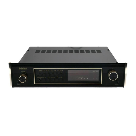
McIntosh MR80 User manual

ReadingTime:32Minutes
Price:$2.00
THEMclNTOSHMR80DIGITALFMTUNER

VARIOUSREGULATORYAGENCIESREQUIRETHATWEBRINGTHEFOLLOWING
INFORMATIONTOYOURATTENTION.PLEASEREADITCAREFULLY.
WARNING:TOPREVENTFIREORSHOCK
HAZARD,DONOTEXPOSETHISUNITTO
RAINORMOISTURE.
TheMclntoshyouhavepurchasedisa Model
MR80.Ithasa serialnumberlocatedontherear
panelofthechassis.Recordthatserialnumber
here:
SerialNumber
Themodel,serialnumberandpurchasedateare
importanttoyouforanyfutureservice.Recordthe
purchasedatehere:
Purchasedate
Uponapplication,MclntoshLaboratoryprovidesa
Three-YearServiceContract.YourMclntoshauthor-
izedserviceagencycanexpediterepairswhenyou
providetheServiceContractwiththeinstrumentfor
repair.Toassist,recordyourServiceContract
numberhere:
ServiceContractNumber

YourMR80DigitalFMTuner
cangiveyoumanyyearsof
satisfactoryperformance.Ifyou
haveanyquestions,pleasecontact:
CUSTOMERSERVICE
MclntoshLaboratoryInc.
2ChambersStreet
Binghamton,NewYork13903-9990
Phone:607-723-3512
TakeAdvantageof3 years
ofContractService...
FillintheApplicationNOW.
Contents
SERVICECONTRACTINFORMATION. ..1
INSTALLATION..2
HOWTOCONNECTAND
BACKPANELINFORMATION...4
FRONTPANELINFORMATION
ANDUSEOFCONTROLS.. .6
TOPPANELINFORMATION
ANDSECONDARYCONTROLS...8
PERFORMANCELIMITS. . .9
PERFORMANCECHARTS.-10
TECHNICALDESCRIPTION.14
BLOCKDIAGRAM..20
MclNTOSHTHREEYEARSERVICECONTRACT
AnapplicationforA THREEYEARSERVICECONTRACTisincludedwiththismanual.
Thetermsofthecontractare:
1.Mclntoshwillprovideallparts,materials
andlaborneededtoreturnthemeasured
performanceoftheinstrumenttothe
originalperformancelimits.TheSER-
VICECONTRACTdoesnotcoverany
shippingcoststoandfromtheauthoriz-
edserviceagencyorthefactory.
2.AnyMclntoshauthorizedserviceagency
willrepairMclntoshinstrumentsatnor-
malservicerates.Toreceiveservice
underthetermsoftheSERVICECON-
TRACT,theSERVICECONTRACTCER-
TIFICATEmustbepresentedwhenthe
instrumentistakentotheserviceagency.
3.Alwayshaveservicedonebya
Mclntoshauthorizedserviceagency.If
theinstrumentismodifiedordamaged
asa resultofunauthorizedrepair,the
SERVICECONTRACTwillbecancelled.
Damagebyimproperuseormishandl-
ingisnotcoveredbytheSERVICE
CONTRACT.
4.TheSERVICECONTRACTisissuedto
youastheoriginalpurchaser.Topro-
tectyoufrommisrepresentation,this
contractcannotbetransferredtoa se-
condowner.
5.ToreceivetheSERVICECONTRACT,
yourpurchasemustbemadefroma
Mclntoshfranchiseddealer.
6.Yourcompletelyfilledinapplicationfor
theSERVICECONTRACTmustbepost-
markedwithin30daysofthedateof
purchaseoftheinstrument.
7.ToreceivetheSERVICECONTRACT,all
informationontheapplicationmustbe
filledin.TheSERVICECONTRACTwill
beissuedwhenthecompletelyfilledin
applicationisreceivedbyMclntosh
LaboratoryIncorporatedinBinghamton,
NewYork.
8.UnitsinoperationoutsidetheUnited
StatesandCanadaarenotcoveredby
theMclntoshFactoryServiceContract,
irrespectiveoftheplaceofpurchase.
Norareunitsacquiredoutsidethe
U.S.A.andCanada,thepurchasersof
whichshouldconsultwiththeirdealer
toascertainwhat,ifany,servicecon-
tractorwarrantymaybeavailablelocally.
Copyright1980© byMclntoshLaboratoryInc.
1

HowtoConnectand
BackPanelInformation
Refertopage5.
AUDIOOUTPUTS
UsetheFIXEDOUTPUTjacksontherearpanelto
feedprogramtoa stereocontrolpreamplifieror
otherequipmentwhichhasitsownvolumecontrol.
ThefrontpanelVOLUMEcontroldoesnotaffectthe
loudnessofthetunerattheFIXEDOUTPUTjacks.
Theoutputlevelisa nominal1 voltfor100%FM
modulation.
UsetheVARIABLEOUTPUTjackstoconnectto
equipmentsuchasa poweramplifierora tape
recorderwherecontrolofthevolumeatthetuneris
desired.TheoutputattheVARIABLEOUTPUTjacks
isa nominal2.5voltsfor100%FMmodulation.
Thereisnodifferenceinthesignalqualityateither
pairofoutputjacks.
BothpairsofOUTPUTjacksmaybeusedsimul-
taneously.Theoutputimpedanceatbothoutputsis
verylowsothatlongaudiocablescanbeused
withouta lossofhighfrequenciesduetocable
capacity.
RFINPUTS—ANTENNACONNECTIONS
Twooffourdifferentantennasystemscanbe
usedwithyourMR80.1)anoutdoorFMantenna,2)
anallchannel(UHF-VHF-FM)antenna,3)a cablein-
putfromyourlocalcablecompany,or4)theindoor
dipolesuppliedwiththeMR80.A switchisprovided
onthetoplevelsetpaneltoselectbetweentwoof
thefoursystemsmentioned.
Anoutdoorantennaisrecommendedforoptimum
performanceinallareas.Infringeareas,bestresults
willbeobtainedwitha highlydirectionalFMan-
tennausedinconnectionwitha rotator.Rotatethe
antennauntilthebestreceptionisobtained.Con-
necta 300ohmoutdoorantennatothe300WAN-
TENNA(red)terminals.Connecta 75ohmantenna
and/or75ohmcablesystemtothecoaxialantenna
jack.
Aflexiblefoldeddipoleantennasuppliedwith
yourMR80maybeusedinurbanorinhighsignal
strengthareas.Theflexibilityofthethinflatwire
assemblypermitsittobeplacedundera rug.tacked
behindthestereoorplacedinanyotherconvenient
location.Insomecasesitmaybenecessarytoposi-
tiontheantennaforbestsignalreception.This
shouldbedonebeforeitispermanentlylocated.
Avoidlocatingthisantennanexttootherwiresor
metalobjects.Thisantennamaynotproveeffective
inhouseshavingmetalsidingormetalcladinsula-
tion.
Thecablesignalfroma localcablecompanyora
secondFMantennawith75ohmsimpedancemay
beconnectedtothecoaxialcablejack.
REMOTESCAN
TheREMOTESCANCONTROLSIGNALjackisto
beconnectedtothecablepushbuttonassembly
suppliedwiththeMR80forremotetuning.Plugthe
cableintotheCONTROLSIGNALjack.Pressingthe
pushbuttonattheendofthecablecausestheMR
80toscantothenextstation.Themodeofscancan
beselectedbytheSTATION'Sslideswitch.Inthe
PRESETpositioneverytimethepushbuttonis
depressedtheMR80willscantothenextpresetsta-
tion.IntheALLpositiondepressingthebuttonwill
causetheMR80toscantothenextstation.
IfREMOTEtuningisnotused,leavethejackfree
ofanyconnection.
SCOPE
Theverticalandhorizontalscopejacksarepro-
videdtoconnecttoa maximumperformancein-
dicatororanoscilloscopeforindicationofFM
multipathandsignalstrength.Connectthevertical
jacktotheverticalinputoftheindicatorandthe
horizontaljacktothehorizontalinput.
UNSWITCHEDACPOWEROUTLET
Thisoutletmaybeusedtopowerauxiliaryequip-
mentsuchasanantennarotatorora maximumper-
formanceindicator.Powerisavailablewheneverthe
MR80isconnectedtoa powersource.
4

FMCABLE
INPUTOR
2ND75WANTENNA
LEAD-IN
FMANTENNA
OPTIONAL
75W
ANTENNA
LEAD-IN
REMOTECONTROL
PUSHBUTTON
POWERAMPLIFIER
PREAMPLIFIER
LEFTSPEAKERRIGHTSPEAKER
5
MAXIMUMPERFORMANCE
INDICATOR
OR
OSCILLOSCOPE
TOAC
POWER
SOURCE

FrontPanelInformationand
UseofControls
TheMR80Tunerhasthemostflexiblecontrol
systemeverdesignedina stereoFMtuner.Correct
useofthesecontrolswillyielda higherlevelofper-
formancethanpreviouslypossiblewithconven-
tionaltuners.
VOLUMECONTROLANDACPOWERSWITCH
TheVOLUMEcontrolhasbeenprecisiontracked
throughoutthelisteningrange(0to- 65dB)forac-
curatestereobalance.
ItsetstheoutputleveloftheVARIABLEOUTPUT
jacksandthefrontpanelHEADPHONEjack.The
FIXEDOUTPUTjacksarenotaffectedbytheposi-
tionoftheVOLUMEcontrol.TheACpowerswitchis
partoftheVOLUMEcontrol.TurningtheVOLUME
controlfullycounterclockwiseturnstheACpower
off.
TUNINGCONTROLSANDFREQUENCYDISPLAY
FrequencyDisplay
TheFrequencyDisplayindicatesthereceivedfre-
quencytothenearest100kHz.
Tuning
TherearefourmethodsoftuningyourMR80.
Automaticselectionofthetuningmethodispro-
videdbytouchsensorsassociatedwitheachofthe
tuningcontrols.
ManualTuning
WhenpowerisappliedtotheMR80,thecircuitry
automaticallyselectsthemanualorknobtuning
controlmode.Turningthetuningknobclockwise
willincreasethereceivedfrequency.Counterclock-
wisedecreasesthereceivedfrequency.
Note:WhentheMR80isoperatedbutisnotcon-
nectedtoanyotherdevice(preamp,poweramp,
antenna,testequipment,etc.),thereisa chancethe
frequencydisplaywillblankoutwhentuningwith
themaintuningknob.Thisisnormalandcaneasily
becorrectedbyreversingthe120VAClineplugorby
connectingtheMR80toanyotherequipment.
AutoScan
AUTOSCANisprovidedbytwotouchpadsim-
mediatelytotheleftofthetuningknob.Thesetwo
touchpadsstartthetunersearchingfora newsta-
tion.Thesmallarrowwilllightnexttothepad
touchedandindicatethedirectionofscanning.It
willscaninthedirectionchosenuntilitstopsata
stationorreachestheendoftheband.Attheband
endthetunerwillreverseitsscandirection.
Preset1,2,3 & 4
Thesetouchpadslocatedtotheleftofthefre-
quencydisplayselectoneofthefourpresetsta-
tions.Justtouchtooperate.A smallrectanglewill
lightabovethepadindicatingwhichpresethasbeen
selected.
RemoteSCAN
RemoteSCANofeitherthepresetsorallstations
isprovidedforasdescribedunderbackpanelinfor-
mation.
INDICATORLIGHTS
Threeindicatorlightsareprovidedimmediatelyto
theleftofthepresettouchpads.Theuppermost
STEREOindicateswhena stereobroadcastisbeing
received.Thesecond,LOCK,indicateswhenthe
tunerislockedtothestation.Thelockcircuitinthe
MR80isuniqueinthattunedfrequencyislockedto
thestation,nottoaninternalstandardasinthecase
ofmanydigitaltuners.ThisallowstheMR80tobe
tunedtoanyfrequencywithintheFMbandandlock
onthatfrequency.Otherdigitaltunerscanonlylock
onspecificchannelassignments.Thislockcircuitis
sopowerfulthatitmustbedisabledinordertotune
thetuner.Youwillnoticethatthemomentthatyou
touchanyoneofthetuningcontrolsthelocklight
extinguishesandonlycomesonwhenthestationis
properlytuned.Oncelockhasbeenestablishedit
willremainonevenifthestationbeingreceived
shoulddriftupto2 megacycleseithersideofthe
centerofthecarrier.Thus,perfecttuningisalways
assured.Thethirdindicatorlight,FILTER,indicates
whenthestereonoisefilterisinoperation.Thein-
dicatorlightsareinthreedifferentcolors:redfor
STEREO,amberforLOCK,andgreenforFILTER.
SELECTIVITYSWITCH
TwodegreesofIFselectivityareselectablebythe
SELECTIVITYswitch.TheNARROWornormalposi-
tionprovidesadequateselectivityforstereorecep-
tionevenunderseverereceivingconditions.Five
linearphasepiezoelectricIFfiltersprovidelow
distortionreceptionwiththishighdegreeofselec-
tivity.SettingtheSELECTIVITYswitchtoSUPER
NARROWaddsanadditional4-pole4-zeroquartz
crystalfiltertothefivepreviouslymentionedfilters.
UsetheSUPERNARROWpositiontoreceivesta-
tionsfromdistantcitieswhichareonchannelsadja-
centtolocalstations.Theremaybeuseablesignals
whichwereneverheardbeforewithordinaryFM
tuners.
6
SIGNALCOLUMN
AcolumnofLEDlampsrespondtothesignal
strengthofthestationbeingreceived.Thestronger
thesignalthehigherthecolumnreaches.Thereisa
controlonthetunertoppaneltoadjustthecolumn
heightforfullscalewhenreceivingthestrongest
signalinyourlisteningarea.
FILTERSWITCHANDFUNCTIONINDICATOR
TheMR80FILTERswitchprovidesautomatic
stereonoisereductiononweakstereostations.With
theswitchintheAUTOpositionthefilterwillbeon
onlywhenthestationisbroadcastinga stereopilot
toneandthesignalstrengthisbelow100microvolts.
WiththeswitchintheINpositionthefilteriscon-
nectedatalltimes.Thefilterhasnoaffectonmono
stations.Thefilterfunctionindicatorlightglows
greenwhenthefilterison.
MODESWITCH
AtwopositionMODEswitchisprovidedsothat
youmayselecteitherautomaticstereoormono
reception.IntheSTEREOpositionthetuner
automaticallyswitchesfrommonotostereomode
whena pre-determinedsignaltonoiseratiohas
beenreached.IntheMONOpositionallstationswill
bereceivedmonophonicallybuttheSTEREOindicator
willlightifthestationisbroadcastinginstereo.
HEADPHONEJACK
AHEADPHONEjackisprovidedtodrivelowim-
pedancedynamicheadphonesfromaninternal
poweramplfier.
SCANCONTROL
TheSCANcontroladjuststhespeedatwhichthe
tunersearchesforthenextstation,whenusingthe
AUTOSCANmodeoftuning.Ifthedialiscrowded
withstationsusea slowscanspeed.Iftherearefew
stationsfastscanningcanbeused.
MUTINGCONTROL
MUTINGsuppressesthebackgroundnoiseand
hissnormallyheardbetweenstations.Turningthe
controlcounterclockwisetotheOUTpositiondis-
ablesthemutingcircuits.Turningthecontrolclock-
wiseincreasesthesignallevelrequiredtounmute.
ThiscontrolalsoadjuststhesensitivityoftheAUTO
SCANtuningcircuitsandthenumberofstations
youwillreceivewhenusingthistuningmode.
7

TopPanelInformationand
SecondaryControls
Onthetopofthechassisbehindthefrontpanela
recessedpanelcontainsthesecondarycontrols.
WhentheMR80isinstalledinthecabinetaccessto
thispanelmaybegainedbydepressingthetwo
PANLOCbuttonsandslippingtheunitpartiallyfor-
ward.
Preset1 thru4
ThePRESETtuningadjustmentsareusedtoset
thereceivedfrequencyforeachpreset.Toseta
presettothedesiredstation,touchthecorrespond-
ingpresetpadandatthesametimeadjustthe
presetcontrolonthetoppanelforthedesiredfre-
quencyindication.Youmusttouchthepadwhile
tuningtoholdthefrequencylockcircuitinactive,
otherwiseerroneoustuningwillresult.
Preselect
TheRFPRESELECTswitchswitchesanaddi-
tionaltunedcircuitbetweentheantennaandthe
firstRFstagetoimmunizeagainstoverload.Usethe
preselectorinverystrongsignalareas.
Input
TheINPUTswitchselectseitheranantennaor
cableastheRFinputsource.TheCABLEinputmay
alsobeusedasa secondantennainput.
Lock
Thisswitchwilldisablethelockcircuitsonly
whenthemaintuningknobisinuse.UsetheON
positionforallnormalreception.SwitchtotheOFF
positionwhenthereceivedstationhasa deepfade.
Thispreventsthefrequencylockcircuitfromchang-
ingtuningtolocktoanadjacentstrongerstation.
De-emphasis
The50/75msbuttonselectsthecorrectde-
emphasisforyourcountry.75msisusedontheNorth
Americancontinentand50msisusedinWestern
EuropeandtheFarEast.25msde-emphasisisalso
availablebydepressingthebuttonmarked
Note:Thenormaloperatingpositionofthefive
pushbuttonswitchesisfortheswitchestobeinthe
outorupposition.
SignalStrength
Usethiscontroltosetthesignalstrengthcolumn
tofullscaleforthestrongeststationinyourarea.
Thiscontrolisa sensitivityadjustmentforthesolid
statesignalstrengthindicator.Itmerelyadjuststhe
heightofthecolumn.Itdoesnotaffectthesensitiv-
ityofthetuner.
8

PerformanceLimits
PerformanceGuarantee
Performancelimitsarethemaximumdeviationfrom
perfectionpermittedfora Mclntoshinstrument.We
promiseyouthattheMR80,atthetimeofitspur-
chase,iscapableofperformanceatorexceeding
theselimitsoryougetyourmoneyback.Mclntoshis
theonlymanufacturerthatmakesthisguarantee.
Tuning:
88to108MHz
AntennaInputs:
One300Wbalancedandtwo75Wunbalanced.
IntermediateFrequency:
10.7MHz
Sensitivity:
9.3dBf(1.6mV)for35dBofquieting
14.7dBf(3mV)for50dBofquieting
13.2dBf(2.5mV)for3%totalnoiseandharmonicdis-
tortion
SignaltoNoiseRatio:
75dBbelow100%modulation
HarmonicDistortion:
0.2%20Hzto15kHz,monoorstereo
Typically,0.08%at1000Hz
IntermodulationDistortion:
0.15%monoorstereoforanycombinationoffre-
quenciesfrom20Hzto15,000Hzwithpeakmodula-
tionequalto100%orless.Typically0.1%
FrequencyResponse:
MonoandStereo± 1dB20Hzto15kHzwith75,50
or25mSdeemphasis
CaptureRatio:
1.5dB
Selectivity:
Adjacentchannel
Alternatechannel
SpuriousRejection:
110dB
Narrow
8dB
90dB
SuperNarrow
60dB
110dB
TunerIM(RF):
-23dBmfor2 signals1MHzapart
TunerInterceptPoint:
-10dBm75W
ImageRejection:
90dB
MaximumSignalInput:
8voltsacross75W(1W)antennaterminalwillnot
increaseharmonicorintermodulationdistortion.
AudioHum:
75dBdownfrom100%modulation
Muting:
70dBnoisereductionbetweenstations
MutingThreshold:
2mVto1000mV
SCARejection:
60dBminimum
StereoSeparation:
50dBto1000Hz
StereoFilter:
10dBnoisereduction
AudioOutput:
Variable:
2.5Vinto47k
Fixed:
1Vinto47k
GeneralInformation
PowerRequirements:
120volts50/60Hz.25watts
SemiconductorComplement:
57Transistors
68IntegratedCircuits
81Diodes
4LEDDisplays
18LED's
7NeonLamps
MechanicalInformation
SIZE:Frontpanelmeasures16incheswide(40.6cm)
by5 7/16incheshigh(13.8cm).Chassismeasures
143/4incheswide(37.5cm)by4 13/16incheshigh
(12.2cm)by13inchesdeep(33cm),includingcon-
nectors.Knobclearancerequiredis1 1/4inches(3.2
cm)infrontofmountingpanel.
FINISH:Frontpanelisanodizedgoldandblackwith
specialgold/tealnomenclatureillumination.
Chassisisblack.
MOUNTING:ExclusiveMclntoshdevelopedprofes-
sionalPANLOC
WEIGHT:27pounds(12.2kg)net,39pounds(17.7kg)
inshippingcarton
9

PerformanceCharts
SIGNALINPUT
10
SIGNALINPUT

11
FREQUENCYINHERTZ
FREQUENCYINHERTZ
FREQUENCYINHERTZ

12
FREQUENCYINHERTZ
FREQUENCYINHERTZ
FREQUENCYINHERTZ

13
FREQUENCYINHERTZ
FREQUENCYINHERTZ
FREQUENCYINHERTZ

TechnicalDescription
Engineeringdirectiondictateda tunerdesign
governedbyinsistenceongreatflexibilityandease
ofuse.ThishadtobedonewhiledesigninganRF
sectionwithgreatsensitivityandtheworld'sbest
selectivityinkeepingwiththeneedsoflowdistor-
tion.Thesevalueswereachievedandtheyretainthe
Mclntoshreputationofoutstandingperformance,
longlifeandreliability.
RF-IFSECTION
IntheANTSWITCHsixRFPINdiodesarecon-
nectedasa singlepoledoublethrowswitch.This
allowstheuseoftwoantennasortheuseofan
antennaanda cable.Inputtooutputisolationofthis
switchisgreaterthan75dB.
FollowingtheANTSWITCHisanRFtunerofex-
ceptionalperformance.Thisperformanceisachiev-
edbytheuseofa lownoisejunctionFETanda high
powerbipolartransistor(aheatsinkisused)con-
nectedasa cascodeamplifier.Thisconnection
allowshighgain,lownoise,andhighoutputlevels
withouttheneedforneutralization.Twoadditional
PINdiodesareusedtoinserta secondtunedanten-
naPreselectorcircuitduringstrongsignalrecep-
tion.Forlowerintermodulationdistortionthetuned
circuitsaretunedbya seriesparallelconnectionof
fourmatchedvaractordiodes.Thiscircuitandthe
hightuningvoltage(5-26volts)eliminatestheRFin-
termodulationdistortioncausedbydiodenon-
linearities.
AftertheRFamplifiertwoparalleltunedcircuits
areusedtoprovidetheproperloadimpedancefor
thebipolartransistor.Theuseoftwotunedcircuits
atthislocationgreatlyimprovestheimagerejection
andoverloadperformanceofthetuner,aswellasin-
creasingtheRFselectivity.
Thefollowingbalancedmixerisa matcheddual
J-FETandbipolartransistorcircuit.A lowloss
toroidalphasesplittingtransformerisusedasan
impedancematchingnetworkinthegatecircuitof
themixer.Attheoutputa balanceddoubletuned
transformerisusedasthedrainload.Thisarrange-
mentgivesgreatimmunitytomixeroverloadinthe
presenceofa verystrongsignal.A bipolartransistor
isusedasanoscillatorbuffertopreventoscillator
pullingonstrongsignals,andastheconstantcur-
rentsourceforthedualJ-FETmixer.
TheMR80hasthenarrowestIFbandwidthever
usedina stereotuner.Itisthecorrectwidthtolet
justoneFMstationthrough.Theexcellentselectivi-
tyoftheMR80(210kHzwideat60dBdown)permits
tuningtostationsthatareimpossibletoreceiveon
ordinarytuners.
Constantdelaydesigntechniquesareusedinthe
4-pole4-zerocrystalfilterusedintheSUPERNAR-
ROWposition.However,duetotheextremeselec-
tivity,delaydistortionisveryslightlyincreasedover
theNARROWselectivityposition.
Fourdifferentialamplifiers,coupledwithPHASE-
LINEARmonolithicfilters,comprisetheNARROW
selectivityandsignalstrengthsectionsoftheIF
amplifier.Onehalfofeachdifferentialamplifierout-
putdrivesa filterandthesecondoutputdrivesa full
waverectifiercircuit.Theoutputsofthesefour
rectifiercircuitsaresummedattheinvertinginputof
anoperationalamplifier.A fifthrectifiercircuitthat
isdrivenfromthelimiterisalsosummedattheinput
totheoperationalamplifier.Theoutputoftheopera-
tionalamplifierisa voltagethatisproportionalto
thelogoftheRFinputlevel.Dynamicrangeisfrom
2mVtoover2V,thatis,greaterthan120dB.A solid
statesignalstrengthmeterisusedasa frontpanel
indicationoftheincomingRFsignallevel.Twelve
LED'sareusedinplaceoftheconventionalmeter
movement.TheLED'shavean almostunlimitedlife.
ThefastresponseoftheLED'splainlyshows
multipathsignalsandantennamisorientation.To
betterusethewidedynamicrangeofthefivesignal
strengthdetectors,anadjustmentisprovidedto
reducethefullscalesignalfrom100,000mVtoany
valuebelowthat.Thismetercanbesettogivea full
scaleindicationona signalaslowas2mV.This
allowssettingthesignalmetertoindicatefullscale
onthestrongeststationintheusersarea.Thenthe
signalstrengthmeterindicatestheRFlevelofall
stationsreceivedrelativetothestrongestinthe
listener'sarea.
Thesignalstrengthvoltageisalsousedtocontrol
mono/stereoswitching,stereofilterinsertion,
muting,andautomaticscanstop.Becauseofit's
widerangeandhighrepeatabilitythiscontrol
voltageisalsousedtoadjustthestereoseparation
atlowRFsignallevels.Thisproducesthemaximum
signaltonoiseratiopossibleforallsignallevels.
FollowingtheselectivitysectionoftheIFampli-
fieristheLIMITER.A totalgainof80dBisusedin
thiscircuit.Theuseofveryhighgaininthelimiter
circuitproduceshardlimitingwithverygoodim-
pulsenoiserejection.Limiterbandwidthisgreater
than50MHz,producingexcellentdetectorcapture
characteristics.
AbroadbandFoster-Seeleydiscriminatorisused
asthedetector.Thisdetectorcoupledwiththe
broadbandlimiterproducesunmeasurablenoise
anddistortion.A highspeedbufferamplifierfollow-
ingthedetectorisolatesthedetectorfromallvaria-
14

tionsinloadimpedance.Thispreventschangesin
audiocablelengthsoutsidethetunerfromaffecting
thedetectorperformance.
FMSTEREOMULTIPLEX
Theheartofthemultiplexsectionisa newthird
generationphaselockedloop(PLL)stereodecoder
integratedcircuit(IC).ThisPLLICincorporatestwo
specialsystems,anautomaticvariableseparation
controlcircuittoreducebackgroundnoisewhen
receivingweakstereostations,andtri-leveldigital
waveformgenerationwhicheliminatesinterference
fromSCAsignalsandfromthesidebandsofadja-
centchannelFMsignals.
Thevariableseparationcontrolisoperatedfrom
theIFamplifier'ssignalstrengthdetector.A smooth
transitionisprovidedfrommonotostereoorfrom
stereotomonoatweaksignallevelstoprovidethe
optimumsignaltonoiseratioandbeststereo
separationfortheprevailingsignalconditions.The
circuitoperatesonlyduringstereoreception.Itswit-
chesautomaticallytomonophonicifthe19kHzpilot
toneisabsent.
InthePLLtheinternaloscillatoroperatesat
228kHz,lockedontothe19kHzpilottone.The
228kHzfeedsa 3 stageJohnsoncounterviaa binary
dividertogeneratea seriesofsquarewaves.
SuitablyconnectedNANDgatesandexclusiveOR
gatesproducethetri-leveldrivewaveformforthe
variousdemodulatorsinthecircuit.Theusual
squarewaveformshavebeenreplacedinthePLL
anddecodersectionsbytri-levelwaveforms.These
tri-levelformscontainnoharmonicswhichare
multiplesof2 or3.Thiseliminatesfrequency
translationanddetectionofinterferencefromthe
side-bandsofadjacentstationssincethethirdhar-
monicofthesub-carrier(114kHz)isexcluded.Italso
eliminatesinterferencefromSCAbroadcastssince
thethirdharmonicofthepilottone(57kHz)isexclud-
ed.Unwantedspuriousaudiblecomponentsand
phasejitterinthePLLareinherentlyeliminatedby
thistechnique.
Additionaladvantagesofthephaselockedloop
stereodemodulationaretheeliminationofinduc-
torstominimizedrift,integrallampdrivingcapabili-
tytoindicatethepresenceofthe19kHzpilotcarrier,
excellentchannelseparationovertheentireaudio
frequencyrange,extremelylowdistortion,lowout-
putimpedance,andtransient-freemono/stereo
switching.
AUDIOCIRCUITS
FollowingtheMPXdecoderisthethreeposition
deemphasisswitch.Thethreedifferentpositions
allowtheMR80tobeusedinNorthAmericawith
standard75msdeemphasisandinWesternEurope
andtheFarEastwith50msdeemphasis.The25ms
positionisforusewithanexternalnoisereduction
adapter.
Anelectronicallyswitchedfiltercircuit,im-
plementedwithtwoJ-FETsofa quadJ-FET
package,isusedtoreduceoutofphasenoisewhen
inthestereomodeandtunedtoa weakstation.This
filterisactuallya twin-Tbandpassthatblendsthe
highandlowfrequencies,leavingseparationunaf-
fectedatmid-frequencies.Thisresultsina greatly
improvedstereoimagewhenthefilterisrequired.
Acombinationofthreeinputsareusedtocontrol
theswitchpointofthefilter.Thefirstisthefront
panelswitch.Thefilterisonlyactivewhenthis
switchisintheAUTOorONposition.IntheONposi-
tionthefilterisinthecircuitforallstationsmonoor
stereo.IntheAUTOpositionthefilterwillswitchin
whenthestationistransmittinga stereopilotsignal
andthesignalstrengthisbelow100mV.
InthesamequadJ-FETpackagearethetwoFETs
thatareusedforthemutingcircuit.TheseFETsare
controlledbythelogicalANDingofthreesignals.
Thefirstsignalisthedeviationorcentertune,this
detectswhenthetuneriscorrectlytunedtothe
centeroftheFMchannel.Thesecondsignalisthe
signaltonoiseratio.Onlywhenthereissufficient
signalwillthetunerbeallowedtounmute.Signalto
noiseratioismeasuredbya specialbandpass
amplifiercenteredaround138kHz.Thisfrequencyis
usedtopreventfalsetriggeringduetoadjacent
channelandovermodulationproducts.Thethird
signalistheRFsignallevelthatisderivedfromthe
fivesignaldetectorcircuits.A frontpanelcontrol
(MUTINGLEVEL)adjuststhereferenceleveltoa
voltagecomparator.Theotherinputtothecom-
paratoristhesignalstrengthvoltage.WhentheRF
levelexceedsthepresetreferencelevel,a signalis
senttothemutinglogictobeANDedwiththeother
twosignals.Thisadjustmentallowstheunmute
leveltobesettoanyvaluefrom2mVtogreaterthan
1000mV.
Thiswiderangeisnecessaryforthetunertoscan
properlyinallsignalconditionsandprovidethebest
combinationofeaseofusewithmaximumintersta-
tionnoisesuppression.
19AND38kHzFILTER
AnLCtunednotchfilterisusedtoeliminateany
beatnoteinterferencewiththebiasoscillatorina
userstaperecorder.Thisfilterisdrivenfroma filter
bufferamplifierandterminatedbytheoutputopera-
tionalamplifier.Theseamplifiersprovidethe
necessaryinputandoutputimpedancesforproper
phaseresponse.Theoutputamplifierisalsousedas
anaudiobandpassfiltertopreventunwantednoise
andtransientsfrombeingpassedontothehead-
phoneamplifier.
HEADPHONEAMPLIFIER
Theheadphoneamplifieriscapableofdrivinga
pairofdynamicheadphoneswithlessthan.02%
15

harmonicdistortion.Becauseofitsextremelylow
THDandpowercapability,itisalsothemainoutput
amplifier.
TOUCHSENSOR
Thetouchsensorconsistsofthreefunctional
elements:1)Inputbuffersandstaticprotectioncir-
cuits.2)Latches,and3)Encoder.Thesevensensors:
KNOB,PRESET1 to4,UPandDOWNSCANarein-
putstotheseveninputbufferamplifiers.Theseper-
forma dualfunction.Firsttheinputsarebiasedtoa
highlevelbya veryhighresistance.Secondthebuf-
fersaredesignedtodetecta negativetransition
froma referencelevel.Whena sensoristouched,
thestraycapacityofthehumanbodyshuntssome
ofthisreferencesignaltoground.Thisreference
signalisderivedfromthe228kHzoscillatoronthe
multiplexcircuitboard.Thismeansaltnoisecom-
ponentsofthereferencesignalarea multipleof
19kHz,andwillbefilteredoutbythe19and38kHz
filters.Thesecondphaseofthisreferencesignalis
usedtotransfertheoutputofthebufferamplifiers
intothelatches.Thelatchesareusedastemporary
storagetopreventfalsetriggeringduetostaticand
voltagetransients.
Theoutputfromthelatchedinputsaresuppliedto
theencoder,whichperformstwofunctions.First,it
putsinordertheinputs,assigninghighestpriorityto
thetuningknobandthelowesttothedownscan
sensor.Second,itencodestheinputwiththe
highestpriorityintoa binarycodeddecimalword
andoutputsthistothedecodercircuit.Thisdecoder
reconvertstheBCDwordbackintoa 1 ofsevenline
code,indicatingthesensorthatistouched.Anaddi-
tionalinputtothedecoderisthereferencephasein-
putthatinhibitsthedecoderduringclockedgetran-
sitions.Thisisdonetopreventfalsetriggeringdue
tonoiseglitchesandpartialcontactwiththetouch
sensor.
PRESETSCAN
Thesevenoutputsfromthetouchcontroland
decodergotothepresetscancircuits.Inthepreset
scanisanelectronicswitchanda counter.A switch
ontherearpanelselectswhetherthetunerscansall
stationsoronlythepresetstations.Thecircuit
operatesinthepresetscanmodeasfollows:Whena
pulseisreceivedattherearpanelconnectorthe
counterisindexedbyone,thenthesevenpoledou-
blethrowswitchconnectstheinputtothetuning
controllogictotheoutputofthecounter.Thecon-
trollogicthenselectsthepresetthatisrepresented
bythecounteroutput.Attheendofthepulsethe
counterisdisconnectedandthelockcircuitauto-
maticallyfinetunesthetunertothecenterofthe
channel.
Wheninthescanallstationsmode,theinput
pulseisroutedtothescancircuitryonthetuning
controllogicboard.Thelogiccircuitrywillthen
selecttheautoscancircuitandstartsearchingfor
thenextacceptablestation.Thedirectionofscan
willbethelastselectedscandirectionandwill
changewhenthebandlimitisreached.
Theremoteinputtothetunerisa groundasserted
logiclevelthatisnormallyat+ 15volts.Whenthis
lineisgroundedthetunerwillstartscanning.The
useofthislogicpermitsanynumberofremote
cablestobeconnectedtotheMR80.
CONTROLLOGIC
Thecontrollogicportionofthetunerismadeup
ofverylowpowercomplementaryMOSintegrated
circuits.Byusingthislogicfamilya verysignificant
powerreductionwasrealizedinthedesign.Withthe
lowerpowerconsumption,a veryrealreductionin
theoperatingtemperatureandanimprovementin
theoperatinglifeisachieved.
Averyimportantconsiderationinthedesignofa
digitaltuneristheamountofradiatednoisefromthe
digitalintegratedcircuits.Toachievelownoisethe
controllogicwasmadetooperateina staticmode
toentirelyeliminateanyinterference.Thisallows
thecontrollogicboardtobebuiltwithoutthe
shieldingnecessarytoreduceinterference.
Theseventouchsensorinputsfromthepreset
scanboardarestoredineightC-MOSflip-flop's.The
stateoftheflip-flop'sindicatewhichinputwasac-
tivelast.Onebitisusedforthemaintuningknob,4
bitsareusedtorepresentthe4 presets.Thescancir-
cuitryuses3 bitstotellifthescanisonoroff,setto
scanupordown,andthethirdissettoa zerowhen
thetunerreachesanacceptablestation.Thiscom-
plexgroupofcircuitsprovidesa levelofsophistica-
tionandeaseofoperationnotpossiblebeforeina
tuner.
Severaltimingcircuitsareusedtoprovidethe
varioustimesequencesanddelaysfortheproper
noisefreeoperationofthepresetandscancircuits.
Thefirstofthesemonostablecircuitsisusedasa
poweronclearthatresetsthecircuitstothemain
tuningknobmode.Duringthefourseconddelaythe
lockcircuitisinhibitedandthehighspeedmuting
inputtothemultiplexisheldhightomutethetuner
andpreventanynoiseortransientfromaffectingthe
restoftheuserssystem.Atthecompletionofthis
fourseconddelaythelockcircuitisenabled,locking
thetunertotheincomingfrequencyandunmuting
thetuner.
Whenoneofthefourpresetsisactivated,the
displayandaudioareinhibitedfortwosecondsfrom
whenthesensoristouched.Thelockcircuitis
disabledduringthetimethesensoristouched,to
allowthepresetstobesettotheproperfrequency.
Whenthesensorisreleasedthelockcircuitthen
tunestothecenteroftheFMstation.Duringnormal
operation(notsettingofthepresets)thetouchsen-
16

sorreactsina smallfractionofa secondsothe
tunerappearstochangestationsinstantaneously,
withoutanyinterstationnoiseevenwiththemuting
turnedoff.
Wheneitherofthescansensorsistouchedthe
tunerismutedandthedisplayblankedfortwo
seconds,thisallowsthetunertoreachthenextsta-
tionundernormallisteningconditionswithoutany
interstationnoise.Ifthescanspeedissettoa slow
settingandthemutingisturnedoff,interstation
noiseandveryweakstationswillbeheardafterthe
twoseconddelay,whichisveryusefulwhenremote
tuningisused.
DrivenfromthetuningcontrollogicaresixLED
lamps.Fourareusedtoindicatewhichofthe
presetsareinuse.Theothertwolampsindicatethe
directionofscan.Thesesixlampsandthefrequency
displayindicateata glancehowthetuneris
operatingandwhatpresetorscandirectionhas
beenchosen.
LOCKCIRCUIT
Aninnovativenewcircuitwasdevelopedforusein
theMR80.Thisnewcircuitallowscorrecttuning
withouttheuseofa centertunemeter.TheMR80
willbecorrectlytunedevenifthestationorthe
cablecompanyisnotonitscorrectfrequency.This
isdonebytheuseoftwooperationalamplifiers,
Adeviationsignalfromthedetectorisfedintothe
firstamplifier.Thiscircuitisa logamplifierthatpro-
ducesanoutputvoltageproportionaltothelogof
theDCcomponentinthedetectoroutput.Because
theoutput voltagecontainsaudiosignals, a second
amplifier,connectedasa switchedgainlowpass
filter,removestheaudiosignals.Thisamplifierhas
averyhighgainwhenthelockcircuitisonandunity
gainwhenthelockcircuitisoff.AnN-channelJ-FET
isusedasthegainswitchingelementinthe
negativefeedbackpath.Thefilteroutput,nowcalled
thecorrectionvoltage,isfedintoa scalingcircuit
thatcompensatesforthetuningdiodesnonlinear
frequencytovoltageresponse.Bothofthe
amplifiersoperatewithgreaterthan50dBofgainat
DC.Witha closedloopgainofgreaterthan100dB
thetuningerrorwhenlockedislessthan1kHzat
100MHz,or1 partin100,000.Thiserroristhesame
asa crystalcontrolledsynthesizerwiththeaddi-
tionalbenefitofbeingcorrectlytunedevenifthe
stationorthecablesignalisnotontheproper
frequency.
Becausethelockcircuitwilltracka stationevenif
itdrifts1MHz,thelockcircuitmustbeturnedofffor
theoperatortobeabletotunetheMR80.Thisisthe
reasonforthetouchsensoronthemaintuning
knob.Topreventthetunerfromlockingontoa
strongsignalnexttoa weaksignal,a circuitisused
tosensethestrongadjacentchannelsignalandin-
hibitthelockcircuitundertheseconditions.Onthe
topcovercontrolpanelisa manuallockON/OFF
switchthatinhibitsthelockcircuitonlyifthetuner
isinthemaintuningknobmode.Thisprovisionis
madefortestingthetunerandforcaseswherethe
stationbeingreceivedhasa deepfadetothepoint
oflosinglock.Iftheswitchissettotheoffposition
thelockcircuitwillworknormallyforallthepresets
andthescancircuit,butnotforthetuningknob.
SCANCIRCUIT
WiththevoltagetunedRFsection,automatic
scanningisimplementedwithoutanymovingparts
suchasmotors,flywheels,orstrings.Bytheelimina-
tionofallmovingparts,a muchgreaterdegreeof
reliabilityisachievedandtuningconvenienceim-
proves.
TheMR80scancircuitconsistsoffivesections:
1)switchingcircuit;2)bipolarcurrentsource;3)in-
tegrator;4)bandlimitdetector;and5}theauto-track
circuit.Thescanswitchingcircuitcontrolsthescan
functionbyswitchingtwoflip-flops,thescanon/off
flip-flopandthescanrun/stopflip-flop.Wheneither
ofthescanbuttonsortheremotecontrolstartsa
scancycle,thepresetbuttonsandtuningknobcir-
cuitsareswitchedoff,thelockcircuitisinhibited,
thedisplayisblanked,theaudioismuted,andthe
scanon/offflip-flopturnson.Thedisplayisblanked
andtheaudioismutedfortwoseconds.Thescan
on/offflip-flopswitchestheRFtuningcontroltothe
scanrampvoltage.
Dependingonthescansensortouched,the
bipolarcurrentsourceissettothepropervalue
(negativeforscanup,positiveforscandown).This
currentisadjustedbythefrontpanelSCANSPEED
controlforthepropersearchspeed.Therun/stop
flip-flopstopsorstartsthescansequence.Thisflip-
flopissetwhenevera scanstopsignalissentfrom
themultiplex.Toresettheflip-floponeofthescan
sensorsmustbetouched.
Intheintegratorportionofthescancircuitthecur-
rentisconvertedintoa timedependentrampvoltage
untila stopsignalisreceivedfromthemultiplex.
Whenthetunerhasstoppedona stationthetuning
voltageisstoredona speciallowleakagecapacitor.
Topreventdriftduetoleakagecurrents,guard
trackswereemployedaroundthenegativeinputto
theintegratoroperationalamplifier.Thisamplifieris
aspecialtypewithMOS-FETinputtransistorsthat
haveaninputresistanceofgreaterthan100million
megohms.Withspecialcircuitcomponentsand
printedcircuitlayout,driftinthescancircuithas
beeneliminated.Thepositiveinputtotheopera-
tionalamplifierisusedastheinputforthelockcor-
rectionvoltage.Thecorrectionvoltageisonlyap-
pliedafterthetunerhasstoppedscanningandfine
tunesthetunertothecenterofthestation.
Twocomparatorsconnectedtothetuningvoltage
inputintheRFsectionareusedforbandlimitdetec-
17

tion.Thecomparatorssensewhenthetuning
voltageexceedsthevalueneededfor87.5or
108.1MHzandgeneratesa pulsethattogglesthe
flip-flopcontrollingthebipolarcurrentsource,
changingthedirectionofscan.Ifa personattempts
toscanpastthebandends,bothscanindicatorswill
lightandthetunerwillhangatthebandlimituntil
thesensorisreleased.
Whenanyofthepresetsorthetuningknobareac-
tivetheautotrackcircuitisusedtoforcetheoutput
oftheintegratortoa valueequaltothecurrenttun-
ingvoltage.Duringtheturnondelaytheautotrack
ensuresthattheintegrator'soutputvoltageiswithin
thebandlimits.Thiscircuitallowsthetunertostart
searchingforthenextstationfromthecurrentloca-
tion.
FREQUENCYCOUNTER
Thecounteranddisplayformthedigital
equivalenttotheslideruledialandpointer,butwith
greateraccuracyandreadability.IntheRFsectiona
smallportionoftheoscillatorsignaliscoupledinto
thebufferamplifieronthecountercircuitboard.
Thisbufferamplifierismadewithemittercoupled
logiccircuitsandisusedtochangethesmall
oscillatorsignalintoa levelacceptablebythehigh
speedECLdivide-by-fourcircuit.Theoutputofthe
dividerislevelshiftedtolowpowerSchottkylevels
foruseintherestofthecountercircuit.Thedivided
localoscillatorsignalissampledfor40.96mSbya
synchronousgate,madefroma J-Kflip-flopto
eliminatethe± 1 counterror.Theactualcountingis
donebylowpowerSchottkyintegrateddecade
counters.IFfrequencyoffsetisaccomplishedby
presettingthecounterstothecomplementoftheIF
frequency,893.ThisallowssubtractingtheIFoffset
byaddingthenegativeoftheIFfrequency.
Thegatesignalisderivedfroma stable200kHz
crystaloscillatoranda binarydividermadefromLS
integratedcircuits.Twoothersignalsarederived
fromthedividerchain.Thefirstisusedtotransfer
theinformationinthedecadecounterstothe
displaybuffer.Thesecondisusedtoresetthe
countertothecomplementoftheIFfrequency.
Inthedisplayportion,threeTTLintegratedcir-
cuitsareusedasa latchtostorethefrequencyinfor-
mationandasconstantcurrentsourcestodrivethe
LEDfrequencydisplays.Byusingthelatches,a
flickerfreedisplayisassuredevenwhenthedisplay
ischanging.Theconstantcurrentsourcesimprove
reliabilitybyreducingthenumberofcomponents.
LEDdisplayswereusedbecauseoftheirvisibility,
characterfont,andverylonglife.
POWERSUPPLY
Specialdesignattentionhasbeengiventothe
powersupplysection.Nineseparatepowercircuits
areused.Sixoftheseareregulatedtopreventloss
ofperformanceduringa brownout.The- 15,- 5.2.
5,15and30vuseintegratedcircuit3 terminal
regulators,whilethe3macurrentsourceismade
withdiscretetransistorsbecauseofthehighvoltage
ontheinputterminal.Theremainingvoltagesareus-
edfortheheadphoneamplifierandthetouchcontrol
referencesignaldriver.
LAMPDRIVERS
Mclntosh,recognizingtheneedforimprovedrelia-
bility,hasdesigneda newcircuittodriveincande-
centlamps.Thisnewcircuitpreventsthefilaments
fromfailingduetonotchingwhenoperatedondirect
current.Thisfailuremodecanreducelamplifefrom
onehalftoonetenthofthedatasheetvalue.Inthe
MR80thethreelampsthatareusedforSTEREO,
LOCKandFILTERindicatorsareoperatedonACat
lowerthanratedvoltagetoextendtheusefullifeto
wellinexcessof15years.OnlyMclntoshbringsyou
thisfeature.
18

19

BlockDiagram
20
MclNTOSHMR80
Table of contents
Other McIntosh Tuner manuals

McIntosh
McIntosh MR 73 User manual

McIntosh
McIntosh MR65B User manual

McIntosh
McIntosh MR 7083 User manual

McIntosh
McIntosh MR66 User manual

McIntosh
McIntosh MR 77 User manual

McIntosh
McIntosh MR-55A User manual

McIntosh
McIntosh MR85 User manual

McIntosh
McIntosh M85 User manual

McIntosh
McIntosh MR85 User manual

McIntosh
McIntosh MR 71 User manual

McIntosh
McIntosh MR 71 FM User manual

McIntosh
McIntosh MR 78 User manual

McIntosh
McIntosh MR65B User manual

McIntosh
McIntosh MR 74 User manual

McIntosh
McIntosh MR-55A User manual

McIntosh
McIntosh MR85 User manual

McIntosh
McIntosh MX 114 User manual

McIntosh
McIntosh MR 500 User manual

McIntosh
McIntosh MR65 User manual

McIntosh
McIntosh MA6600 User manual