McLelland UWA-S5 TX User manual

www.mclellandmusic.com
UWA-S5 RX
UWA-S5 TX
POWER
ON
OFF
POWER
ON
OFF
UWA-S5
OWNERS MANUAL
5.8G Wireless Audio
Transmitter/Receiver (with Amplifier)

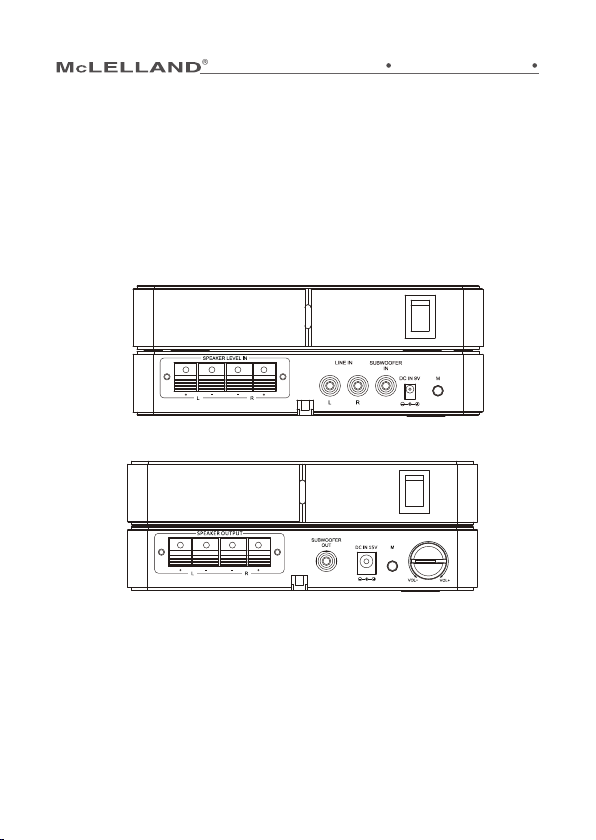
1. Make sure your amplifier is off. Connect the transmitter to your
amplifier's speaker output terminals with the provided 6-foot speaker
wire,matching polarities. Or connect your transmitter to the
amplifier's RCA output ports with RCA cables (not included).
2. Connect the supplied AC adapter (9V, 1.3A)to the DC IN 9V jack, then
plug it into a standard household outlet.
1. Connect the rear speakers to the receiver with speaker wires,
matching polarities.
2. Connect the supplied AC adapter (15V, 4A) to the DC IN 15V jack,
and then plug it into a standard household outlet.
■Make sure the exposed tips of the speaker wires do not
touch each other, and make sure they are fully inserted
into the terminals.
■This speaker kit is designed for connecting to your
amplifier surround speaker terminals only.
■For speaker wires that have proprietary connectors, you
may need to strip the end of the wires to allow
connection to the receiver. However, check with the
speake manufacturer before doing this, as it may void
the warranty.
■When the RCA cables are connected, audio input from the
speaker terminal will be mixed.
■Unplug the AC adapters from the AC outlet before
unplugging it from the transmitter or receiver.
■Use the supplied AC adapters only. Using an AC adapter
not designed for this product may cause damage.
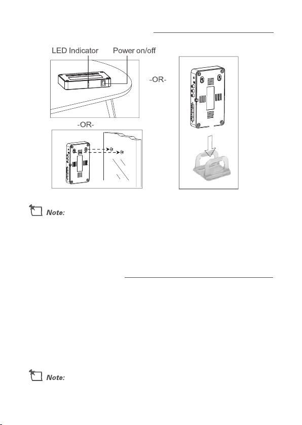
INSTALL THE TRANSMITTER
INSTALL THE RECEIVER

The transmitter and receiver must be placed within 100 feet for proper
operation. They can be placed horizontally on a flat surface, vertically
in the provided stands, or mounted on a wall using the mounting holes
on the bottom.
■ Transmitter ■ 9V AC Adapter ■ 15V AC Adapter ■ Receiver
■ Stands (2) ■ User's Guide ■ 6-foot speaker wire (2)
■ 5.8GHz digital wireless link provides crystal-clear audio signals.
■ Auto channel selection.
■ Up to 100 feet (30.5m) operation distance between transmitter and
receiver (line of sight).
PLACE THE TRANSMITTER AND RECEIVER
PACKAGE CONTENTS
FEATURES

1. Once the AC adapters are connected, the receiver LEDs light green.
The speaker kit enters standby mode.
2. Tum on your amplifier and then play the audio or video source
through your amplifier.
3. When an audio signal is detected by the transmitter and the
transmitter signal is detected by the receiver, the speaker kit will
automatically go into active mode. The transmitter and receiver LEDs
will both turn blue.
If you need to mount the receiver on a wall, install it
against the wall in such a way that the ventilation slots are
not blocked.
To optimize the reception performance, place the
transmitter and receiver in the same orientation.
After powering on, if there is no signal input within 17 minutes,
the speaker kit enters standby mode.
LED INDICATOR POWER ON/OFF
USE YOUR SPEAKER KIT

If you experience any
interference, press and hold
the M button on both units.
The units will then
automatically pair.
1. Power on the transmitter and receiver, and then turn on the amplifier
and adjust it to your normal listening level.
2. Adjust the receiver's VOL +/control to balance the front and rear
speaker sound level. This step is only necessary during first-time
installation of the speaker kit with your system.
3. After balance setup, simply use the volume control on your amplifier
to adjust speaker volume during playback.
CHANGE THE CHANNEL
ADJUST THE VOLUME BALANCE

Many surround-sound systems let you adjust the delay
between the front and rear speakers. To optimize your setup,
adjust the rear speaker delay response by about 20
milliseconds
Specifications are subject to change and improvement without
notice. Actual product may vary from the images found in this
document.
Audio Output Level: Subwoofer out: 470mv
Speaker out: 25W (Load at 4Ω)
Input Sensitivity: Line in: 470mV
Subwoofer in: 470mV
Speakerin: 7 V
Frequency Response: Subwoofer: 20Hz-200Hz
Speaker: 20Hz-20kHz
Audio Distortion: Subwoofer: <1 %
Speaker in: <10%
Signal to Noise Ratio: >80dB
Operation Distance: 100 ft (30.5m)
Dimensions (HxWxD): 6.9 X 3.9 X 1.6 inch (175x100x32mm)
Weight : 3.3 lb. (1.5kg)
OPTIMIZE YOUR SURROUND SOUND
SPECIFICATIONS

This equipment has been tested and found to comply with the limits for a
Class B digital device, pursuant to Part 15 of the FCC Rules. These limits
are designed to provide reasonable protection against harmful
interference in a residential installation. This equipment generates, used
in accordance with the instructions, may cause harmful interference to
radio communications. However, there is no guarantee that interference
will not occur in a particular installation. If this equipment does cause
harmful interference to radio or television reception, which can be
determined by turning the equipment o and on, the user is encouraged
to try to correct the interference by one or more of the following
measures:
■Reorient or relocate the receiving antenna.
■Increase the separation between the equipment and receiver.
■Connect the equipment into an outlet on a circuit dierent from that to
which the receiver is connected.
■Consult the dealer or an experienced radio/TV technician for help.
If you can not eliminate the interference, the FCC requires that you stop
using your products. Changes or modify cautions not expressly by the
party responsible for compliance could avoid the user’s authority to
operate the equipment.
This device complies with Part 15 of the FCC Rules. Operation is subject to
the following two conditions: (1) This device may not cause harmful
interference, and (2) this device must accept any interference received,
including interference that may cause undesired operation.
FCC INFORMATION
RoHS
COMPLIANT
This manual suits for next models
1
Table of contents