MCM Electronics WPIR3 User manual

1
BATTERYHOLDER
ANTENNA
GREEN RED
LIGHT LIGHT
PYRO
SENSOR
PULSE COUNT JUMPER TAMPER SWITCH
WPIR Motion Sensor
WPIR3
Introduction
The WPIR3 Motion Sensor is an infrared movement sensor, which is
battery operated and communicates with a receiver via radio
transmission (RF). This detector is easy to install, provides excellent
detection sensitivity and has a long battery life. The WPIR3 Motion
Sensor can transmit different codes to your Receiver:
1. Alarm
2. Tamper
3. Low Battery
•NEVER TOUCH THE PYRO SENSOR
•DURING THE WARM UP PERIOD, (first 5 minutes after installing the batteries) THE DETECTOR WILL NOT
RESPOND TO THE TAMPER SWITCH OR TO MOVEMENT IN FRONT OF THE DETECTOR. YOU MUST
WAIT 5 MINUTES BEFORE IT WILL RESPOND.
Setup
Remove the front cover of the detector by unclipping the case from the top. Once the case is open, you will see
a small square piece of insulation under one of the battery terminals. Remove this insulation. The Red & Green
LED's will flash together 6 times to confirm that the detector now has power connected. Now replace the front
cover.
Warm Up Period:
You must wait approximately 5 minutes for the
detector to warm up after connecting the
batteries. During this period the detector will
not detect or transmit. Once the detector has
warmed up, the green and red lights will flash
together 6 times to confirm that the warm up
period has finished. The detector will now
automatically enter Normal (Intelligent Power
Saving) Mode - refer to page 2.
Battery Type: 2 x Lithium button cells
Model: CR2450
Voltage: 3 Volts
+ +
IMPORTANT NOTES:
Made in Australia
A.C.N 001 621 610

2
Operation
Test Mode:
•This mode is used when installing detectors to check & adjust operation, and also when programming
detectors into your receiver. Refer to Receiver manual for programming instructions.
•Power the PIR up as previously described
•To place the detector in test mode, remove the front cover off the detector so that the tamper switch opens.
This tells the detector to enter test mode. Both the red and green lights on the detector will flash together 6
times. Now replace the front cover.
•The detector will stay in test mode for approximately 3 minutes. During this time, each movement into and out
of a infrared beam zone will be indicated via the LED’s.
•Each pulse detection will be indicated by a single flash of the GREEN light.
•Valid alarm detection will be indicated by the RED light flashing once (see pulse count).
•Both detector lights will flash together 6 times to indicate that test mode has finished.
•Once test mode has finished the detector will automatically enter normal mode.
Normal Mode: (Intelligent Power saving mode)
•The detector will enter this mode immediately after the warm up period. Normal operation is a very efficient
mode for preserving battery life.
•The GREEN light is NOT operational in this mode.
•After a valid detection, the detector will transmit the alarm code to the receiver (the red LED will flash once)
and then not respond for approximately 3 minutes. It will enter instead "intelligent power saving mode".
•After the three-minute period following a valid detection, the detector will be ready to detect again & transmit
the alarm signal.
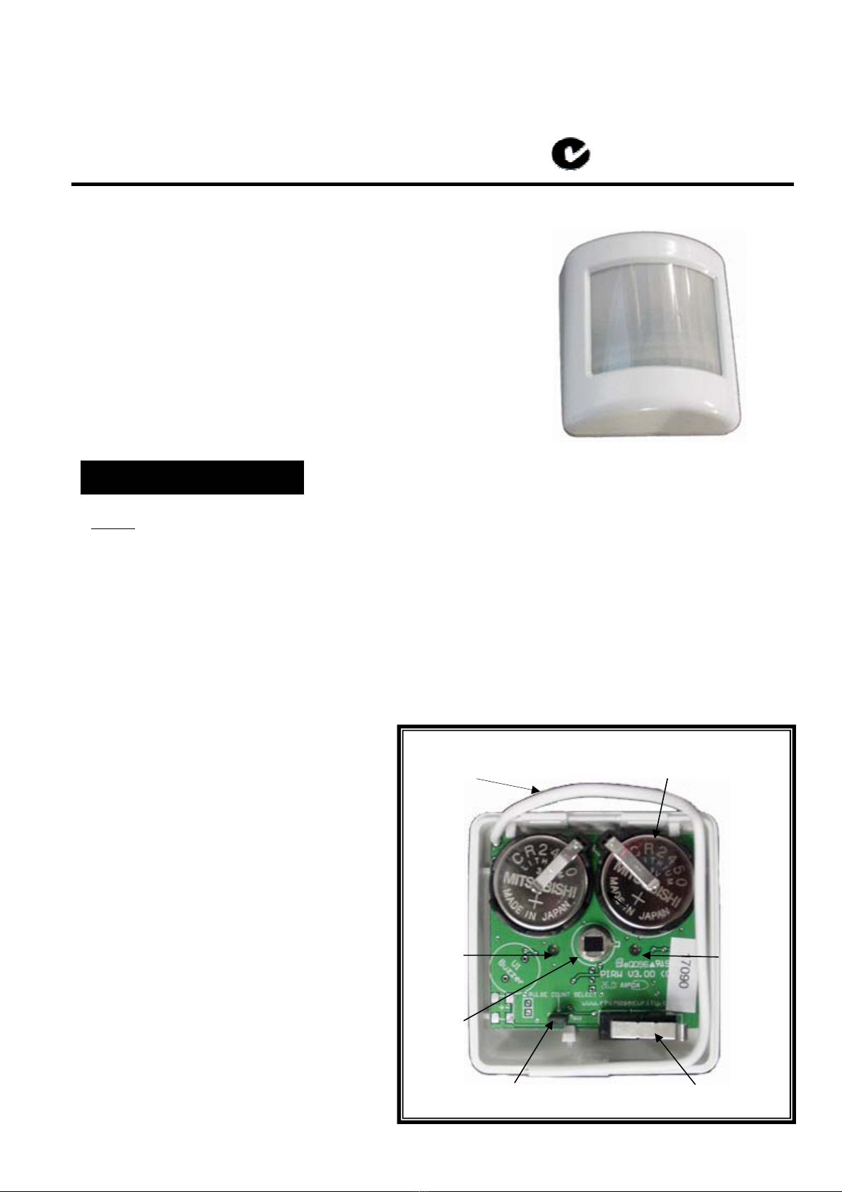
Pulse Count on Valid Detection:
•The pulse count feature enables you to adjust the real life detection sensitivity of the detector i.e. how much
movement is required to cause alarm detection. The pulse count can either be set to 2 or 3 via the jumper on
the PCB. If the jumper is placed across both pins of the jumper, then the detector will operate on 3 pulse
counts within 10 seconds to confirm a valid detection. If the jumper is removed or only placed on one pin,
then the detector will operate on 2 pulse counts within 10 seconds for a valid detection.
•On valid detection, the RED light will give a single flash, and will transmit the alarm detection code to the
receiver.
•Note: If you change this setting, it will take 3 minutes to take effect after you close the case. Alternatively,
press & then release the tamper switch before replacing the case for the setting to take effect immediately.
Tamper:
The tamper switch will open whenever the front cover of the detector is removed. A tamper signal is
automatically sent to the receiver. Each time this occurs the detector will also automatically enter
test mode.
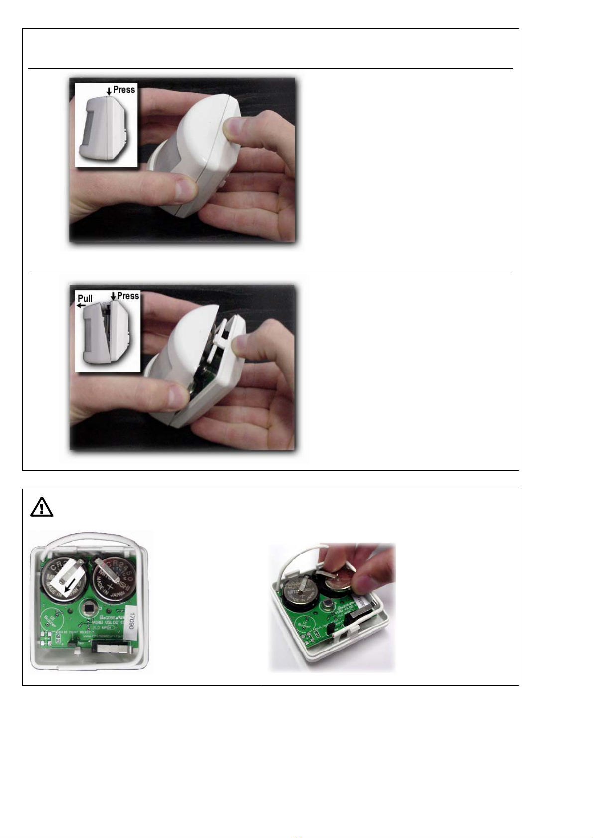
Low Battery Warning:
If the detector has flat batteries (combined power supply below 4.8 Volts) then on detection the RED
light will flash 6 times in a row instead of once. The batteries should be replaced immediately.
There are 3 different circumstances when the RED light will flash 6 times in a row instead of once:
i) When the tamper switch is opened to enter test mode after both red & green lights have flashed 6
times to indicate that the detector has entered test mode, the RED light only will flash 6 times in a row
to signal a low battery. It will send the low battery signal code to the receiver.
ii) Whenever detection is made in normal mode and the detector has flat batteries, the RED light will
flash 6 times in a row on a valid detection.
iii) If the detector has not had a valid detection within 8 to 12 hours and the detector has flat
batteries it will automatically send a low battery signal to the receiver.

3
Installation
•This sensor utilises the very latest in detection processing technology to
reduce the possibility of false alarms. However, correct mounting of the
detector is critical to ensure best detection or "catch" performance. You
can not just screw the sensor directly to a wall up high in a corner and
expect best performance. Please refer to the diagram & notes opposite.
Thoroughly walk test each sensor, and if detection is not acceptable in the
location you have chosen, adjust the angle of the sensor slightly & re-test.
You will find that a slight up/down angle change may improve catch
performance significantly.
•Mount the detector on your wall using the swivel mount provided at a
minimum height of 1.2 metres and maximum of 2.1 metres (lower is
better). Make sure the detector is a minimum of 5 metres away from the
Receiver.
•Always mount the WPIR Motion Sensor so that an intruder has to walk
across its zones, i.e. walk past the detector, not towards it.
•DON’T mount detector facing glass doors or windows. Always mount
above windows and doors to look inside.
•DON’T mount detector facing hot areas, e.g. open fireplaces, direct
sunlight or air conditioning vents.
•Select a location where the detector can provide the best detecting range.
•Always ensure that you do not cover an area with 2 detectors, so as to
avoid simultaneous transmission back to the receiver in your alarm control
panel.
•If the unit is mounted close to metal frames or doors, this may reduce the
radio transmitting range.
Detection range (at 25°C)
10M
VERY IMPORTANT!
Always mount the sensor
using the swivel bracket
provided, as this will allow
you to adjust the up/down
angle of the detector so
you can optimise the
catch performance of the
sensor. Walk test each
sensor thoroughly, and
adjust as required.

4
Outside View
Inside View
Components
Mounting
After mounting the swivel bracket to the wall, firmly push the detector so that the ball of the bracket clicks into the
socket built into the rear of the detector.
Approx mounting angle at
2.1 metres in height
Mounting hole into wall should be:
•Diameter: 5mm
•Hole depth: 30mm
Swivel bracket enables the detector to
be pointing various directions as
required.

5
Opening the Case
1.
The orientation of the detector should be
upside down as shown for ease of
removing the case.
Press down (with thumb) on the rear case
as shown
2.
Pull the front case away from the back
case
Powering the detector
Replacing the batteries
The detector is
powered by removing
the piece of plastic
from under either of
the battery terminals in
the direction indicated
by the arrow.
The batteries are
removed as per the
normal instructions.
The new style detector
has its battery holders
on an angle. It uses
the same batteries.
(CR2450)
All other operational information in the original instruction manual is applicable to this detector.
This manual suits for next models
1
Table of contents
Popular Accessories manuals by other brands

Hotech
Hotech Advanced CT instruction sheet

Bauhn
Bauhn APB26-815 Instructions for use

Delta Electronics
Delta Electronics Network Device KE Specifications

LMI Technologies
LMI Technologies Gocator 2500 Series quick start guide

Interlogix
Interlogix HDX-135Z-433 user guide

Sensative
Sensative Strips Drip manual