McPower LAB-2303 User manual

542-306
P2009 Jens Broecking © Firma WJG, Braunschweig. Nachdruck oder Vervielfältigung nur mit ausdrücklicher Genehmigung
Technische Daten:
Gewicht: 8.0 kg
Maße (H*B*T): 160*360*260 mm
Sicherheitslaborbuchen: 4 mm
Betrieb: AC 230 V ~ 50 Hz
Eingangsstrom: max. 3 A
Ausgangsspannung: 2x 0 – 30 V (regelbar)
1 x 5 V (fest)
Ausgangsstrom: 2x 0 – 3 A (regelbar)
1 x 3 A (fest)
Restwelligkeit: ≤1mVrms
Funktionsumgebung: (5 – 40)°C & 90%RH
Bedienungsanleitung
Regelbares Labornatzgerät McPower „LAB-2303“
Einführung
Geehrter Kunde,
wir möchten Ihnen zum Erwerb Ihres
neuen Netzgerätes gratulieren!
Mit dieser Wahl haben Sie sich für ein Produkt
entschieden, welches ansprechendes Design
und durchdachte technische Features gekonnt
vereint.
Lesen Sie bitte die folgenden Bedienhinweise
sorgfältig durch und befolgen Sie diese, um in
möglichst ungetrübten Genuss des Gerätes zu
kommen!
Leistungsmerkmale
Die Ausgangsspannung sowie der Ausgangsstrom sind
stufenlos regulierbar.
Das Gerät ist stabilisiert und kurzschlussfest.
Ideal zum Gebrauch in Laboren, Schulen oder
Ausbildungsstätten.
Sicherheitshinweise
•Überprüfen Sie vor Inbetriebnahme das Gerät auf Beschädigungen, sollte dies der Fall sein, bitte das
Gerät nicht in Betrieb nehmen!
•Ziehen Sie den Netzstecker, wenn Sie das Gerät längere Zeit nicht benutzen.
•Das Gerät keinen mechanischen Belastungungen oder Feuchtigkeit aussetzen.
•Das Gerät, wegen der Durchlüftung, nicht abdecken und vor direkter Sonneneinstahlung schützen.
•Reinigen Sie das Gerät mit einem weichen trockenen Tuch.
•Wichtig! Sollten das Gerät einmal beschädigt werden, lassen Sie es nur durch den Hersteller oder eine
Fachwerkstatt instandsetzen.
•Lassen Sie das Verpackungsmaterial nicht achtlos liegen, Plastikfolien / -tüten, Styroporteile, etc.,
könnten für Kinder zu einem gefährlichen Spielzeug werden.
•Das Gerät gehört nicht in Kinderhände. Es ist kein Spielzeug.

542-306
P2009 Jens Broecking © Firma WJG, Braunschweig. Nachdruck oder Vervielfältigung nur mit ausdrücklicher Genehmigung
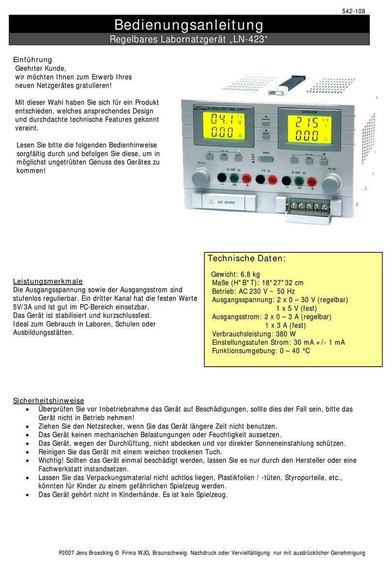
Funktionselemente:
1. Typenschild.
2. Digitale Anzeige der aktuellen Ausgangsstromstärke von Kanal 1.
3. Digitale Anzeige der aktuellen Ausgangsspannung von Kanal 1.
4. Digitale Anzeige der aktuellen Ausgangsstromstärke von Kanal 2.
5. Digitale Anzeige der aktuellen Ausgangsspannung von Kanal 2.
6. AMPERE: Regler für die Ausgangsstromstärke von Kanal 1.
7. VOLT: Regler für die Ausgangsspannung von Kanal 1.
8. SERIELL/EINZELN/PARALLEL: Umschalter, der die Beziehung von Kanal 1 und 2 zueinander festlegt.
9. AMPERE: Regler für die Ausgangsstromstärke von Kanal 2.
10. VOLT: Regler für die Ausgangsspannung von Kanal 2.
11. AN/AUS: Ein-/Aus-Schalter.
12. I+: Anschlussterminal. Positiver Ausgang von Kanal 1. Sicherheitsbuchse.
13. I MASSE: Anschlussterminal. Schutzleiteranschluss von Kanal 1. Sicherheitsbuchse.
14. I-: Anschlussterminal. Negativer Ausgang von Kanal 1. Sicherheitsbuchse.
15. II+: Anschlussterminal. Positiver Ausgang von Kanal 2. Sicherheitsbuchse.
16. II MASSE: Anschlussterminal. Schutzleiteranschluss von Kanal 2. Sicherheitsbuchse.
17. II-: Anschlussterminal. Negativer Ausgang von Kanal 2. Sicherheitsbuchse.
18. III+: Anschlussterminal. Positiver Ausgang von Kanal 3. Sicherheitsbuchse.
19. III-: Anschlussterminal. Negativer Ausgang von Kanal 3. Sicherheitsbuchse.
Die grünen LEDs SPANNUNG bzw. die roten LEDs STROM zeigen an, dass auf dem zugeordneten Kanal eine
Konstantspannung (C.V.) bzw. ein Konstantstrom (C.C.) herrscht.

542-306
P2009 Jens Broecking © Firma WJG, Braunschweig. Nachdruck oder Vervielfältigung nur mit ausdrücklicher Genehmigung
Betrieb:
•Schließen Sie das Gerät an eine Steckdose.
•Schalten Sie das Gerät mit AN/AUS [11] an.
•Stellen Sie die gewünschte Ausgangsspannung und den gewünschten Ausgangsstrom mit Hilfe von
VOLT [7] & [10] und AMPERE [6] & [9] ein. Die jeweils aktuellen Werte kann man auf den Displays [2]
bis [5] ablesen.
•Ein Verbraucher, der eine konstante Stromstärke von 3 A benötigt, kann am Terminal von Kanal 3
angeschlossen werden.
•Schließen Sie den gewünschten Verbraucher an die Anschlussterminals + und – an.
•Will man die Restwelligkeit reduzieren, muss man zusätzlich entweder + oder – mit MASSE [13] & [16]
verbinden.
•Die beiden regulierbaren Kanäle 1 & 2 können nun durch entprechenden Stellung von
SERIELL/EINZELN/PARALLEL [8] in Reihe, als auch parallel geschaltet werden. Dies führt im ersteren
Fall zur Spannungs- und im letzteren Fall zur Stromstärkenaddition. In beiden Fallen muss der
Verbraucher mit dem Pluspol an Buchse [12] und mit dem Minuspol an Buchse [17] angeschlossen
werden.
Einstellung einer konstanten Spannung (C.V.) auf Kanal 1 und Kanal 2:
•Drehen Sie AMPERE [6] & [9] im Uhrzeigersinn bis zum Anschlag.
•Drehen Sie VOLT [7] & [10] gegen den Uhrzeigersinn bis zum Anschlag.
•Schalten Sie das Gerät mit AN/AUS [11] ein.
•Nun sollte die grünen LEDs SPANNUNG leuchten.
•Stellen Sie nun mit VOLT [7] & [10] und mit Hilfe der Displays [3] & [5] die gewünschte
Ausgangsspannung pro Kanal ein.
•Schließen Sie die Verbraucher an das Terminal der gewünschten Kanäle an.
{Wird der Verbraucher nur am Ausgang eines Kanals angeschlossen, sind auch nur dessen Funtionen
einzustellen.}
Einstellung einer konstanten Stromstärke (C.C.) auf Kanal 1 und Kanal 2:
•Drehen Sie AMPERE [6] & [9] im Uhrzeigersinn bis zum Anschlag.
•Drehen Sie VOLT [7] & [10] gegen den Uhrzeigersinn bis zum Anschlag.
•Schalten Sie das Gerät mit AN/AUS [3] ein.
•Nun sollte die grünen LEDs SPANNUNG leuchten.
•Schließen Sie die Ausgangsterminals der beiden Kanäle kurz durch Verbinden der Plusbuchse [12] mit
der Minusbuchse [14] und der Plusbuchse [15] mit der Minusbuchse [17] .
•Drehen Sie VOLT [7] & [10] im Uhrzeigersinn bis die rote LEDs STROM anzeigen.
•Drehen Sie nun AMPERE [6] & [9] gegen den Uhrzeigersinn bis die gewünschte maximale
Ausgangsstromstärke pro Kanal auf den Displays [2] & [4] angezeigt wird.
•Entfernen Sie das jeweils kurzschließende Element von den Ausgangsbuchsen.
•Schließen Sie die Verbraucher an das Terminal der gewünschten Kanäle an.
•Ändern Sie keinesfalls die Stromstärke solange die Verbraucher noch angeschlossen sind.
{Wird der Verbraucher nur am Ausgang eines Kanals angeschlossen, sind auch nur dessen Funtionen
einzustellen.}

542-306
P2009 Jens Broecking © Firma WJG, Braunschweig. Nachdruck oder Vervielfältigung nur mit ausdrücklicher Genehmigung
Technical Specifications:
Weight: 8.0 kg
Measurement (H*B*T): 160*360*260 mm
Safety Connectors: 4 mm
Operation: AC 230 V ~ 50 Hz
Input Current: max. 3A
Output Voltage: 2x 0 – 30 V (adjustable)
1 x 5 V (fixed)
Output Current: 2x 0 – 3 A (adjustable)
1 x 3 A (fixed)
Ripple Voltage: ≤1mVrms
Function Environment: (5 – 40)°C & 90%RH
Reference Manual
Regulated Power Supply McPower „LAB-2303“
Preface
Dear Customer,
we like to congratulate you on the
purchase of your new power supply!
You have chosen a product which
combines deliberate technical features
with an appealing design.
Please read this manual conscientiously
and carry out the given instructions before
and while you are using your new device.
Capability Characteristics
The output voltage and the output current are
continuously adjustable.
The device is stabilized and short circuit proof.
Ideal for usage in laboratories, schools and training
centers.
Security Advices
•Before using the device, please check it for any possible damages. In case of damage do not operate it.
•Unplug the device if you do not use it for a certain time.
•The device may not become subject of mechanical stress and should not be exposed to humidity.
•To be considerate of the ventilation do not cover the device and protect it from direct solar radiation.
•Clean the device with a dry and soft cloth only.
•Caution! Should the device itself get damaged, please let the repair to the manufacturer or to a qualified
service agent.
•Please dispose packaging materials properly and do not let play children with it.
•The device itself is no toy either. Do not let children play with it too.

542-306
P2009 Jens Broecking © Firma WJG, Braunschweig. Nachdruck oder Vervielfältigung nur mit ausdrücklicher Genehmigung
Function Elements:
1. Type plate.
2. Digital display of the effective output current of channel 1.
3. Digital display of the effective output voltage of channel 1.
4. Digital display of the effective output current of channel 2.
5. Digital display of the effective output voltage of channel 2.
6. AMPERE: Rotary switch for the output current of channel 1.
7. VOLT: Rotary switch for the output voltage of channel.
8. SERIELL/EINZELN/PARALLEL: Toggle for adjusting the correlation of channel 1 and channel 2. Either IN
SERIES or SINGLE or PARALLEL.
9. AMPERE: Rotary switch for the output current of channel 2.
10. VOLT: Rotary switch for the output voltage of channel 2.
11. AN/AUS: On-/Off-switch.
12. I+: Terminal. Positive outlet of channel 1. Safety nut.
13. I MASSE: Terminal. Grounding of channel 1. Safety nut.
14. I-: Terminal. Negative output of channel 1. Safety nut.
15. II+: Terminal. Positive outlet of channel 2. Safety nut.
16. II MASSE: Terminal. Grounding of channel 2. Safety nut.
17. II-: Terminal. Negative output of channel 2. Safety nut.
18. III+: Terminal. Positive outlet of channel 3. Safety nut.
19. III-: Terminal. Negative output of channel 3. Safety nut.
The green LEDs SPANNUNG respectively the red LEDs STROM are showing that there is a constant voltage
respectively a constant current on the related channel.

542-306
P2009 Jens Broecking © Firma WJG, Braunschweig. Nachdruck oder Vervielfältigung nur mit ausdrücklicher Genehmigung
Operation:
•Connect the device to an electric outlet.
•Switch the device on with AN/AUS [11] .
•Adjust the desired output voltage and the desired output current with VOLT [7] & [10] und AMPERE [6]
& [9]. In each case the effective values are shown on the displays [2] to [5].
•A load which used a constant current of 3 A can be connected to the terminal of channel 3.
•Connect the desired load to the jacks of the terminals + and – an.
•To decrease the ripple voltage connect either + or – to MASSE [13] & [16] additionally.
•The two full adjustable channels 1 & 2 can be connected serial or parallel by setting
SERIELL/EINZELN/PARALLEL [8]. In the first case the voltage of both channels will be add together
while in the last case the current of both channels will be add together. In both cases the positive pole
of the load must be connected to jack [12] and its negative pole to jack [17].
Adjustment of a Constant Voltage (C.V.) on Channel 1 and 2:
•Turn AMPERE [6] & [9] clockwise up to the stop.
•Turn VOLT [7] & [10] counter clockwise to the stop.
•Switch the device on with AN/AUS [11].
•Now the green LEDs SPANNUNG should show.
•Now adjust the desired output voltage with VOLT [7] & [10] and the help of the displays [3] & [5].
•Connect the load to the desired terminals of this device.
{If the load only use the terminal of one channel only its functions has to be set up.}
Adjustment of a Constant Current (C.C.) on Channel 1 and 2:
•Turn AMPERE [6] & [9] clockwise up to the stop.
•Turn VOLT [7] & [10] counter clockwise to the stop.
•Switch the device on with AN/AUS [11].
•Now the green LEDs SPANNUNG should show.
•Short circuit the terminals by connecting the jack [12] with [14] and the jack [15] with [17].
•Turn VOLT [7] & [10] clockwise until the red LEDs STROM show.
•Turn AMPERE [6] & [9] counter clockwise until the displays [2] & [4] show the desired maximum output
currents.
•Removing the wires from the terminals to end the short circuits.
•Connect the load to the desired terminals of this device.
•Do not change the value of the output currents as long as the load is connected.
{If the load only use the terminal of one channel only its functions has to be set up.}
This manual suits for next models
1
Table of contents
Languages:
Other McPower Power Supply manuals
Popular Power Supply manuals by other brands

Kenwood
Kenwood pds20-18 Service manual

Agilent Technologies
Agilent Technologies 6023A operating manual

Pulsar
Pulsar PSU-B-13,8V/S-5A/1/EL-TR-17Ah/MC quick start guide

Thermal Dynamics
Thermal Dynamics Pak Master 75XL Plus Service manual

Nortel
Nortel Passport 8600 Series Installation

myGekko
myGekko GEK.EBU.TAS.0401 installation guide