MDL POWERUP T160 User manual

Page 2
ASSEMBLY INFORMATION
Due to pallet size restrictions, there are some bolts that require locating and
tightening upon arrival.
Bolt (x1) marked with RED arrow requires positioning through the ram eyelet
and securing.
Bolts (x4) marked with BLUE arrows (trimmer bar bracket) require installing
and securing.

Page 3
GENERAL INFORMATION
Read this manual before fitting or operating the machine. Whenever any doubt exists
contact your dealer or the MDL Service Department for assistance.
NOISE
The equivalent daily personal noise exposure from this machine, measured at the
operators’ ear, is within the range 78 – 85 DB. These figures apply to a normal
distribution of use where the noise fluctuates between zero and maximum. The
figures assume that the machine is fitted to a tractor with a quiet cab with the
windows closed in a generally open environment. We recommend that the windows
are kept closed. With the cab rear window open the equivalent daily personal noise
exposure will increase to a figure within the range 82 –88 DB. At equivalent daily
noise exposure levels of between 85 and 90 DB, ear protection is recommended, it
should be used if any window is left open.

Page 4
SAFETY INSTRUCTIONS
Before operating your machine, please read the following
safety instructions. Failure to comply with these warnings
may result in serious injury or death.
Please review these safety instructions with all users annually.
SIGNAL WORDS: The signal words DANGER, WARNING and CAUTION are used
with the safety messages in this manual and with each safety sign. They are defined
as follows:
DANGER: Indicates an immediate hazardous situation that, if not avoided, could result
in serious injury or death. This signal word is to be limited to the most extreme
situations typically for machine components that, for functional purposes, cannot be
guarded.
WARNING: Indicates a potentially hazardous situation that, if not avoided, could result
in serious injury or death, and includes hazards that are exposed when guards are
removed. It may also be used to alert against unsafe practices.
CAUTION: Indicates a potentially hazardous situation that, if not avoided, may result
in minor or moderate injury. It may also be used to alert against unsafe practice.

Page 5
SAFETY INFORMATION
This machine has the potential to be extremely dangerous, in the wrong hands it can
kill or maim. It is therefore imperative that the owner, and the operator of this machine,
read the following section to ensure that they are both fully aware of the dangers that
do, or may exist, and their responsibilities surrounding its use.
The operator of this machine is responsible not only for their own safety but equally
for the safety of others who may come into the close proximity of the machine, as the
owner you are responsible for both.
POTENTIAL SIGNIFICANT DANGERS ASSOCIATED WITH THE USE OF THIS
MACHINE:
●
Being hit by debris thrown by rotating components.
●
Being hit by machine parts ejected through damage during use.
●
Being caught on a rotating power take-off (PTO) shaft.
●
Being caught in other moving parts i.e.: belts, pulleys and cutting heads.
●
Electrocution from Overhead Power Lines (by contact with or ‘flashover’ from).
●
Being hit by cutting heads or machine arms as they move.
●
Becoming trapped between tractor and machine when hitching or unhitching.
●
Tractor overbalancing when machine arm is extended.
●
Injection of high-pressure oil from hydraulic hoses or couplings.
●
Machine overbalancing when freestanding (out of use).
●
Road traffic accidents due to collision or debris on the road.
BEFORE USING THIS MACHINE, YOU MUST:
●
Ensure you read all sections of the operator handbook.
●
Ensure the operator is, or has been, properly trained to use the machine.
●
Ensure the operator has been issued with and reads the operator handbook.

Page 6
●
Ensure the operator understands and follows the instructions in operator
handbook.
●
Ensure the tractor front, rear and side(s) are fitted with metal mesh or
polycarbonate guards of suitable size and strength to protect the operator
against thrown debris or parts.
●
Ensure tractor guards are fitted correctly, are undamaged and kept properly
maintained.
●
Ensure that all machine guards are in position, are undamaged, and are kept
maintained in accordance with the manufacturer’s recommendations.
●
Ensure blades and their fixings are of a type recommended by the
manufacturer, are securely attached and that none are missing ordamaged.
●
Ensure hydraulic pipes are carefully and correctly routed to avoid damage by
chaffing, stretching or pinching and that they are held in place with the correct
fittings.
●
Always follow the manufacturer’s instructions for attachment and removal of the
machine from the tractor.
●
Check that the machine fittings and couplings are in good condition.
●
Ensure the tractor meets the minimum weight recommendations of the machine
manufacturer and that ballast is used as necessary.
●
Always inspect the work area thoroughly before starting to note obstacles and
remove wire, bottles, cans and other debris.
●
Use clear suitably sized warning signs to alert others to the nature of the
machine working within that area. Signs should be placed at both ends of the
work site. (It is recommended that signs used are of a size and type specified
by the Department of Transport and positioned in accordance with their and the
Local Highways Authority guidelines).
●
Ensure the operator is protected from noise. Ear defenders should be worn and
tractor cab doors and windows must be kept closed. Machine controls should
be routed through proprietary openings in the cab to enable all windows to be
shut fully.

Page 7
●
Always work at a safe speed taking account of the conditions i.e.: terrain,
highway proximity and obstacles around and above the machine.
●
Extra special attention should be applied to Overhead Power Lines. Some of
our machines are capable of reach in excess of 8 metres (26 feet) this means
they have the potential to well exceed, by possibly 3 metres (9’ 9”), the lowest
legal minimum height of 5.2 metres from the ground for 11,000- and 33,000-
volt power lines. It cannot be stressed enough the dangers that surround this
capability, it is therefore vital that the operator is fully aware of the maximum
height and reach of the machine, and that they are fully conversant with all
aspects regarding the safe minimum distances that apply when working with
machines in close proximity to Power Lines. (Further information on this subject
can be obtained from the Health & Safety Executive or your Local Power
Company).
●
Always disengage the machine, kill the tractor engine, remove and retain the
key before dismounting for any reason.
●
Always clear up all debris left at the work area; it may cause hazard to others.
●
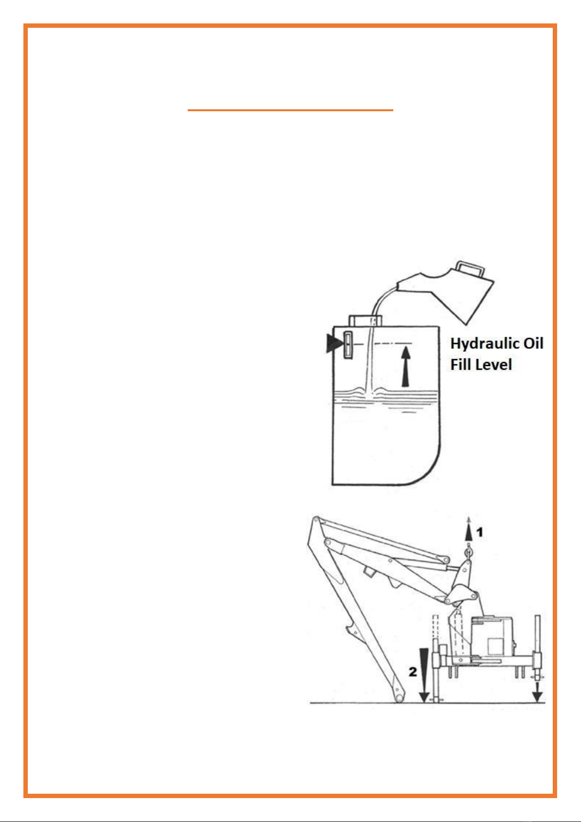
Always ensure when you remove your machine from the tractor that it is left in
a safe and stable position using the stands and props provided and secured if
necessary.
●
Beaware of the articulated arms when adjusting towards the limitsof their travel
-
in certain positions, arms could make contact with hydraulic ram components
and cause damage to the machine.
WHEN NOT TO USE THIS MACHINE:
●
Never attempt to use this machine if you have not been trained to do so.
●
Never use a machine until you have read and understood the operator
handbook, are familiar with, and practiced the controls.
●
Never use a machine that is poorly maintained.
●
Never use a machine if guards are missing or damaged.

Page 8
●
Never use a machine on which the hydraulic system shows signs of wear or
damage.
●
Never fit, or use, a machine on a tractor that does not meet the manufacturer’s
minimum specification level.
●
Never use the machine if the tractor cab guarding is damaged, deterioratingor
badly fitted.
●
Never turn a machine cutting head to an angle that causes debris to be ejected
towards the cab.
●
Never start or continue to work a machine if people are nearby or approaching
-
Stop and wait until they are at a safe distance before continuing. WARNING:
Some Cutting Heads may continue to ‘freewheel’ for up to 40 seconds after
being stopped.
●
Never attempt to use a machine on materials in excess of its capability.
●
Never use a machine to perform a task it has not been designed to do.
●
Never operate the tractor or machine controls from any position other than from
the driving seat, especially whilst hitching or unhitching the machine.
●
Never carry out maintenance of a machine or a tractor whilst the engine is
running –the engine should be switched off, the key removed and pocketed.
●
Never leave a machine unattended in a raised position –it should be lowered
to the ground in a safe position on a level firm site.
●
Never leave a tractor with the key in or the engine running.
●
Never carry out maintenance on any part or component of a machine that is
raised unless that part or component has been properly substantially braced or
supported.
●
Never attempt to detect a hydraulic leak with your hand –use a piece of
cardboard.
●
Never allow children near to, or play on, a tractor or machine under any
circumstances.

Page 9
INITIAL ATTACHMENT TO TRACTOR
The machine will be delivered in a partially dismantled condition,
secured with transport strap and banding.
•
Choose a firm level site.
•
Remove any transport straps,
banding straps and loose items
•Raise the machine using overhead
lifting equipment with a minimum
capacity of 1500kg SWL.
LEAVE IN POSITION AT THIS STAGE.
Lower the legs and pin in position
selecting the holes that position the
machines gearbox stub shaft approx.
75 mm below the tractors P.T.O. shaft.
Note: Leg pin position used.

Page 10
TRACTOR ATTACHMENT
Reverse tractor squarely into position
adjacent to the machine and connect
the linkages to the machine as shown:
Correct linkage setup as shown above
WARNING!
The quadrant lever or machine
controls must only be operated from
the tractor seat. Ensure no one is
standing close to or within the linkage
arms or bars.
Make adjustments as necessary to
align the machine 90°:

Page 11
NOTE:
Be aware - as lift occurs, the
machinery may tilt slightly.
Measure PTO shaft and cut to dimension
shown (distance ‘A’ minus 75mm) –
see diagram opposite and refer to
maintenance section for further details.
NOTE:
For subsequent use on a different tractor
measure again - there must be a minimum
of 6" (150mm) of shaft overlap
Fit PTO shaft into position.
Attach the torque chains to a convenient
location to prevent rotation of the shaft
guards.

Page 12
Fit machine controls into the cab
Request assistance.
Operate 'Lift up' on machine controls only as much as sufficiently required to enable access
to the stand legs to retract them.
Raise the stand legs into the work position and secure with their pins - see diagram
opposite.
Tighten check chains and/or stabilizer bars.
The machine should now be carefully operated throughout its full range of movements to
check hoses are not being strained, pinched, chafed or kinked, and that all movements are
functioning correctly.

Page 13
The machine can now be folded into the transport position ready to proceed to the work site
- Refer to the section on Transport
Position for details on this subject.
REMOVAL FROM TRACTOR
Select a firm safe site to remove the machine.
Locate parking legs into their housings.
NOTE: The correct, and most stable, position for removing the machine from the
tractor is with the arm positioned to the rear of the machine.
•Position the cutting head on the ground directly to the rear of the machine at
approximately half reach.
•Disengage PTO.
•Remove latch security pins.
•Locate parking legs into their housings.
•Take machine weight on draft links sufficient only to allow the top link to be
disconnected.
•Open axle catches using the release cord and lower the machine.
•Disconnect draft links and remove the PTO shaft.
•Remove the axle catches from the tractor.
•Remove control units from the tractor cab and stow clear of the ground in a location
where they are protected from the weather
•or risk of accidental damage.
•Drive tractor away from machine.
•Replace check chains / stabiliser bars
STORAGE
When not in use, some cylinder ‘drift’ may occur after time, where the hydraulic rams
may shift downward under the machines own weight. This ‘drifting’ occurrence is
normal, and considerations should be taken to avoid any damage should this occur
while not in use. With this in mind, it may be advisable to store the machine with the
cutting bar ‘parked’ on the ground to minimize any movements.
If the machine is to be left standing for extended periods of time, lightly coat the
exposed portions of the ram rods with grease. Subsequently this grease should be
wiped off before the rams are next moved. If the machine is to be stored outside tie a
piece of tarpaulin or canvas over the control assembly –
do not use a plastic bag as this can lead to corrosion in the unit.
HYDRAULIC SYSTEM

Page 14
OIL SUPPLY
Check the oil level in the reservoir daily.
No fixed time period can be quoted for oil changes as operating conditions and
maintenance standards vary so widely. Burnt and scorched oil odours and the oil
darkening and thickening are all signs of oxidation and indicate the oil should be
changed.
Moisture that results from condensation can become entrapped in the oil and cannot
be removed by filtration so that water contamination is progressive.
Contamination can be reduced by:
•
Cleaning around the reservoir cap before removal, and keeping that area clean.
•
Using clean containers when replenishing the system.
•
Regular servicing of the filtration system.
FILTRATION MAINTENANCE
The machine is protected by a 125-micron suction strainer and a low pressure 10-
micron full flow return line filter.
•
Suction strainer
The strainer is permanently fixed within the reservoir.
Should symptoms of pump cavitation or spongy intermittent operation occur the
tank must be drained and flushed out with a suitable cleaning agent e.g. clean
diesel oil
•
Return Line Filter
The elements should be changed after the first 50 hours and thereafter at 500-hour
intervals. It is important to note hours worked as if the filter becomes blocked an
internal by-pass within the canister will operate and no symptoms of filter malfunction
will occur to jog your memory.
HYDRAULIC HOSES
The condition of all hoses should be carefully checked during routine service of
the machine. Hoses that have been chaffed or damaged on their outer casing
should be securely wrapped with waterproof adhesive tape to stop the metal

Page 15
braid from rusting. Hoses that have suffered damage to the metal braid should
be changed at the earliest opportunity.
HOSE REPLACEMENT
•
Replace one hose at a time to avoid the risk of wrong connections.
•
When the hose is screwed to an additional fitting or union, use a second
spanner on the union to avoid breaking both seals.
•
Do not use jointing compound on the threads.
•
Avoid twisting the hose. Adjust the hose line to ensure freedom from
rubbing or trapping before tightening hose end connections.
Before changing hoses study the installation these are carefully calculated to prevent
hose
damage during operation. Always replace hoses in exactly the same manner. This
is especially important for the cutter hoses where they must be crossed, upper to
lower, at the dipper and head pivots.
SAFETY NOTE
Soft Seal hose connections are capable of holding pressure when the nut is only
‘finger tight’. It is therefore recommended that when dismantling, the hose be
manually flexed, to relieve any residual pressure, with the retaining nut slackened
prior to complete disassembly.

Page 16
TRACTOR ATTACHMENT –Linkage Mounted Machines

Page 17

Page 18

Page 19

Page 20
Table of contents
Other MDL POWERUP Trimmer manuals