© 2014 MDM INC.
Corrosion-resistant, non-metallic pumps.
© 2014 MDM INC.
Corrosion-resistant, non-metallic pumps.
© 2014 MDM INC.
Corrosion-resistant, non-metallic pumps.
Proudly Made in the USA Proudly Made in the USA
INSTALLATION
Please read carefully! When properly installed the Advance 4000 will provide dependable trouble-free service.
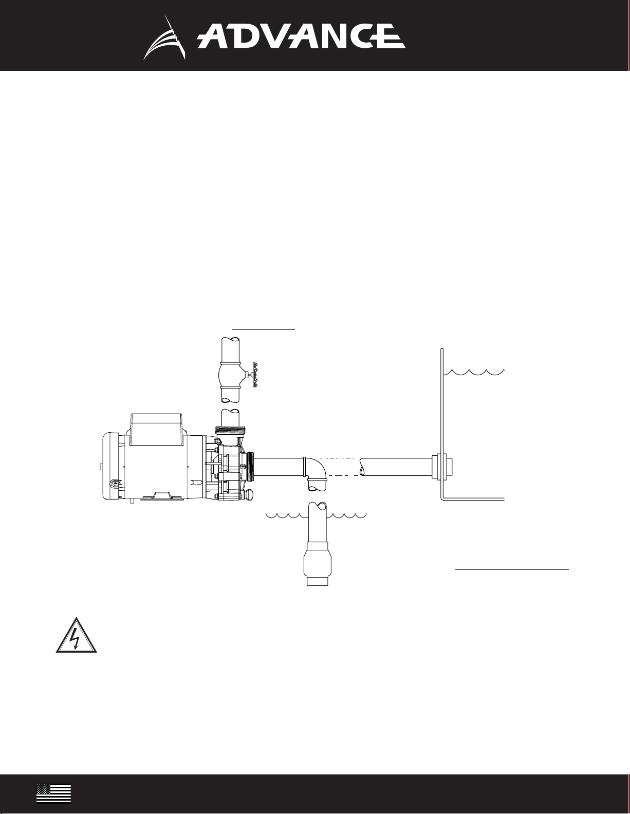
1. Locate the pump as near the water source as possible. A flooded suction situation is preferred. The pump is not self-priming, therefore, if the fluid level is
below the pump, a swing check valve must be installed and the pump primed prior to start-up. (Figure 2)
2. Mount motor base to a secure, immobile foundation.
3. Use only plastic fittings on both the intake and discharge ports. Seal pipe connections with Teflon™ paste. These fittings should be self-supported and in neutral
alignment with each port. (i.e. Fittings must not be forced into alignment which may cause premature line failure or damage to the pump volute.) For non-flooded
installations, a strainer basket and check valve are recommended.
4. Never restrict the intake. Keep both input and discharge lines as free of elbows and valves as possible. Always use pipe of adequate diameter. This will reduce
friction losses and maximize output.
5. The Advance 4000 is not self-priming! It must not be run dry! We recommend a flooded suction installation. Please read carefully! When properly installed, the
Advance 4000 will provide dependable, trouble-free service.
6. For additional plumbing tips, review MDM’s website: www.mdminc.com for pond plumbing and pump installation hints.
ELECTRICAL HOOK-UP
1. Check that supply voltages match the motor’s requirements.
2. Check motor wiring and connect, according to instructions on motor, to match supply voltage.
3. Power cord should be protected by conduit or by cable and be of proper gauge. It should be no longer than necessary.
4. Power should be drawn directly from a box with circuit breaker protection or with a fused disconnect switch.
PUMP END ASSEMBLY
1. Clean and inspect all pump parts (0-ring, seal seats, motor shaft, etc.).
2. Apply sealant to the bracket bore ID wall and around the seal case - follow sealant mfg. instructions. We recommend using Gasgacinch®. Silicone
sealant can also be used.
3. Press carbon graphite seal into bracket while taking care not to damage carbon graphite face.
4. Place slinger (rubber washer) over motor shaft and mount bracket to motor.
5. Carefully, lubricate the seal seat elastomer OD and impeller hub ID with water. Press the seal seat into the impeller hub making certain that the ceramic is in
evenly - the sealing surface should be parallel with the impeller hub.
6. Carefully lubricate carbon-graphite and ceramic sealing surfaces with CLEAN water. Do not use silicon lubricants or grease!
7. Assemble Bracket to motor with four M-bolts
8. Thread impeller onto shaft and tighten! If required, remove motor end-cap and use a screwdriver on the back of motor shaft to prevent shaft
rotation while tightening. Replace motor end cap.
9. Seat large O-ring in volute slot and assemble volute to bracket with seven 1/4-20 x 2 3/4” hex cap screws, washers and nuts. Tighten in a cross pattern (30 in-lbf).
10. Install drain plug with its O-ring in volute drain hole.
11. Before operating pump, allow a proper cure time for the sealant used in step 2.
DISASSEMBLY
1. Shut off power to motor before disconnecting any electrical wiring from the back of the motor.
2. Disassemble volute from bracket by removing the seven 1/4” - 20 threads per inch x 2 3/4” hex cap screws.
3. Remove cap covering shaft at back of motor and with a large screwdriver, prevent shaft rotation while unscrewing impeller.
4. Remove ceramic piece from impeller. (If you are replacing the seal)
5. Detach bracket from motor.
6. Remove carbon-graphite seal from bracket by pressing out from the back. Do not dig out from the front! (If you are replacing the seal)
We congratulate you on your choice of the Advance 4000 Centrifugal Pump! It has been carefully designed using the advantages of today’s technology and
carefully constructed to give you the dependability of yesterday. To insure proper performance, we urge you to carefully follow the instructions in this manual.
If you have any questions, call your nearest distributor or M.D.M. for assistance.
PUMP
SWING CHECK VALVE
FLOODED SUCTION
WARNING: DO NOT RUN DRY!
WARNING: ALWAYS SHUT OFF ELECTRICAL POWER BEFORE INSTALLATION AND / OR SERVICING THIS PUMP! ALL ELECTRICAL WIRING SHOULD MEET
STATE AND LOCAL ORDINANCES. IMPROPER WIRING MAY NOT ONLY BE A SAFETY HAZARD BUT MAY PERMANENTLY DAMAGE THE MOTOR AND/OR
PUMP! 230V 50 HZ MOTORS AVAILABLE - CONTACT YOUR SUPPLIER FOR INFORMATION.
BALL VALVE
(Figure 2)
SUCTION LIFT
*Motor illustration is for reference only.
2.75 2.43
3.50
4.22
4000 4000
NUMBER DESCRIPTION
01 SLINGER
02 M-BOLT
03 BRACKET
04 MECHANICAL SEAL
05 IMPELLER
06 VOLUTE O-RING
07 VOLUTE
8, 9, 10 HARDWARE KIT
11 DRAIN PLUG & O-RING
ADVANCE 4000
5
7
4
3
11
1
2
6
9
8
8
10