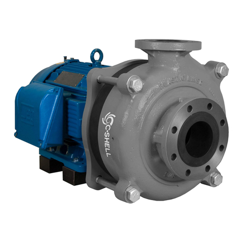
MDM C-Shell 4X3-10 Manual

© MDM INCORPORATED
WWW.MDMINC.COM
PROUDLY MADE
IN THE USA Generated from efficiency. Adapted for flow. Built for longevity.
4X3 GENERAL ASSEMBLY
®
4X3 INSTALLATION AND SERVICE MANUAL
Read completely before you install or operate your new pump. Do not allow the motor to become submerged.
Never run dry. Never reverse rotation. Never exceed an internal case pressure of: 100 PSI.
S/N: XXXX-XXXXXX
XXXXXXXXX
®
P.1
FILL IN FOR FUTURE REFERENCE:
MODEL: ______________________________
SERIALNUMBER:_______________________
DATEPURCHASED: ______________________
TO REGISTER YOUR PUMP
SCAN THIS QR CODE OR VISIT
MDMINC.COM/PUMP-REGISTRATION

© MDM INCORPORATED
WWW.MDMINC.COM
PROUDLY MADE
IN THE USA Generated from efficiency. Adapted for flow. Built for longevity.
4X3 GENERAL ASSEMBLY
®
WARNING: Eye protection is strongly recommended
We congratulate you on your choice of the C•Shell® 4X3 Centrifugal Pump. It has been carefully designed using the advantages of today’s technology
and meticulously constructed to give you the dependability of yesterday. To insure proper performance and longevity, we urge you to follow the
instructions in this manual. If you have any questions, contact MDM Incorporated for assistance.
PRIOR TO INSTALLATION
The instructions below should only be followed if the pumps are placed in storage.
1. Once received from factory, store all crated pumps in a dry and covered location.
2. Make certain all uncoated machined surfaces are coated with a dielectric or marine grease every seven days to prevent oxidation.
3. Rotate motor shaft multiple times once a week.
INSTALLATION
1. Locate the pump as near the fluid source as possible. We recommend a flooded suction installation.
2. Mount motor base to a secure, immobile foundation.
3. The pipe fittings should be self-supported and in neutral alignment with each port. The fittings must not be forced into alignment which may
cause premature line failure or damage to the pump volute.
4. Never restrict the intake. Keep both input and discharge lines as free of elbows and valves as possible i.e. five feet per second max and a straight
run of at least 10 pipe diameters on the suction side. This will reduce friction losses and maximize output.
5. The C•Shell®Pump is not self-priming. It must not be run dry.
ELECTRICAL HOOK-UP
1. Check that supply voltages match the motor’s requirements. The supply voltages can be found on the motor nameplate.
2. Verify that the internal motor leads (load-side) are connected according to the specifications shown on the motor nameplate and that they
match the supply voltage (line-side).
3. Verify motor rotation with rotation meter. Incorrect rotation can cause serious damage to pump and/or motor. MDM Incorporated does not
recommend checking rotation by quickly switching power on and off because serious damage can occur.
4. Supply power wiring (load side) should be protected by conduit or by cable and be of proper gauge. Length should be no longer than necessary.
5. Power should be drawn directly from an enclosure with circuit breaker protection or with a fused disconnect switch.
PUMP END ASSEMBLY/DISASSEMBLY
Contact a factory authorized agent, service center, or factory directly before disassembly or assembly. MDM Incorporated factory hours are 7:30am -
4pm MST, Monday through Friday. You can reach us toll free at (719) 634-8202 or e-mail us at [email protected].
P.2
WARNING: ALWAYS SHUT OFF ELECTRICAL POWER BEFORE INSTALLATION AND / OR SERVICING THIS PUMP!
ALL ELECTRICAL WIRING SHOULD MEET STATE AND LOCAL ORDINANCES. IMPROPER WIRING MAY NOT ONLY BE A SAFETY HAZARD BUT MAY
PERMANENTLY DAMAGE THE MOTOR AND/OR PUMP! 50 HZ MOTORS AVAILABLE - CONTACT YOUR SUPPLIER FOR INFORMATION.

© MDM INCORPORATED
WWW.MDMINC.COM
PROUDLY MADE
IN THE USA Generated from efficiency. Adapted for flow. Built for longevity.
4X3 GENERAL ASSEMBLY
®
C•SHELL®4X3 ASSEMBLY INSTRUCTIONS
I. EQUIPMENT & SUPPLIES REQUIRED
The C•Shell®pump series have pump-motor unit gross weights up to 800lbs. It is highly recommended an experienced pump mechanic or millwright
perform any assembly or disassembly required. Failing to properly handle and install the pump components may result in damage and will void the
factory warranty. When performing any assembly or disassembly of the pump-end components, please make certain the proper equipment and
supplies required are present for all service and maintenance work.
A. Safety glasses
B. Latex/Rubber Gloves (for working with fasteners, elastomers, lubricants, and greases)
C. Safety Boots with Toe Protection
D. Rags
E. Lint Free Rags (McMaster-Carr p/n:7366T35)
F. Lint free Paper Dry Wipes (McMaster-Carr p/n: 7367T38)
G. Isopropyl Alcohol (McMaster-Carr p/n: 54845T42)
H. Anti-Seize Grease (McMaster-Carr reference p/n:1820K23)
I. Molykote®111 Silicon Based Dielectric Grease (McMaster-Carr reference p/n: 1204K32)
J. Socket Wrench Kit (up to 1-13/16” sockets)
K. Torque Wrench kit (up to 100 ft/lbs & up to ¾” driver)
L. 1 Ton Scissor Lift or Cart
M. 1 Ton Chain Hoist
N. 1 Ton Gantry System
0. 12” Adjustable C-Clamp
II. PUMP COMPONENTS IDENTIFICATION
Pump-End Exploded View
Review all components and make certain required items are on hand before performing the assembly steps.
III. PUMP END ASSEMBLY TO MOTOR
Motor Preparation
a. The entire C•Shell®pump is built onto the motor, so to begin assembly motor must be firmly secured to a work surface. The feet can be clamped
or bolted onto the surface to prevent movement or tipping. The motor’s mounting face should hang over the edge of the work surface so there is
no interference during assembly (See Figure 1). A smaller motor is more prone to tipping when the wet end is installed than a larger motor, but
all should be firmly secured.
b. Prepare motor by removing all stickers and wiping off excess lubricant from the shaft. Remove the Square Key (9) and fit the Shaft Sleeve (8)
over the motor shaft. Place the Square Key (9) into the motor shaft keyway along with the Shaft Sleeve (8) and cut the Square Key (9) stock so
that it does not protrude past the shoulder of the Shaft Sleeve (8). (See Figure 7 & 8).
c. Remove Square Key (9) and Shaft Sleeve (8) from shaft. Ensure there is a light application of anti-seize on the motor shaft.
d. Apply a light application of Anti-Seize (Item H) to front motor face/flange.
e. Apply a light application of Anti-Seize (Item H) to shaft.
P.3
FULL THREAD LENGTH ENGAGEMENT IS REQUIRED FOR ALL FASTENERS.
LIGHTLY LUBRICATE ALL SEAL O-RINGS TO PREVENT DAMAGE & HOLD O-RINGS IN PLACE DURING ASSEMBLY.

© MDM INCORPORATED
WWW.MDMINC.COM
PROUDLY MADE
IN THE USA Generated from efficiency. Adapted for flow. Built for longevity.
4X3 GENERAL ASSEMBLY
®
1. Bracket Plate
a. Attach Bracket Plate (2) to motor face using Hex or Allen Head Fasteners (3) per torque specs (See Table B) with the drain slot pointed downwards.
b. Anti-seize (Item H) should be applied to the register face and motor screws to aid in disassembly.
2. Seal Installation
a. Referencing seal manufacturer’s instructions, install Stationary Seal Face (7A) in the Seal Housing (4). Lightly lubricate outside rubber boot of
Stationary Seal Face (7A) with Molykote®111 Silicon Based Dielectric Grease (Item I) to ease assembly and press Stationary Seal Face (7A) into Seal
Housing (4) counterbore gently by hand. Warning: Hard tools can damage the seal face and prevent proper operation. Ensure seal is firmly seated in
Seal housing (4). Inspect from the front and back of Seal Housing (4) to make sure seal is straight and fully seated (Figures 2 and 3).
b. Clean stationary seal bore with isopropyl alcohol and a lint free paper dry wipe and Isopropyl Alcohol (Item G) until all contaminates wipe clean
and alcohol evaporates.
c. Insert Seal Housing (4) into register fit on Bracket Plate (2) being careful not to nick or scratch stationary seal with motor shaft. The Seal
Housing (4) will not be positively retained at this point, so use extreme caution to prevent damage to seal components. Use a bent metal strap
or a 12” adjustable C-Clamp (Item O) to hold the seal housing to the bracket plate. Example of retainer shown in (Figure 4).
d. Lubricate rubber inside of Rotary Seal Face (7B) with a very light coating of Molykote®111. Insert Shaft Sleeve (8) into Seal Spring (7C) and
Rotary Seal Face (7B) assembly with the Spring Retainer (7D) against the Shaft Sleeve (8) shoulder. See (Figures 5 & 6).
3. Shaft Sleeve Installation
a. Slide Shaft Sleeve (8) with seal components installed onto motor shaft with keyway aligned with key. The pentagonal side of the Shaft Sleeve (8) will
face away from the motor.
b. Seat Shaft Sleeve (8) firmly against the motor shaft shoulder. Ensure assembly will not fall off motor shaft.
c. Insert Square Key (9) into keyway and verify that the key does not protrude further than the Shaft Sleeve (8) shoulder. See (Figures 7 & 8).
4. Impeller Installation
a. Install Impeller (11) on the pentagonal side of the Shaft Sleeve (8).
b. Lightly lubricate Impeller Bolt O-Ring (17) with Molykote®111 Silicon Based Dielectric Grease (Item I) and fit into groove on Impeller Bolt (18).
c. Lightly lubricate Pentagon Hub O-Ring (13) with Molykote®111 Silicon Based Dielectric Grease (Item I) and fit into groove on Pentagon Hub (14).
d. Install Pentagon Hub Spacer (12), and Pentagon Hub (14) onto Shaft Sleeve (8) followed by Impeller Bolt (18), with Impeller Bolt Flat Washer (15)
and Impeller Bolt Lock Washer (16). Hold Pentagon Hub Spacer (12) relatively centered over the Shaft Sleeve (8). Tighten Impeller Bolt (18) with
an impact tool to avoid having to lock shaft. Verify that the Pentagon Hub Spacer (12) is centered.
e. If an impact tool is unavailable, motor fan cover and fan can be removed from the motor to access the shaft extension on the rear of the motor. This can
be held with a keyed shaft wrench (Table A) or an adjustable wrench while the shaft screw is tightened against it per torque specs (Table B).
5. Case (Volute) Installation
a. Fit Case (19) register over the Seal Housing (4) and insert Case Bolts (1C) through Case (19) and Bracket Plate (2).
b. For 4x3 and 6x5 pumps, fasten Case Nuts (1A) and Case Washers (1B) onto Case Bolts (1C) and torque according to the specifications found in (Table B).
c. For 3x2 pumps, torque Case Bolts (1C) according to the specifications found in (Table B).
6. Impeller Clearance Check
a. Verify rotation with minimal drag by hand. Some drag (i.e. soft scraping noise) is expected from Seal (7A-7D) and for the Impeller (11) to wear
into the Case (19). It may take a little torque to turn. If Impeller (11) is locked then tear back down and investigate.
b. Check clearance between Impeller (11) and Case (19) through discharge or suction openings. Ideal clearance is .020-.120”. A tighter clearance
will provide higher efficiencies and slightly higher head values. See chart below for net clearance changes with various Case Gasket (6) and
Impeller Spacer (10) combinations. Do not stack spacers or gaskets above 2 tall.
c. If clearance is too tight, remove Case (19) and insert the Case Gasket (6).
Reassemble and verify clearance.
d. If clearance is too loose, remove Case (19), Impeller Bolt (18), Pentagon
Hub (14), Pentagon Hub Spacer (12) and Impeller (11). Remove the Impeller
(11) and place Spacer Shim (10) on the Shaft Sleeve (8) to achieve desired
clearance. Reassemble from Step 5.
7. Case O-Ring
a. Once clearance is verified, lightly grease case Case O-Ring (5) and fit into groove on Seal Housing (4). This step is withheld until now to prevent
damage to Case O-Ring (5) if disassembly and reassembly is required.
8. Verify rotation and final clearance.
9. Proceed to Start Up.
SCENARIO NET CLEARANCE CHANGE
Standard: 1 gasket, 0 impeller spacer 0.000”
Add Case Gasket +0.032”
Remove Case Gasket -0.032”
P.6
IMPELLER CLEARANCE CHART

© MDM INCORPORATED
WWW.MDMINC.COM
PROUDLY MADE
IN THE USA Generated from efficiency. Adapted for flow. Built for longevity.
4X3 GENERAL ASSEMBLY
®
6 FLAT WASHER
7 LOCK WASHER
4 RISER BLOCK
3 THREADED ROD
2 MOTOR FOOT ANCHOR
1 ANCHOR INSTALLATION TOOL
8 HEX NUT
5 MOTOR SHIM*
CONCRETE PAD
C•SHELL®4x3 MOTOR ANCHOR INSTALLATION
Visit McMaster-Carr Supply Company at www.mcmaster.com to find parts
listed in the table below. Enter the McMaster part number in their search
engine to be directed to part page.
IMPORTANT: Make certain all
inlet and discharge piping are
independently supported to
a post base, strut, and pipe
clamp system.
NO. DESCRIPTION QTY.
B GROUP MOTORS
213/5JM
3/8-16
C GROUP MOTORS
254/6JM
1/2-13
D GROUP MOTORS
284/6JM
1/2-13
D GROUP MOTORS
324/6JM
5/8-11
1 ANCHOR INSTALLATION TOOL 1 97077A120 97077A130 97077A130 97077A140
2 MOTOR FOOT ANCHOR 4 97095A121 97095A131 97095A131 97095A141
3 THREADED ROD 4 90575A292 90575A736 90575A732 90575A810
4 RISER BLOCK 4 INCLUDED INCLUDED INCLUDED INCLUDED
5 MOTOR SHIM* (AS NEEDED) 4 94420A160 94420A160 94420A160 94420A160
6 FLAT WASHER 4 90107A127 90107A033 90107A033 90107A035
7 LOCK WASHER 4 92147A031 92147A033 92147A033 92147A035
8 HEX NUT 4 94819A049 94819A055 94819A055 94819A058
McMaster-Carr Part Numbers
Consult Motor Name Plate for Frame Size Specification
P.7

© MDM INCORPORATED
WWW.MDMINC.COM
PROUDLY MADE
IN THE USA Generated from efficiency. Adapted for flow. Built for longevity.
4X3 GENERAL ASSEMBLY
®
P.4
1C 201B19181716151412 139 1165 8421A 1B 3 7D7C7B7A 10
CONSULT MANUFACTURER FOR PARTS PRICING
*3. SCREW SIZE AND TYPE IS BASED ON MOTOR SIZE
*6. CASE GASKET (USE AS NEEDED)
7A-7D. SEAL ASSEMBLY SOLD AS A SET
*9. SQUARE KEY (COMES WITH MOTOR) - CONSULT FACTORY FOR PRICING AND REPLACEMENT
*10. SPACER SHIM (USE AS NEEDED)
*11. IMPELLER PART NUMBERS DIFFER BASED ON PERFORMANCE REQUIREMENTS
*20. MOUNTING BLOCK - CONSULT FACTORY FOR PRICING AND REPLACEMENT PARTS
*NUMBERS IN CIRCLES BELOW CORRESPOND
WITH STEPS IN ASSEMBLY INSTRUCTIONS.
C•SHELL®4X3 EXPLODED VIEW AND PARTS LIST
NO. PART NAME
MOTOR B (213-215JM)
PART NUMBER
MOTOR C (254-256JM)
PART NUMBER
MOTOR D (284-324JM)
PART NUMBER QT Y.
1A CASE NUTS HCS14144 HCS14144 HCS14144 4
1B CASE WASHERS FW14 FW14 FW14 8
1C CASE BOLTS HHN14 HHN14 HHN14 4
2BRACKET PLATE MD1401 MS MD1401 MS MD1402 MS 1
3 HEX OR ALLEN HEAD FASTENERS* HCS08012 HCS08012 HCS10016 4
4SEAL HOUSING MD1202 W35 MD1202 W35 MD1202 W35 1
5 CASE O-RING ARP277 ARP277 ARP277 1
6CASE GASKET* A0160FA A0160FA A0160FA 1
7A STATIONARY SEAL FACE 24170545 (CARBON GRAPHITE/
CERAMIC)
24170510 (SIC VS. SIC)
24170545 (CARBON GRAPHITE/
CERAMIC)
24170510 (SIC VS. SIC)
24170545 (CARBON GRAPHITE/
CERAMIC)
24170510 (SIC VS. SIC)
1
7B ROTATING SEAL FACE
7C SPRING
7D SPRING RETAINER
8SHAFT SLEEVE MD0905 316L MD0903 316L MD0903 316L 1
9 SQUARE KEY* CONSULT FACTORY CONSULT FACTORY CONSULT FACTORY 1
10 SPACER SHIM* MD2300 NYL MD2300 NYL MD2300 NYL 2
11 IMPELLER* CONSULT FACTORY CONSULT FACTORY CONSULT FACTORY 1
12 PENTAGON HUB SPACER MD0701 316L MD0702 316L MD0702 316L 1
13 PENTAGON HUB O-RING ARP126 ARP126 ARP126 1
14 PENTAGON HUB MD0600 316L MD0601 316L MD0601 316L 1
15 IMPELLER BOLT FLAT WASHER FW06 FW08 FW08 1
16 IMPELLER BOLT LOCK WASHER LW06 LW08 LW08 1
17 IMPELLER BOLT O-RING ARP010 ARP012 ARP012 1
18 IMPELLER BOLT MD0300 316S MD0301 316S MD0301 316S 1
19 CASE MD0101 W35 MD0101 W35 MD0101 W35 1
20 RISER BLOCK* CONSULT FACTORY CONSULT FACTORY CONSULT FACTORY 4

© MDM INCORPORATED
WWW.MDMINC.COM
PROUDLY MADE
IN THE USA Generated from efficiency. Adapted for flow. Built for longevity.
4X3 GENERAL ASSEMBLY
®
PARTS 3X2 4X3 6X5
Motor Bolts 50 50 50
Impeller Bolt 40 40 40
Case Bolts 32 65 65
TABLE B - BOLT TORQUE VALUES (ALL VALUES IN FT-LBS)
TABLE C - SHAFT WRENCH DIMENSION
TABLE A - SHAFT WRENCH
NOMINAL
SHAFT
DIAMETER
WX
(+.06)
Y
(+.015) Z
0.875 1.375 0.958 0.878 - 0.880 0.188 - 0.192
1.125 1.625 1.253 1.128 - 1.130 0.125 - 0.129
1.625 2.125 1.806 1.628 - 1.630 0.375 - 0.379
1.750 2.5 1.940 1.753 - 1.755 0.375 - 0.379
2.375 3.25 2.690 2.378 - 2.380 0.625 - 0.629
2.875 3.75 3.205 2.878 - 2.880 0.750 - 0.754
FIGURE 1
FIGURE 5
FIGURE 2
FIGURE 6
FIGURE 3
FIGURE 7
FIGURE 4
FIGURE 8
C•SHELL®4X3 FIGURE AND TABLE SUPPLEMENT
P.9

© MDM INCORPORATED
WWW.MDMINC.COM
PROUDLY MADE
IN THE USA Generated from efficiency. Adapted for flow. Built for longevity.
4X3 GENERAL ASSEMBLY
®
MAINTENANCE
The pump must be drained before servicing or if stored below freezing temperatures.
Periodic replacement of seals may be required due to normal wear.
Lubrication:
Rotary Seal - Requires no lubrication after assembly.
TROUBLE SHOOTING AID
Motor Will Not Rotate
1. Check for proper electrical connections to motor.
2. Check main power box for tripped circuit breaker.
Motor Hums Or Will Not Rotate
1. Check for proper electrical connections to motor and proper wire size according to local electrical codes.
2. Check for foreign material inside pump.
3. Remove volute and check for impeller rotation without excessive resistance and/or noise.
4. Remove pump and check shaft rotation for excessive bearing noise.
5. Check start switch and/or capacitor.
Pump Operates With Little Or No Flow
1. Check to insure that pump is primed.
2. Check for leaking seal.
3. Improper line voltage to motor or incorrect rotation.
4. Check for clogged inlet port and/or impeller.
5. Defective check or foot valve.
6. Check inlet lines for leakage, either fluid or air.
Pump Loses Prime
1. Defective check or foot valve.
2. Inlet line air leakage.
3. Seal leaking.
4. Fluid supply low.
Motor Or Pump Overheats
1. Check for proper line voltage and phase, also proper motor wiring.
2. Binding motor shaft or pump parts.
3. Inadequate ventilation.
4. Fluid being pumped should not exceed 194°F (90°C) for extended periods of time
MDM INCORPORATED
3345 N. Cascade Ave • Colorado Springs, CO • 80907
Phone (719) 634-8202 • Fax (866) 425-1346
P.8
MDM Incorporated is not responsible for any McMaster-Carr parts used in installation. Molykote®
is a registered trademark of Dupont™. C•Shell®is a registered trademark of MDM Incorporated.
C-Shell 4x3 General Assembly Manual 2022.indd. Adobe Indesign CC. Updated Updated 4/27/22.
This manual suits for next models
1
Table of contents
Other MDM Water Pump manuals
Popular Water Pump manuals by other brands

Grundfos
Grundfos MIXIT instructions

Zehnder Rittling
Zehnder Rittling SWH100 operating instructions

Graco
Graco Endura-Flo 4D150 Instructions - parts

Becker
Becker VASF 1.80/1-3110 operating instructions

ETATRON D.S.
ETATRON D.S. eOne PLUS Operating instructions and maintenance

Dover
Dover PSG WILDEN PR860 Operation & maintenance manual