TCS FBO1100-0400 User manual

TCS TürControlSysteme AG, TCS Hotline Germany: +49 (0) 41 94/ 9 88 11 88 Subject to technical changes.
Product information
Interface for TK systems
FBO1100-0400

2 04/2013
TCS TürControlSysteme AG, TCS Hotline Germany: +49 (0) 41 94/ 9 88 11 88 Subject to technical changes.
FAX: +49 (0) 41 94/ 9 88 129 Mail: hotline@tcsag.de PI_FBO1100_uk 1A

04/2013 3
TCS TürControlSysteme AG, TCS Hotline Germany: +49 (0) 41 94/ 9 88 11 88 Subject to technical changes.
FAX: +49 (0) 41 94/ 9 88 129 Mail: hotline@tcsag.de PI_FBO1100_uk 1A
Table of content
Scope of delivery...............................................................................................................4
Safety instructions ............................................................................................................4
General safety regulations ...............................................................................................4
Installation –protective measures....................................................................................4
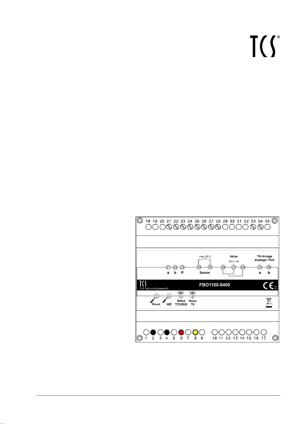
Device overview.................................................................................................................5
Indication and operating elements...................................................................................6
Intended use.......................................................................................................................6
Short description...............................................................................................................7
Connect the lines...............................................................................................................7
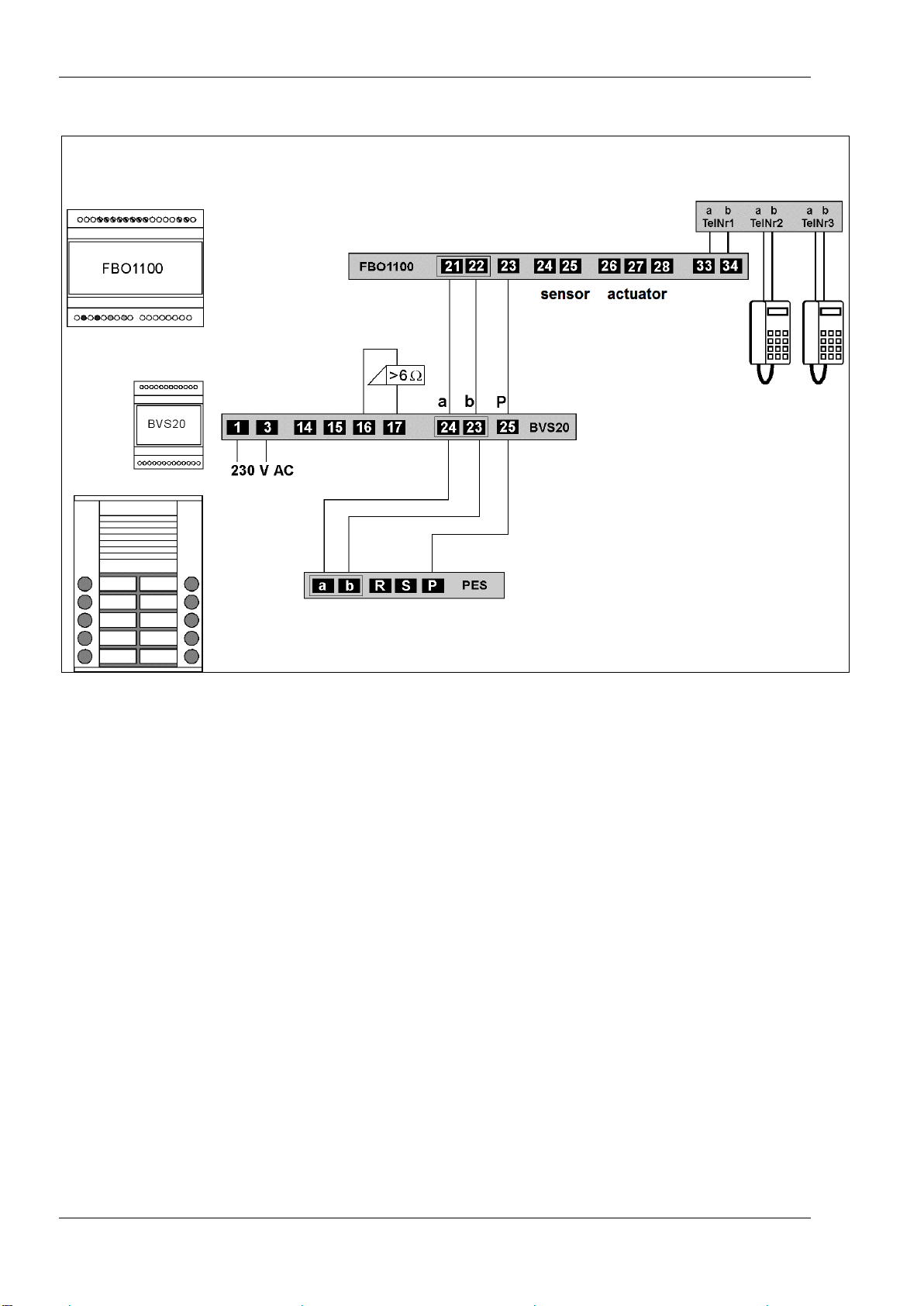
Connection diagram.........................................................................................................7
Wiring diagram: minimum installation...............................................................................8
Commissioning..................................................................................................................9
Functional principle..........................................................................................................9
Legends ...........................................................................................................................9
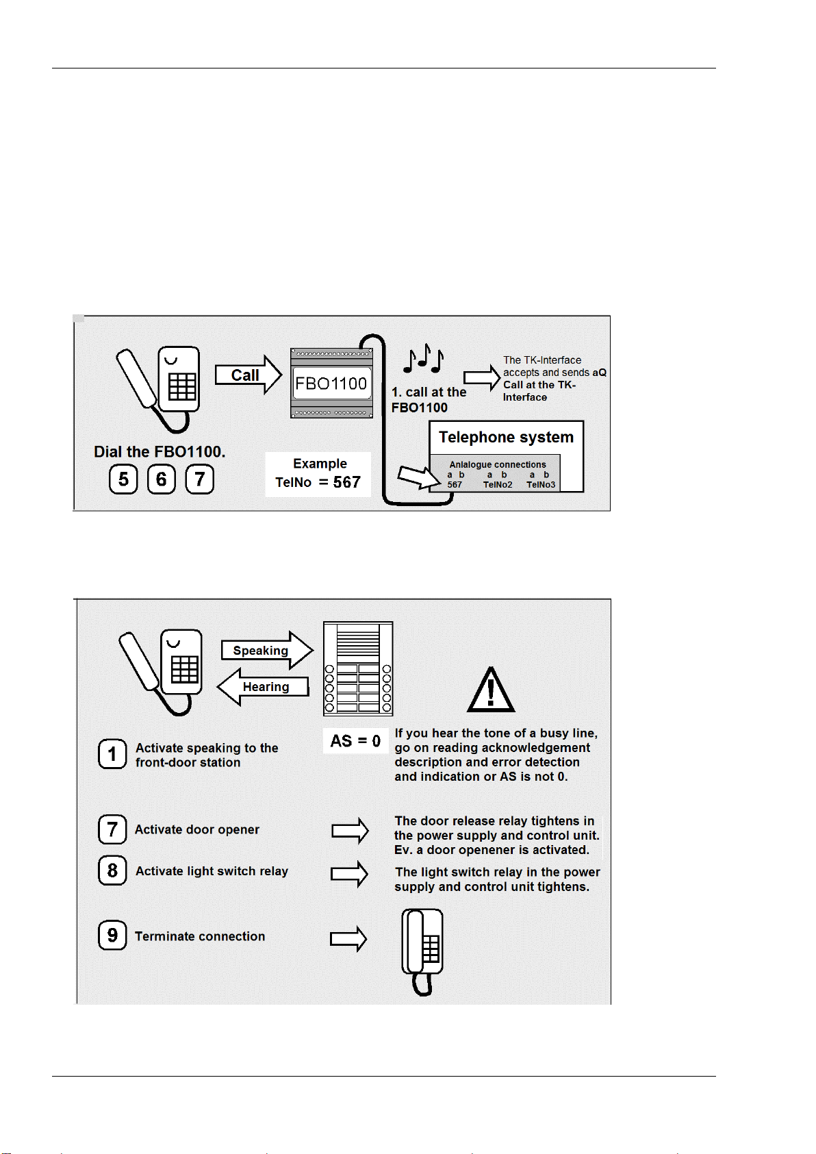
Acknowledgement and signal tones.............................................................................9
Keystroke......................................................................................................................9
Used abbreviations.......................................................................................................9
Commissioning steps.....................................................................................................10
Error detection and indication.........................................................................................11
Configuration...................................................................................................................12
Factory settings..............................................................................................................12
Configuration options .....................................................................................................12
Programming the FBO1100.............................................................................................13
Brief overview of all commands......................................................................................13
Causal link between serial numbers and dialing registers (per block number)...............15
… Variant with 4 dialing registers ...............................................................................15
… Variant with 16 dialing registers .............................................................................15
… Variant with 32 dialing registers .............................................................................15
… Variante mit 64 Wahlspeichern ..............................................................................16
Programmiermodus EIN / AUS ......................................................................................16
Set the block number (command 18).............................................................................17
Enter user telephone numbers and programming bell buttons.......................................17
… via TCSK-01...........................................................................................................18
… directly at the FBO1100 .........................................................................................18
Settings ............................................................................................................................19
Communication time ......................................................................................................19
Number of ring tones (signals).......................................................................................19
Actuator output switch time............................................................................................20
Call time.........................................................................................................................20
Change the PIN..............................................................................................................20
Reload to factory settings...............................................................................................21
Operating..........................................................................................................................21
Technical data..................................................................................................................22
Conformity........................................................................................................................22
Information on disposal..................................................................................................22
Warranty...........................................................................................................................22
Service..............................................................................................................................24

4 04/2013
TCS TürControlSysteme AG, TCS Hotline Germany: +49 (0) 41 94/ 9 88 11 88 Subject to technical changes.
FAX: +49 (0) 41 94/ 9 88 129 Mail: hotline@tcsag.de PI_FBO1100_uk 1A
Scope of delivery
1 x FBO1100-0400
product information
brief overview
Safety instructions
General safety regulations
!
Attention! Mounting, installation, commissioning and repair of electronic devices have
to be carried out only by qualified electricians. Thus, the current standards for the in-
stallation of door communication systems must be observed.
For working on systems with main connection of 230 V alternating voltage, the safety regu-
lations according to DIN VDE 0100 must be observed.
When installing TCS:BUS®systems, the general safety regulations for telecommunication
systems according to VDE 0800 must be observed. Inter alia:
separated conduit of heavy and low current lines,
minimum distance of 10 cm in case of a common conduit,
use of separators between heavy and low current lines within shared cable ducts,
use of standard communication lines, e.g. J-Y (St) Y with 0.8 mm diameter,
existing lines (modernisation) with deviating cross-sections can be used in compliance
with the loop resistance.
Installation –protective measures
!
With suitable measures to protect against lightning, it has to be ensured that a voltage
of each 32 V DC is not exceeded at the connections.

04/2013 5
TCS TürControlSysteme AG, TCS Hotline Germany: +49 (0) 41 94/ 9 88 11 88 Subject to technical changes.
FAX: +49 (0) 41 94/ 9 88 129 Mail: hotline@tcsag.de PI_FBO1100_uk 1A
Device overview
connection TCS:BUS
connection sensor
connection actuator
connection PBX / PSTN
Reset push button
push button
Load factory setting
indication status TCS:BUS
indication status PBX / PSTN connection

6 04/2013
TCS TürControlSysteme AG, TCS Hotline Germany: +49 (0) 41 94/ 9 88 11 88 Subject to technical changes.
FAX: +49 (0) 41 94/ 9 88 129 Mail: hotline@tcsag.de PI_FBO1100_uk 1A
Indication and operating elements
Term
Function
Reset push button
for reset, restart the software
to reload factory settings
button Reload factory
setting WE
to reload factory settings
Status indication
TCS:BUS
(red LED)
OFF: stand-by
ON: during a voice connection between TCS:BUS and PBS / PSTN
both LEDs ON: when reloading the factory setting
blinks slowly: busy (voice connection or alarming, announcement)
blinks fast: a-wire is not connected or supplied
flashes OFF: device is activated for programming with configuration software
configo™
flashes ON: door call, internal call or sensor signal received
flashes ON, once, long break: a-, P-wire are exchanged or short-circuited
flashes ON, twice, long break: error duplication of the block number and
different device versions
flashes ON, three times, long break: error duplication of the block number
in case of identic devices
Status indication
PBX / PSTN connec-
tion (yellow LED)
OFF: error P-wire is not connected or not supplied
ON, briefly: as long as a call signal comes in at the TK-Interface
ON: after a door call, during connection establishment and voice connection
both LEDs ON: when reloading to factory settings
blinks slowly: programming mode active
blinks fast: once, connection to the PBX / PSTN cannot be realised, occu-
pied
flashes OFF: after a door call with deviated connection establishment, until
the end of the delay time
flashes ON: connection to the sensor without speaking
flashes ON, once, long break: variant with 16 dialing registers
flashes ON, twice, long break: variant with 4 dialing registers
flashes ON, three times, long break: variant with 32 or 64 dialing registers
Intended use
The FBO1100 is an interface for the connection from the TCS:BUS to a telephone net in
order to establish a voice connection between a TCS:BUS client (front-door or indoor
stations) and a client within the telephone net.
The connection is realised via an analogue port.
Up to 64 FBO1100 can be connected to a TCS:BUS.

04/2013 7
TCS TürControlSysteme AG, TCS Hotline Germany: +49 (0) 41 94/ 9 88 11 88 Subject to technical changes.
FAX: +49 (0) 41 94/ 9 88 129 Mail: hotline@tcsag.de PI_FBO1100_uk 1A
Short description
connection via a standard PBX / PSTN analogue interface
sensor to trigger a connection establishment / separate dialing register
sensor requires the connection of a potential-free switch
dialing register with 4, 16, 32, or 64 call numbers with max. 16 digits, can be pro-
grammed/adjusted, delivery state: 16 dialing register
telephone buttons of standard telephones and cell phones switch door release, lights
and create control functions via multi-frequency dialing
specific connection to 56 front-door stations with a standard (cell phone) telephone
specific internal call from up to 3 indoor stations with a standard (cell phone) telephone
specific triggering of up to 10 actuators per dialing register with a standard (cell phone)
telephone
day / night mode
call diversion (from the indoor station to the TK-Interface)
actuator, potential-free relay contact (two-way contact: 24 V DC / 1 A)
switch time of the relay ex works: 10 seconds / adjustable via MFV (multi-frequency di-
aling)
up to 64 FBO1100 can be connected to one TCS:BUS
status indication for operation modes and transmission state
optical error indication
configuration via DTMF (multi-frequency dialing) or configuration software configo™
(as of version 1.6.0.6)
busy tone detection to terminate the conversation automatically, only hang-up the hand-
set
energy-saving when in stand-by mode (240 mW)
Connect the lines
The FBO1100 is connected to the PBX / PSTN just like an analogue telephone.
The FBO1100 needs a TCS:BUS, that at least consists of power supply and control unit
and a front-door station. Alternatively, also indoor stations can use the FBO1100 as in-
terface.
Connection diagram

8 04/2013
TCS TürControlSysteme AG, TCS Hotline Germany: +49 (0) 41 94/ 9 88 11 88 Subject to technical changes.
FAX: +49 (0) 41 94/ 9 88 129 Mail: hotline@tcsag.de PI_FBO1100_uk 1A
Wiring diagram: minimum installation
PBX / PSTN
analogue interface

04/2013 9
TCS TürControlSysteme AG, TCS Hotline Germany: +49 (0) 41 94/ 9 88 11 88 Subject to technical changes.
FAX: +49 (0) 41 94/ 9 88 129 Mail: hotline@tcsag.de PI_FBO1100_uk 1A
Commissioning
Functional principle
Legends
Acknowledgement and signal tones after a call
aQ programming mode ON
/ entry is stored
aQ: call at the TK-Interface
aQ: entering the Pin is required
aQ entry invalid
aQ: end of connection
Keystroke
Press button until …
Shortly press the button
Release the button
Used abbreviations
aQ acoustic acknowledgement
aH acoustic signal
1) example call number!
2) only when block number = 72
Type = 16 dialing register

10 04/2013
TCS TürControlSysteme AG, TCS Hotline Germany: +49 (0) 41 94/ 9 88 11 88 Subject to technical changes.
FAX: +49 (0) 41 94/ 9 88 129 Mail: hotline@tcsag.de PI_FBO1100_uk 1A
Commissioning steps
Install the devices at the TCS system completely and connect the FBO1100 to the tele-
phone system (see wiring example).
Check the a-, b- and P-wire against each other for short-circuits.
Switch on the mains voltage.
The yellow LED (state PBX / PSTN connection) flashes ON, once with a long break
(This corresponds with the TK-Interface (16 dialing register = delivery state).
(blink mode: also see Indication and operating elements, page 6, )
First check the connection of the FBO1100 to the telephone system with a call to the
telephone number which is assigned to the FBO1100 from the telephone system.
Then, check the connection of the FBO1100 to the front-door station by pressing the
Button 1 as well as the function of the Buttons 7 and 8. The connection can be end-
ed by pressing the Button 9 or by hanging up the handset.
Thus, the system is basically ready to operate and can be configured.
If the commissioning check is not successful, errors may have occurred.

04/2013 11
TCS TürControlSysteme AG, TCS Hotline Germany: +49 (0) 41 94/ 9 88 11 88 Subject to technical changes.
FAX: +49 (0) 41 94/ 9 88 129 Mail: hotline@tcsag.de PI_FBO1100_uk 1A
First, eliminate the following errors:
acknowledgement, description
acoustic
reaction
optical
reaction
“The called“ is busy: acknowledgement after calling a stored num-
ber, if the called client is busy (audible at the front-door station).
yellow LED
blinks fast
Unsuccessful call: acknowledgement after calling a stored number, if
the called client is not accepting within a period of time (audible at
the front-door station).
yellow LED
blinks fast
”Dialing register empty“: acknowledgement as reaction to pressing a
bell button, if no call number is entered in the dialing register (audi-
ble at the front-door station).
yellow LED
blinks fast
Then check the system for errors.
Error detection and indication
Errors are signaled optically and acoustically:
After the call at the FBO1100 an error tone sounds for three times (audible at the tele-
phone), then the connection is disconnected.
The red LED at the TK-Interface blinks or flashes permanently (see table below).
The optical error indication at the TK-Interface stays active until the error is corrected.
error causes
red LED
yellow
LED
error
tone
description, solution
TCS:BUS is busy
blinks
slowly
OFF
Acknowledgement after calling the
FBO1100, if a voice connection is acti-
vated at the TCS:BUS or an alerting or
announcement is running (audible at
the telephone)
After a timeout of 5 min the status
must be finished
a- and P-wire
interchanged or short-circuited
flashes
OFF
Every 2 min, the system is checked if
the error still exists.
exchange a- and P-wire or eliminate
short-circuit, device is in stand-by
mode again
BUS error a:
a-wire is not connected or not
supplied
blinks
fast
ON
connect the a-wire or check mains
connection, device is in stand-by
mode again
variant error*
TK-Interface has a different vari-
ant, as an already connected one
but the same block number
flashes
twice,
long
break
OFF
press the Reset button
change the block number of the
FBO1100 to another value
block number error*
TK-Interface has the same vari-
ant and the same block number,
as an already connected one
flashes
three
times,
long
break
OFF
press the Reset button
change the block number of the
FBO1100 to another value
* The SN20 bit-function is moved to an invalid area for the TK-Interface (SN 2044, BlNr 128).

12 04/2013
TCS TürControlSysteme AG, TCS Hotline Germany: +49 (0) 41 94/ 9 88 11 88 Subject to technical changes.
FAX: +49 (0) 41 94/ 9 88 129 Mail: hotline@tcsag.de PI_FBO1100_uk 1A
Configuration
Factory settings
Factory settings see FBO1100 short overview of all commands.
Configuration options
co
mm
and
function
manually
configoTM
as of version
1.6.0.6
10
enter a PIN
x
x
11
determine the dialing register number for the sensor
x
x
12
enter or delete a call number in the dialing register
x
x
13
check the content of the dialing register XX
x
–
14
assignment of a TK-Interface dialing register to a bell button
x
–*
15
set the minimum duration of a conversation
x
x
16
determine the number of the calls until the TK-Interface accepts
the call
x
x
17
set the activation time of the output port for
button
x
x
18
set the block number for the TK-Interface
x
x
19
service function listen-in
x
–
20
set the exchange type
x
x
21
enter the exchange code
x
x
22
train an internal client to the buttons 4 / 5 / 6,
delete the buttons 4 / 5 / 6
x
x
23
control remote maintenance
x
–
24
define the function of the sensor
x
x
25
define the type of the connection start. Not in case of a call diversion!
x
x
26
set the delay of the dialing start
x
x
27
enter the successor of the dialing register ID in case of call diver-
sion
x
x
28
add the night dialing register ID to the storage space in case of day
/ night mode
x
x
29
activation of the actuator port when a call comes in via
dialing register
x
x
30
duration of the call for this dialing register
x
x
31
control of the connection establishment
x
x
32
control of the acknowledgement tone during a call from a front-
door station
x
x
33
enter the AS-address to the sensor in case of a voice connection
x
x
34
starts the transmission of the internal parameter block of the TK-
Interface
x
x
35
starts the read-out of the parameter block to the dialing register
x
x
36
enter the project number with 4 digits
x
–
37
control of the error tone output
x
x
38
set the function of an internal call to the TK-Interface
x
x
39
activate the function input PIN
x
x
40
set the timeout after the dialing
x
x
41
set the door release commands
x
x
42
set the delay time
x
x
43
set the reaction on a call at the TK-Interface
x
x
44
blank dial tones / do not modify
x
x
45
acoustic note ”call at a TK-Interface”when incoming call on / off
x
x
46
number of the dialing register / set the type of the TK-Interface
x
x
47
activate / deactivate number mode
x
x
48
activate the training of the serial number to the number mode
x
x
* in connection with configuration of the front-door station

04/2013 13
TCS TürControlSysteme AG, TCS Hotline Germany: +49 (0) 41 94/ 9 88 11 88 Subject to technical changes.
FAX: +49 (0) 41 94/ 9 88 129 Mail: hotline@tcsag.de PI_FBO1100_uk 1A
Programming the FBO1100
Brief overview of all commands
Command Parameter
End of
com-
mand
Function
Factory setting
of the parame-
ter
PIN
10 X XXX
*
Enter a PIN
0000
Dialing register
11 X X
*
Determine dialing register number for the sensor
10…
Dialing register Tel. call number
12 X X Y…Y
*
Enter or delete (no YYYY) a call number in the dialing register XX
deleted
Dialing register
13 X X
*
Checks the content of the dialing register XX
none
Dialing register
14 X X
*
Assignment of a TK-Interface dialing register to a bell button
none
Communication time in s
15 X X
*
Setting the minimum duration of a conversation,
88 s = unlimited
(entry 11: 1 min, entry 12: 2 min, … entry 19: 9 min)
3 min (13)
Number of call signals
16 X
*
Determine the number of calls until the TK-Interface accepts the
call
2
Activation time in s
17 X X
*
Setting the activation time of the output port at
Button (10=10s / 11=1s / ...19=9s / 20s ... 90s)
10
Block number
18XX
*
Setting the block number for the TK-Interface
10/72/24/10
Control
19 X
*
Service function Eavesdropping
0 = can be activated with the button Reload factory setting
1 = activate always automatically
0
0=PSTN 1=PBX 2=Hotline
20 X
*
Setting the exchange type
0
Exchange code
21 X oder XX
*
Enter the exchange code,
(special case 01=FLASH / 02=MFV* / 03=MFV# / 04=FLASH + MFV* / 05=FLASH
+ MFV* + MFV* / 06=MFV* + MFV*)
0
Digit of the quick dial button
22 4 or 5or 6
*
Train an internal client on the buttons 4 / 5 / 6
Delete the buttons 4 / 5 / 6
none
0=OFF 1=ON
23 0 or 1
*
Control remote maintenance
0
0=Call 1=TOE 2=Day/Night
24 0 or 1or 2
*
Define the function of the sensor
0
0=Button 7 1=speak immed.
25 0 or 1
*
Define the type of the connection start
ATTENTION, not in case of a call diversion!
1
Dial delay in s
26 0 or 1or ... 9
*
Setting the delay of the dial start
(special case 0 = controlled by tone)
3
Dialing register Dial st. successor
27 X XYY
*
Enter the successor (YY) to the dialing register XX in case of a
call diversion
deleted
Dialing register dial st. (NIGHT)
28 X XYY
*
add the night dialing register ID to the storage space XX in case
of day / night mode
deleted
Dialing register activation time
29 X XYY
*
Activation of the actuator when calling via
dialing register XX, 0 = OFF
88 = door release automatic, TCS:BUS command
0
Dialing register call time
30 X XYY
*
Duration of the call for this dialing register
30
0=low priority. / 1=medium priority
/ 2=high priority
31 X
*
Controlling the establishment of the connection
2
0=OFF 1=ON
32 X
*
Controlling the switch-off tone while calling a front-door station
1

14 04/2013
TCS TürControlSysteme AG, TCS Hotline Germany: +49 (0) 41 94/ 9 88 11 88 Subject to technical changes.
FAX: +49 (0) 41 94/ 9 88 129 Mail: hotline@tcsag.de PI_FBO1100_uk 1A
command parameter
end of
com-
mand
function
factory setting
of the parame-
ter
Sensor AS address (10 ... 63)
33 X X
*
Enter the AS address to the sensor in case for a voice connec-
tion
64
no voice connection
34 no parameter!
Starts the transmission of the TK-Interface internal parameter
block
none
Dialing register
35 X X
*
Start of the read-out of the parameter block to the dialing regis-
ter XX
none
Project number (0000 ... 9999)
36 X XXX
*
Enter the project number with 4 digits
0000
0=OFF 1=ON
37 X
*
Control of the error tone output
1
0= ignore 1= door call 2= floor call
38 X
*
Setting the function of an internal call to the TK-Interface
2
0=no PIN 1=input PIN
2=HW-Reset
39 X
*
Activating the function of an input PIN
01)
0=short 1=long
40 X
*
Setting the timeout after the dial
short = 10 s / long = 45 s
1
0=16bit, short 1=32 bit, long
41 X
*
Setting the door release command
0
0=short 1…9 (* 30s = 30…270 s)
42 X
*
Setting the delay time
0
0=commands 1directly to AS(2)
43 X
*
Setting the reaction on the call at the TK-Interface
0
0=normal 1=blank
44 X
*
Blank / not change the dial tones
0
0=no acous. note 1=note
45 X
*
Acoustic note ”call at the TK-Interface“ at the incoming call
1
0=4 dialing reg. 1=16 dialing reg.
2=32 dialing reg. 3=64 dialing reg.
46 X
*
Number of dialing register / set the type of the TK-Interface
1
0=deactivate the numeric mode
1=activate the numeric mode
47 X
*
Activate / deactivate the numeric mode
0
0=no numeric mode SN
1=numeric mode, train the SN
48 X
*
Activate the training of the serial number (SN) to the numeric
mode
0
0=max. 20 Ohm 1=max. 60 Ohm
49 X
*
The max. permitted loop resistance between TK-Interface and
power supply and control unit
(1 not possible with BVS20)
0
1) If at command 46, parameter 0=4 dialing register is set, the factory setting automatically changes at command 39 to 1.
A long tone sounds when calling the TKI. Enter 0000 after the tone (see command 10).
aQ entry Pin expected when calling the TKI

04/2013 15
TCS TürControlSysteme AG, TCS Hotline Germany: +49 (0) 41 94/ 9 88 11 88 Subject to technical changes.
FAX: +49 (0) 41 94/ 9 88 129 Mail: hotline@tcsag.de PI_FBO1100_uk 1A
Link between serial numbers and dialing registers (per block number)
The following tables provide an overview over the link between serial number and dialing
register per block number. The list is arranged according to types (number of dialing regis-
ter) of the FBO1100-0400 and is limited to 10 block numbers per table. You can receive
more detailed tables on request. The white fields in the table state the serial number.
… Variant with 4 dialing registers
Block number
Dialing register 10 (min)
Dialing register 13 (max)
10
0
3
… Variant with 16 dialing registers
Block number
Dialing register 10 (min)
Dialing register 25 (max)
72
1008
1023
71
992
1007
70
976
991
69
960
975
68
944
959
67
928
943
66
912
927
65
896
911
64
880
895
63
864
879
… Variant with 32 dialing registers
Block number
Dialing register 10 (min)
Dialing register 41 (max)
40
992
1023
39
960
991
38
928
959
37
896
927
36
864
895
35
832
863
34
800
831
33
768
799
32
736
767
31
704
735

16 04/2013
TCS TürControlSysteme AG, TCS Hotline Germany: +49 (0) 41 94/ 9 88 11 88 Subject to technical changes.
FAX: +49 (0) 41 94/ 9 88 129 Mail: hotline@tcsag.de PI_FBO1100_uk 1A
… Variant with 64 dialing registers
Block number
Dialing register 10 (min)
Dialing register 73 (max)
24
960
1023
23
896
959
22
832
895
21
768
831
20
704
767
19
640
703
18
576
639
17
512
575
16
448
511
15
384
447
Programming mode ON / OFF

04/2013 17
TCS TürControlSysteme AG, TCS Hotline Germany: +49 (0) 41 94/ 9 88 11 88 Subject to technical changes.
FAX: +49 (0) 41 94/ 9 88 129 Mail: hotline@tcsag.de PI_FBO1100_uk 1A
Set the block number (command 18)
When more than one FBO1100 is connected to a TCS:BUS, first the block numbers of
the second and all further FBO1100 must be changed (delivery state of all FBO1100:
block number 72)
!
ATTENTION!
If the block number is changed after the assignment of the bell buttons, the
FBO1100 does not react when pressing these bell buttons. The bell buttons must
be deleted and programmed with the new serial number.
Enter user telephone numbers and programming bell buttons
To establish a voice connection from the door to a (mobile) telephone, a telephone
number must be entered in a dialing register and the entered telephone number must
be allocated to a bell button.
aQ entry is
stored

18 04/2013
TCS TürControlSysteme AG, TCS Hotline Germany: +49 (0) 41 94/ 9 88 11 88 Subject to technical changes.
FAX: +49 (0) 41 94/ 9 88 129 Mail: hotline@tcsag.de PI_FBO1100_uk 1A
… via TCSK-01
… directly at the FBO1100
max. 2 min

04/2013 19
TCS TürControlSysteme AG, TCS Hotline Germany: +49 (0) 41 94/ 9 88 11 88 Subject to technical changes.
FAX: +49 (0) 41 94/ 9 88 129 Mail: hotline@tcsag.de PI_FBO1100_uk 1A
Settings
Communication time
Number of ring tones (signals)
entry 11: 1 min
entry 12: 2 min
…
entry 19: 9 min

20 04/2013
TCS TürControlSysteme AG, TCS Hotline Germany: +49 (0) 41 94/ 9 88 11 88 Subject to technical changes.
FAX: +49 (0) 41 94/ 9 88 129 Mail: hotline@tcsag.de PI_FBO1100_uk 1A
Actuator output switch time
Call time
Change the PIN
Table of contents
Other TCS Recording Equipment manuals
Popular Recording Equipment manuals by other brands

SMA
SMA Webconnect Data Module installation manual

Fatar
Fatar STUDIO 90 instruction manual

Korg
Korg volca kick System firmware update instructions

Prolancer
Prolancer TotalRecallVR LinX Essence quick start guide

UTC AEROSPACE SYSTEMS
UTC AEROSPACE SYSTEMS Rosemount Aerospace 8730L Series user manual

LaMotte
LaMotte JT-1 manual

ALLEN & HEATH
ALLEN & HEATH WZ16:2 user guide

Miditech
Miditech midiface 4x4 Thru/Merge quick start guide

sonible
sonible missing link ml:1 BATTERY REPLACEMENT GUIDE

Mitsubishi Electric
Mitsubishi Electric RMF-CA100-V1 Installation instructions manual

PAC
PAC RP4.2-TY13 manual

Bastl Instruments
Bastl Instruments POPCORN v1.1 Assembly guide