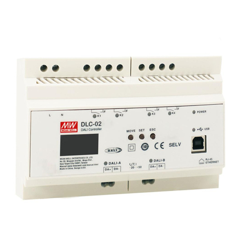
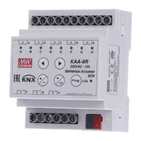
Meanwell KAA-8R Series User manual

KAA-8R
Universal Actuator
Instruction manual

Content
Version 0
1.Overview
2.Communication Objects
3.Reference ETS-Parameter – Switch for different application
1.1 Overview devices
2.1 Global communication objects
2.2 Default settings of the central communication objects
2.3 Default settings of the communication objects for each functions
3.1 General setting
3.2 Channel selection
3.3 Identical parameter
3.4 Switching output
3.5 Staircase
3.6 Switch impulse
3.7 Heating Control with PWM
1.2 Usage & possible applications
1.3 Exemplary Circuit diagrams
1.3.1 Switching actuator
1.5.1 Overview at general setting and functions
1.3.2 Mixed mode
3.3.1 Relay operating mode
3.3.2 Central function
3.3.3 Behavior at locking /unlocking
3.3.4 Behavior at bus power up/down
3.4.1 Overview
3.4.2 On/Off delay
3.4.3 Logic function
3.4.4 Scene function
3.4.5 Threshold switch
3.4.6 Operation hours counter function
3.5.1 Overview
3.5.2 Staircase time
3.5.3 Scenes (Staircase Light)
1.5.2 Overview functions at the switch/staircase mode/switch impulse/heating
1.4 Structure & Handling
1.5 Functions
1.6 Settings at the ETS-Software
1.7 Starting up
...............................................................................................................
.......................................................................................
...............................
..................................................................................................
................................................................................
.....................................................................................
.............................................................................................
..........................................................................
.................................................
..................................
.....................................................................................................
.................................................................................................
...............................................................................................
.........................................................................
......................................................................................................
...................................................................................................
..................................................................................................
...............................................................................................
...............................................................................................
............................................................................................
.....................................................................
.............................................................................................................
......................................................................................................
...............................................................................................
..................................................................................
.....................................................................................................
.......................................................................................
.................................................................................
....................................................................................
.........................................................................................
...........................................................
..................................................................................................
.................
.............................................................................................
............................................................................................................
...................................................................................
...........................................................................................................
1
5
6
1
5
5
5
6
7
8
8
9
9
10
11
11
13
14
16
18
19
20
20
23
24
24
27
1
1
1
3
2
3
2
3
4
4

KAA-8R Universal Actuator Instruction manual
1
1.Overview
1.1 Overview devices
The manual refers to the following devices: (Order Code respectively printed in bold type):
KAA-8R-10 Universal Actuator 8-fold, 230V AC, 10A.
◎4 Channels for shutter motors up to 600W, Manual control or 8 Channels for switching outputs for ohmic loads up to 2300W.
◎Any supposable mixed form of switching outputs and shutter output possible.
KAA-8R Universal Actuator 8-fold, 230V AC, 16A.
◎4 Channels for shutter motors up to 600W, Manual control or 8 Channels for switching outputs for ohmic loads up to 3680W.
◎Any supposable mixed form of switching outputs and shutter output possible.
1.2 Usage & possible applications
The universal actuator has its field of applications always if you ask flexibility. It can be parameterized as well as an adequate
switching actuator.
Further, there is the possibility of embedding the channel into automatic blocks and activate different scenes. At activation of the
automatic function, absolute position can be approached via 1 Bit object. This function is e.g. very suitable for the start-up of
sunblind positions, which are called via a brightness sensor. Additional weather alarms are parameterize able, which can call
determined functions at the universal actuator.
Additional a manual control of the shutter/blinds can be switched on or off.
Parameterized as switching actuator, the settings switching output and staircase are available. At the configuration switch, all
settings are available which are necessary for a comprehensive parameterization. As well On-/Off-delay, normally opened mode
or normally closed mode, cyclic sending, central function, logical functions as scene function are adjustable. Additional the reset
behavior and the blocking behavior can be set.
Via the staircase function an automatic switch off after a determined time can be adjusted.
1.3 Exemplary Circuit diagrams
1.3.1 Switching actuator
Parameterized as switching actuator, the actuator is connected in the following way:
Illustration 3: Exemplary circuit diagram as 8-fold switching actuator

2
1.3.2 Mixed mode
Also arbitrary mixed modes are possible, e.g. in the following way:
Illustration 4: Exemplary circuit diagram as switching and shutter actuator
Illustration 5: Overview hardware module (KAA-8R)
1.4 Structure & Handling
The universal actuator (KAA-8) contains of a programming button as well as a programming-LED, which shows a activated
programming button. The universal actuator works with 230V AC. Every channel of the MRDC device contains of a status-LEDs.
The status-LEDs show an active run-up or an active run-down command.
With the buttons left/right you can chose the channel and with the buttons up/down you can move the channel down or up.
The following illustration shows a 8-fold universal actuator:

3
The functionality is the same for all channels. Depending on the hardware module the device contains of up to eight channels.
At the first step, every channel can be selected as not active, Switch/Staircase/switch impulse, heating control with PWM
not active
The channel becomes no more functions allocated. There are no more opportunities to parameterize the channel.
Switch, Staircase, switch impulse, heating control with PWM
Every channel of the pair of channels can be selected individually as switch or staircase switch impulse…etc. at the next,
step.
If the channel is selected as switch, different switching actions can be parameterized. Additional actions, like logic functions
and scene functions, can be parameterized.
If the channel is selected as staircase, a staircase function, which causes an automatic cutout after an adjusted time, can be
parameterized. Additional settings for the adjustment of the staircase function are available. Like switch, staircase function,
you can find corresponding setting when selecting “switch impulse” or “heating control with PWM”. Please find detail
information in Later chapter.
1.5 Functions
1.5.1 Overview at general setting and functions
1.5.2 Overview functions at the switch/staircase mode/switch impulse/heating
Control with PWM
Parameter
Group of functions
Group addresses
Reset behavior
Switch functions
Forced control /priority functions
Time functions
Staircase light functions
Functions
number of objects/connections=dynamic
(freely assignable of the user)
behavior at bus power breakdown
switching
locking function
on-delay
time for staircase
manual off
Extend time on/off
behavior at bus power up
central switching function
logic functions (AND/ OR)
off-delay
pre-warning (with adjustable warning and
pre-warning time)
startup timeout
normally closed/ normally openedRelay mode
Channel selection
Startup Timeout
Manual Operation
Eco Mode,
switch LED's off after
send “operation” cyclic
(0=not active)
General settings
Descriptions
not active
switching
staircase light
switch impulse
heating control with PWM
After the device is powered on, the delay
of relay closed/separated.
Whether to allow manual operation of the
panel
Eco mode
Use to periodically report device status
Chart 1: Overview general setting and functions

4
Selection at the product database:
Manufacturer: MEANWELL Enterprises Co. Ltd
Product family: Output
Product type: Universal actuator
Product name: addicted to the used type, e.g.: KAA-8R universal actuator 8-fold, 16A
Order number: addicted to the used type, e.g.: KAA-8R
After wiring, the allocation of the physical address and the parameterization of every channel follow:
(1) Connect the interface with the bus, e.g. MEANWELL USB interface KSI-01U
(2) Switching the power supply
(3) Set bus power up
(4) Press the programming button at the device(red programming LED lights)
(5) Loading of the physical address out of the ETS-Software by using the interface(red LED goes out, as well this process was
completed successful)
(6) Loading of the application, with requested parameterization
(7) If the device is enabled you can test the requested functions(also possible by using the ETS-Software)
1.6 Settings at the ETS-Software
1.7 Starting up
Group of functions
Scenes
State functions
Switch impulse functions
Heating control with PWM
Functions
scene function for up to 8 scenes per channel
feedback function
Impulse time
PWM function
locking function
Emergency mode
Chart 2: Overview functions for switch, staircase mode

2.Communication Objects
2.1 Global communication objects
2.2 Default settings of the central communication objects
5
The central communication objects are standardly shown. They contain as well the communication objects, which are only valid
for corresponding functions.
The following chart shows the default settings of the global communication objects:
Default settings
Nr. Object Function Length Priority C R W T U
1 Manual Control 1 it Low XBX
2 Switch On/Off 1 it Low X XB
3 1 Bit Low X XXOperation
Chart 3: Default settings of the central communication objects
2.3 Default settings of the communication objects for each functions
The following chart shows the default settings of the communication objects, if the pair of channels is selected as shutter/blinds:
Default settings
Nr. Name Object Function Length Priority C R W T U
6 Channel A Switch Off 1 it Low XOn/ B X
7 Channel A Lock 1 t Low XBi X
8 Channel A State 1 it Low X XBX
9 Channel A Inverted tate 1 it LowSB
XX X
10 Channel A Forced ontrol 2 t Low XCBiX
10 Channel A Priority ON/ riority 1 it Low XPOFF B X
11 AChannel Scene\scene number 1 yte Low XBX
11 AChannel Scene\scene control 1 yte Low XBX
12 AChannel Logic1 1 Bit Low X X
13 AChannel Logic2 1 Bit Low X X
14 Channel A Threshold switch\ percentage 1 yte Low XBX
14 Channel A Threshold switch\ratio 1Byte Low XX
14 Channel A Threshold witch pulses 2 te Lows\ By XX
14 Channel A Threshold s\twitch emperatur 2 Byte Low
Low
Low
Low
Low
Low
XX
14 Channel A Threshold switch\lux 2 Byte XX
15 Channel A Service required
Time to next service\ time(h)
Time to next service\ time lag(s)
1Bit XX X
16 Channel A Response operating hours\ time lag(s) 4Byte XXX
16 Channel A Response operating hours \time(h) 2Byte X X X
16 Channel A 4 Byte X X X
You can see the default values for the communication objects from the upper chart. According to requirements the priority of the
particular communication objects as well as the flags can be adjusted by the user. The flags allocates the function of the objects in the
programming thereby stands C for communication, R for Read, W for write, T for transmit and U for update.
16 Channel A 2 Byte Low X X X
17 Channel A Reset Operation hours 1 it Low XBX
17 Channel A Reset ervice 1 t Low XSBiX

6
Default settings
Nr. Name Object Function Length Priority C R W T U
18 Channel A Staircase ight 1 it Low XlBX
19 Channel A Staircase ight th time 1 yte Low Xlwi B X
20 Channel A Prewarning 1 it Low XBX
21 Channel A Switch impulse 1 itBLow XX
22 Channel A State Emergency 1 it Low X XMode B X
23 Channel A Control alue 1 yte Low XVBX
+18 next pair of channels
Chart 4: Defaultsettingsofthecommunicationobjectsforeachfunctions
3.Reference ETS-Parameter – Switch for different application
3.1 General setting
The following illustration shows the menu of General setting.
Parameter Value Description
Startup Timeout 2 ~ 60s
After the device is powered on, the delay of relay closed/separated.
The manual operation allows the relay to be normally controlled during the delay
wait. If there is Object Communication, it will be recorded first and will not re-
spond. The delay ends and the corresponding action is executed.
Manual Operation
active
disable
lockable over object
Whether to allow manual operation of the panel.
Lockable over object: means to enable or disable the Manual Operation via
Object.
Eco Mode,
switch LED' off after
s
not active
30S 1min 2min 5min
10min 20min 30min
40min 50min 60min
Power saving mode. After the set time delay, turn off the LED on the panel.
send " peration" cyclicO
(0=not active) 0 ~ 30000min Use to periodically report device status. It is independent Operation Object

7
3.2 Channel selection
To operate the universal actuator as switching actuator, at first the each channel, e.g. Channel A, must be selected
as “switching”, “staircase light”,” Switch impulse”...etc. At the next step, for each channel can be selected if the
channel shall operate as switch for different application.
The following illustration shows the submenu channel selection:
Illustration 6: Channel selection
The following chart shows the available settings for the channel selection:
ETS-text
Dynamic range
[default value]
comment
Channel A not active
switching
staircase light
switch impulse
heating control with PWM
Selection, if a pair of channels shall operate as switching
actuator or as shutter actuator.
Not active deactivates the pair of channels.
Channel A switching
staircase light
switch impulse
heating control with PWM
At the switching/staircase light/switch impulse
mode/heating control with PWM. Theses settings are
available.
Channel H
Chart 6: Available settings channel selection for switch/staircase
Each channel can operate as switch.
At the chapter 4, the switching actuator mode is descripted. Each channel can be parameterized as well as switching output or
as its described function

8
3.3 Identical parameter
The following parameters is available at channels selected as switch as at channels selected as switch.
The following diagram shows the behavior of the relay operating mode normally closed and normally opened. The input for
the channels is a KNX-telegram, which sends alternating 0-signals and 1-signals:
3.3.1 Relay operating mode
The following illustration shows the setting options for this parameter:
I
illustration 7: Operating mode
The following chart shows the dynamic range for this parameter:
ETS-text
Dynamic range
[default value]
comment
Mode
normally opened
normally closed
Relay channeloperating mode of the
On delay 0-3000s
When the channel output is in the Off state, the message information of ON is re-
ceived, and it takes a delay itch On.of n seconds to sw
If the received message is also to switch on the output during the waiting period, it
will be ignored.
Note: The " n Delay erlapped with the " tartup Timeout" time inOS" time here is not ov
the " eneral Setting" above.G
Off delay 0-3000s
When the channel output is in the On state, the message information of Off is re-
ceived, and it takes a delay itch to the Off output.of n seconds to sw
Note: " time here is not overThe " ff Delay lapped with the " tartup Timeout" timeOS
in the " eneral Setting" above.G
Chart 7: Operating mode
KNX telegram
101 100
State
State
ON
ON
Mode: “ normally opened”
Mode: “ normally closed”
OFF
OFF
t
t
t

9
The following illustration shows the setting options at the ETS-Software:
Illustration 8: Central function
The following chart shows the dynamic range for this parameter:
ETS-text
Dynamic range
[default value]
comment
Central function not active
active
switches the central function
on/off for this channel
Chart 8: Central function
The following chart shows the associated communication object:
Number Name
Length Usage
2
Central function 1 Bit central switching of the channels
Chart 9: Communication object central function
3.3.2 Central function
3.3.3 Behavior at locking /unlocking
The central function can be switched on/off for every channel. For switching on this function, you have to choose the option
“active”. By calling the central communication object, all channels with an activated central function are switched on with
their current parameterization. So switch-on delays or staircase functions are still kept.
The locking function gets active, when the corresponding communication object becomes a logical 1 . By sending a
""
logical 0 , the locking function can be deactivated again.""
The parameter Behavior at locking defines an action for the output at activating the locking process.""
There are the setting on, off and no change available.
When the output channel is at the locking state, the manual button operation is invalid.
Note: Locking has the highest priority
The unlocking function gets active, when the corresponding communication object becomes a logical 0 . By sending a
""
logical 1 , the unlocking function can be deactivated again.""
The parameter Behavior at unlocking defines an action for the output at activating the unlocking. There are the setting""
on, off ,no change available, previous state, catch up on Switching and previous state.
Regarding the parameter previous state, catch up on Switching , If the actuator receives a message of type "Switch"
""
during locking, it will record it. After unlocking, the corresponding action will be executed on the output channel according
The following illustration shows the setting options at the ETS-Software:
Illustration 9: locking function
The following chart shows the dynamic range for this parameter:
ETS-text
Dynamic range
[default value]
comment
Behavior at locking On
Off
no change
Behavior to a locking/unblocking process
Behavior at unlocking
On
Off
no change
previous state, catch up on
Switching
previous state
Behavior to unlocking process
Chart 10: Behavior at locking/unlocking

10
The following chart shows the corresponding communication object:
Number Name
Length Usage
7
lock 1 Bit locks the channel
Chart 11: Communication object locking function
The following diagram describes the blocking process. For the “Behavior at locking”, the action on was parameterized and
for the “Behavior at unlocking” the action off was parameterized:
The KNX telegram shows which values are send to the locking object. By sending a logical “1”, the locking function is
activated and the channel is switched on. The locking function is deactivated again by sending a logical “0”. so the channel
is switched off.
Every channel can occupy a certain state as well in case of a bus power breakdown as in case of a bus power return. The
channel can be switched off or on, but also stay in its current state by choosing the parameter “no change”.
To avoid problems in case of a bus power breakdown, you should adjust this parameter very conscientious. Because there
is no controlling possible as long as the bus power is down.
KNX telegram
101 01
State
ON
OFF
t
t
Illustration 10: Behavior at bus power up/down
The following chart shows the dynamic range for this parameter:
ETS-text
Dynamic range
[default value]
comment
Behavior at bus power up/Behavior
at bus power down
On
Off
no change
Adjustment, how the channel shall react
in case of a bus power breakdown/return
Chart 12: Behavior at bus power up/down
3.3.4 Behavior at bus power up/down
The following illustration shows the setting options at the ETS-Software:

11
Illustration 28: Switching output
3.4 Switching output
The following parameters, which are described at the headings 5.3.x, are only available at channels selected as switch.
By choosing a channel as switch, a sub menu, called Channel A Switching, appears for this channel at the left drop down
menu.
3.4.1 Overview

12
The chart shows the possible settings for switching outputs:
ETS-text
Dynamic range
[default value]
comment
Mode normally opened
normally closed
Operation mode of the channel
On-Delay
0.... 0000 sec3
[]0=nodelay
Switch on delay of the channel in seconds
Off-Delay
0.... 0000 sec3
[]]0=no delay
Switch off delay of the channel in seconds
Central function not active
active
Activates the central function for this channel
Send state no send
at change
at change and lock
always at input of telegram
Set whether to send the telegram of "Status"
No send: do not send
At change: sent when the current output status changes
At change and lock: sent when the current state changes or during
the lock state
Note1: When the channel is locked, if the locking/unlocking behavior
is set to no change, the locking/unlocking will not send the " tate"
S
because the status will not change; but if the switch telegram is sent
during the locking period, Upload the current actual "State" (although
the output status has not changed)
Note2: During the channel locking =>unlocking
if there is no change on output state , "State" is not uploaded; if there
is a state change, "State" needs to be uploaded.
Note3: During the channel unlocking=>locking, if
if there is no change on output state, "State" is not uploaded; if there
is a state change, "State" needs to be uploaded.
Always at input of telegram: As long as the message of the
"Switch" type is received, it will be sent regardless of the output sta-
tus, even if it is in the locking state.
Send state cyclic
(0=not active)
0~30000s Set whether to send "State" telegram periodically.
Additional inverted state
not active
active
If the Additional inverted state is activated, the "Inverted State" mes-
sage is sent.
This activation will add an "Inverted State" Object that coexists with
the "State" Object.
Not active, "Inverted State" Object does not appear.
Behavior at locking Off
On
no change
Action for activating the locking process.
Note: Locking has the highest priority

13
ETS-text
Dynamic range
[default value]
comment
Behavior at unlocking Off
Off
On
On
no change
no change
previous state, catch up on
previous state, catch up on
switching
switching
previous state
previous state
Action for deactivating the unlocking process
Priority/Forced control not active
2 Bit force control
1 Bit Priority on
1 Bit Priority off
Priority control
Not active: not active
2 bit force control: 00/01 No Control, "10"-priority, Off; "11"-
priority, On
1 bit Priority On: "1" - enabled; "0" - released
1 bit Priority Off: "1" - enabled; "0" - released
Release time
for forced control
(0=not active)
:
0-600min
0: indicates that the forced control is always valid unless an
Object message is received to release the command;
1-600min: Forced control maintains the setting range of time.
When time is up, the forced control is automatically released.
Behavior after forced control:
Previous state, catch up on Switching: If the actuator re-
ceives "Switch" type telegram during the forced control, it will
record it. After forced control remove, the corresponding action
will be performed on the output channel according to the
latest set of "Switch" type telegram values received previous .ly
Previous state:After the forced control ends, the relay output
channel will restore the state value before the forced control.
Behavior after bus power
up
no change
off
on
Action for a bus power return.
If the actuator receives "Switch" type telegram during waiting the
power up. After the bus power up, the value of the Switch type tele-
gram is used and the bus power up setting is ignored.
Behavior after bus power
down
no change
off
on
Action for a bus power breakdown
Logic function not active
active
Whether the logic function is enabled or not
Scenes
not active
active
Whether the scene function is enabled or not
Threshold switch
not active
active
Whether the threshold control function is enabled or not
Operation hours
counter
not active
active
Whether the operation time statistics function is enabled or not
Chart 38: Switching output
The following illustration shows the setting options at the ETS-Software:
3.4.2 On/Off delay

14
KNX telegram
1010
State
ON
t on t ont off t off
OFF
t
t
The on-delay causes a delayed switch of the channel. At sending an on-signal to the channel, first the adjusted on delay time
expires and afterwards the channel will be switched on.
The off delay works on the same principle. At sending an off-signal, first the adjusted off delay time expires and afterwards the
channel will be switched off.
Both functions work as well alone as combined. By adjusting “0 seconds” for a delay the function is switched off.
The following diagram describes the combination of on and off delay:
The logic function can be activated with one or two objects. The objects are the inputs of the logic block. Furthermore you can
choose between an AND-function and an OR-function.
When you have activated the logic function, the logic block has to be satisfied before switching the channel. As long as the
logic function is not satisfied, the channel does not react to any signal.
The following illustration shows the setting options at the ETS-Software:
Illustration 30: Logic function
3.4.3 Logic function

15
The chart shows the possible settings for Logic function:
ETS-text Dynamic range
[default value]
Comment
Logic tionfunc
with Switch object and one Logic
object
with Switch object and two Logic
objects
With Switch object and one Logic object:
The calculated result of the switch object and logic1 object
as the executing value of the output channel.
With Switch object and two Logic object:
The calculated result of the switch object and logic1,logic2 object as the execut-
ing value of the output channel.
Note: The Switch object mentioned here is not limited to the "Switch On/Off"
Object. It is also included for the Switch brought by Object such as "Scene" and
"Threshold switch".
Logic ionsoperat
OR
AND
XOR
gate opened with Logic object=0
gate opened with Logic object=1
OR:At least one input is active (=1)
AND:All inputs are active (=1)
XOR:Only one input is active (=1)
gate opened with Logic object=0:The output can be switched via the switch-
ing object if all logic objects have the value 0
gate opened with Logic object=1:The output can be switched via the switch-
ing object if all logic objects have the value 1
Invert inputs
(with Switch object
and one Logic
object)
no invert
invert object Switching
invert Logic 1object
invert object Switching & Logic ject1ob
Whether to invert the input of the objects such as switch, logic1, etc.
(in the case of one logic Object)
Note: Invert object Switching is not only itch On/Off" Object.limited to the "Sw
It also works on " witch" brought by jects such as "Scene" and "ThresholdSOb
switch".
Invert inputs:
(with Switch object
and two Logic
object)
no invert
invert object Switching
invert Logic object1
invert Logic object2
invert object Switching & Logic object1
invert object Switching & Logic object2
invert Logic object1 & Logic object2
invert object Switching &Logic object1
& Logic object2
Whether to invert the input of the objects such as switch, logic1, logic2, etc.
(in the case of two Logic Objects)
Invert output
no invert
invert
Whether to invert the calculated results of the output
Set objects value
after bus power up
not active
active
It is used to set the initial values of three objects: switch, Logic1, and logic2
after the actuator is powered on.
If the setting is not activated, the default value of the three objects is "0",
and the Logic operation is not executed after power-on.
If the setting is activated, a Logic
operation is executed and output after
power-on.

16
The following chart shows the relevant communication objects:
Number Name
Length Usage
12 Logic 1 1 Bit Logic object 1, is the rst input for the logic
block
13 Logic 2 1 Bit Logic object 2, is the second input for the logic
block
Chart 39: Communication objects logic
According to the chosen logic operation only one or both objects have to become a 1-signal. The following chart shows the
both logic operations with two objects:
AND-Connection
OR-Connection
Logic 1 Logic 2 Channel
switchable?
Logic 1 Logic 2 Channel
switchable?
00
No
00
No
01
No
01 Yes
10
No
10 Yes
11 Yes 11 Yes
Chart 40: Logic operations
When functions of different groups (e.g. light, heating ) shall be changed simultaneously with only one keystroke, it is practical
to use the scene function. By calling a scene, you can switch the lights to a specific value, drive the shutter to an absolute
position, switch the heating to the day mode and switch the power supply of the sockets on. The telegrams of these functions
can have as well different formats as different values with different meaning (e.g. “0” for switch the lights off and open the
shutters). If there were no scene function, you would have to send a single telegram for every actuator to get the same
function.
The scene function of the switch actuator enables you to connect the channels of the switch actuator to a scene control. For
that, you have to assign the value to the appropriated space (scene A..H). It is possible to program up to 8 scenes per switching
output. When you activate the scene function at the switching output, a new sub menu for the scenes appears at the left drop
down menu. There are settings to activate single scenes, set values and scene numbers and switch the memory function on/off
at this sub menu.
Scenes are activated by receiving their scene numbers at the communication object for the scenes. If the memory function of
the scenes is activated, the current value of the channel will be saved at the called scene number.
The communication objects of the scenes have always the length of 1 byte.
For calling a certain scene, you have to send the value for the scene to the communication object. The value of the scene
number is always one number less than the adjusted scene number. For calling scene 1, you have to send a “0”. “o the scene
numbers have the numbers from 1 to 64, but the values for the scenes only from 0 to 63.
If you want to call scenes by a binary input or another KNX device, you have to set the same number at the calling device as at
the receiving device. The calling device, e.g. a binary input, sends automatically the right value for calling the scene.
There are up to 8 storage options for scenes at every channel.
3.4.4 Scene function
The following illustration shows the setting options at the ETS-Software for activating the scene function:
Illustration 31: Scene function
The following chart shows the relevant communication object:
Number Name
Length Usage
11
Scene
1 Byte Call of the scene
Chart 41: Communication object scene

17
These 8 storage options can get any of the possible 64 scene numbers.
Illustration 32: Sub function scene
The chart shows the possible settings for scenes, which are identical for all channels. The settings are available at the sub
menu for the scenes:
ETS-text Dynamic range
[default value]
Comment
Learn scene
not active
active
not active :The Learn scene function is not enabled
Object Value corresponds to DPT17.001 scene number.
active :Enable the Learn scene feature. Object Value corresponds to DPT
18.001 scene control.
Scene A
-----
not active
active
Whether to enable the setting of scene A
Scene number : 1-64
Behavior of scene :
off / on / lock / unlock
Note about the behavior of scene:
Behavior of scene = unlock,When the corresponding Scene number is re-
ceived, the channel is at lock state (locked by the lock object), then the Scene
Object can release the lock state of the channel.

18
Scene H
not active
active
Whether to enable the setting of scene H.
Supports up to 8 scene settings at every channel.
Scene number : 1-64
Behavior of scene :
off / on / lock / unlock
ETS-text Dynamic range
[default value]
Comment
The following illustration shows the setting options at the ETS-Software:
The chart shows all possible settings peration hours counter function:o
ETS-text Dynamic range
[default value]
Comment
Value setting
1 Byte percent value(0-100%)
1 Byte value(0-255)
2 Byte value(0-65500)
2 Byte temperature value(-100-250℃)
2 Byte brightness value(0-100000Lux)
Threshold setting, 5 types of threshold
Behavior of Channel at
lower deviation
not active
off
on
Behavior of Channel at lower threshold
Lower threshold< :
0-100%
0-255
0-65500
-100~250℃
0-100000 Lux
Threshold setting: five threshold ranges correspond to the
above five threshold types
Threshold comparison: compare to the value sent by the
"Threshold switch" Object.
If the value sent by the "Threshold switch" Object is less than
the threshold, the action set by "Behavior of Channel at lower
deviation" is executed.
Behavior of Channel at
exceedance
not active
off
on
Behavior of Channel at higher threshold
3.4.5 Threshold switch
Other manuals for KAA-8R Series
1
This manual suits for next models
2
Table of contents
Other Meanwell Controllers manuals
Popular Controllers manuals by other brands
Eaton
Eaton EMS-SWD Series manual

SEW-Eurodrive
SEW-Eurodrive MOVIPRO X4101 Addendum to the operating instructions
Friendess
Friendess WKB V6 user manual
YASKAWA
YASKAWA MOTOMAN FS100 instructions
Rodix
Rodix FEEDER CUBE CE-40 Plus Series Spare parts
Bard
Bard MC4002 Installation instructions & replacement parts list

