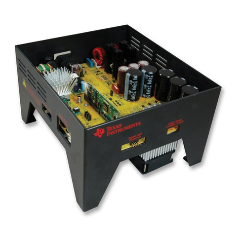
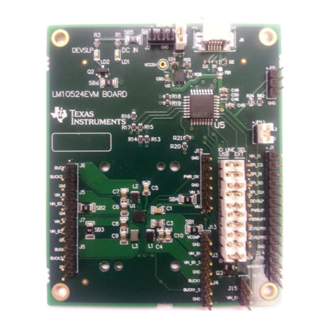
Texas Instruments TMS320C2000 User manual
Other Texas Instruments Controllers manuals
Texas Instruments
Texas Instruments TUSB422 EVM User manual

Texas Instruments
Texas Instruments DLP LightCrafter Dual DLPC900 Instruction sheet
Texas Instruments
Texas Instruments LM3429 User manual
Texas Instruments
Texas Instruments DLPC3430 Manual
Texas Instruments
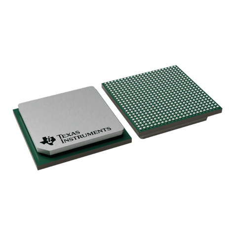
Texas Instruments DM648 DSP User manual
Texas Instruments
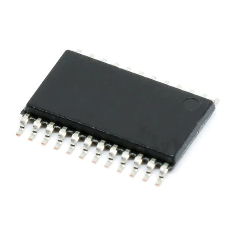
Texas Instruments TPS70351EVM User manual
Texas Instruments
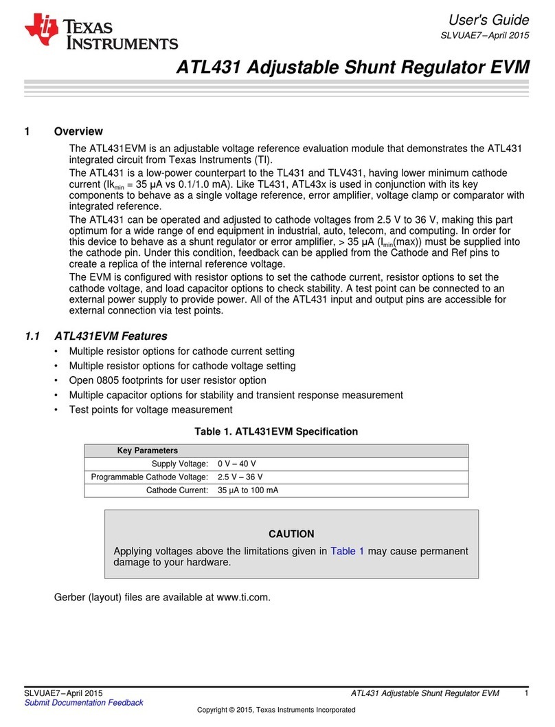
Texas Instruments ATL431 User manual

Texas Instruments
Texas Instruments Stellaris MDL-BDC24 User manual
Texas Instruments
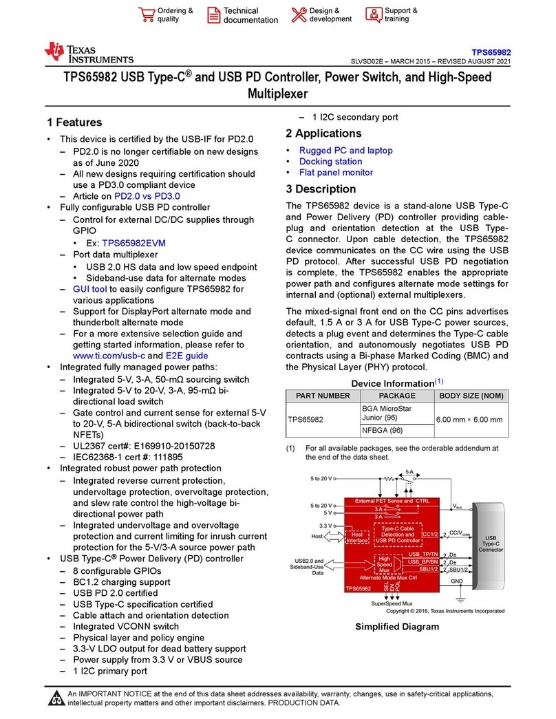
Texas Instruments TPS65982 User manual
Texas Instruments
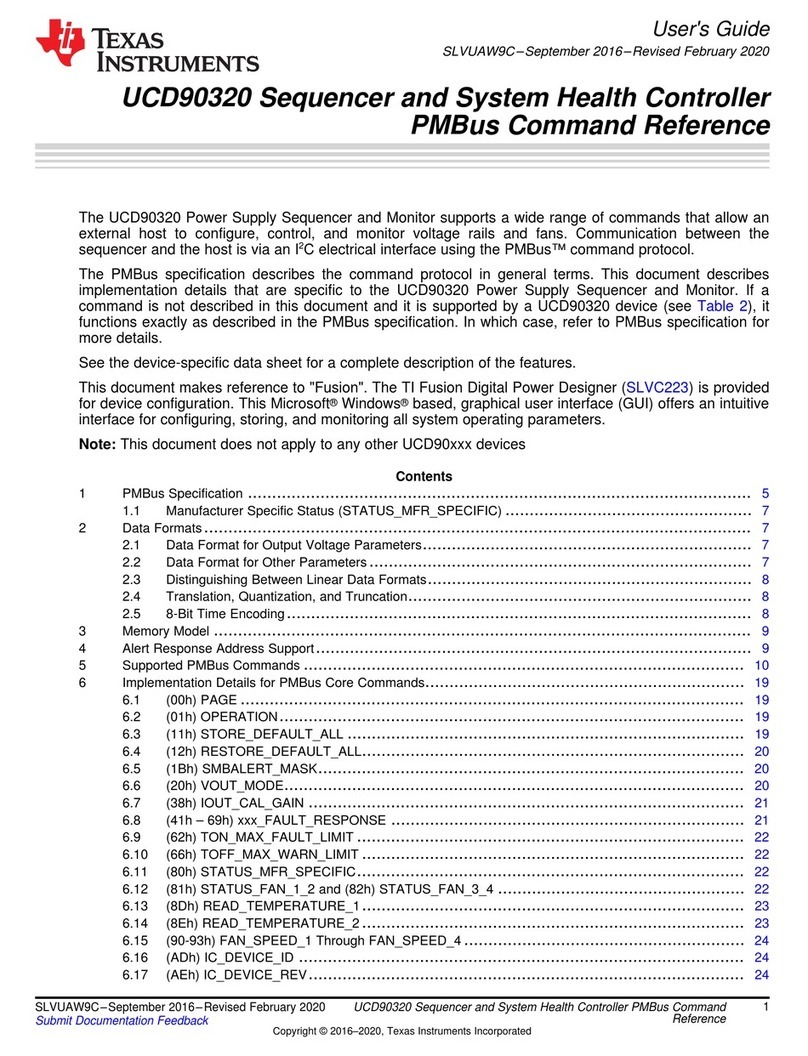
Texas Instruments UCD90320 User manual
Texas Instruments
Texas Instruments OMAP5910 User manual
Texas Instruments
Texas Instruments TMS320C6747 DSP User manual
Texas Instruments
Texas Instruments TCAN4550-Q1 User manual
Texas Instruments
Texas Instruments TSB12LV26 Installation and user guide
Texas Instruments
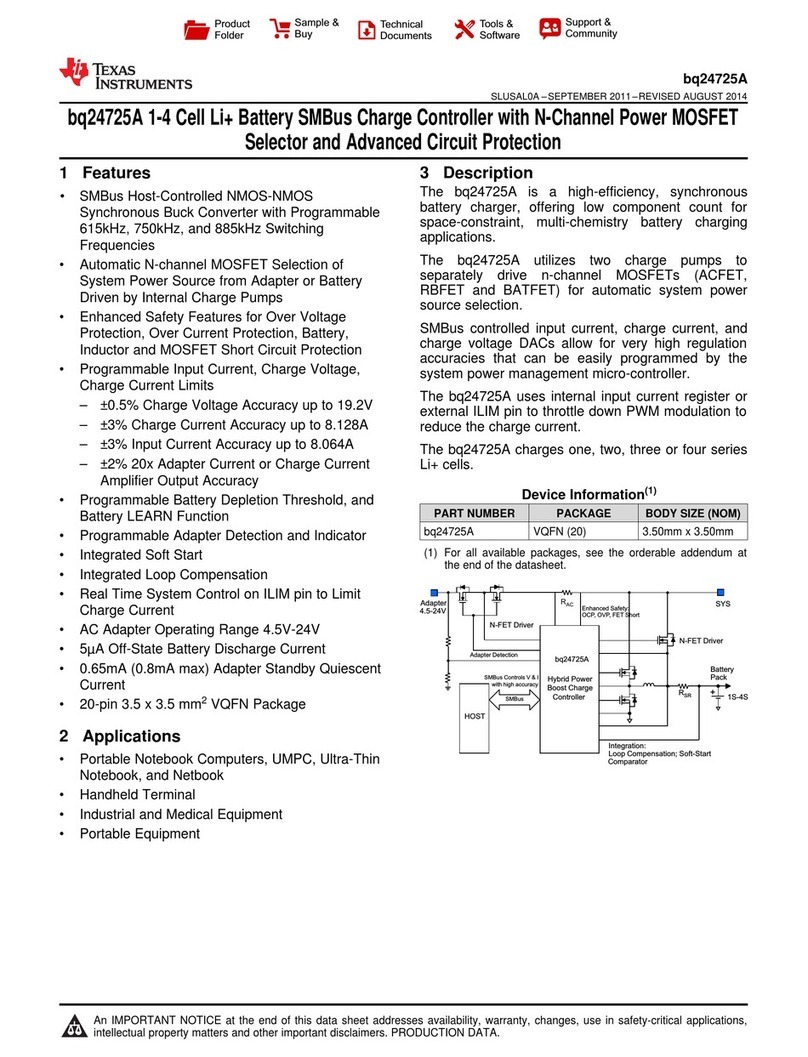
Texas Instruments bq24725A User manual
Texas Instruments
Texas Instruments TMS320 2833 Series User manual
Texas Instruments
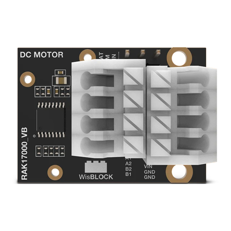
Texas Instruments DRV8833 User manual
Texas Instruments
Texas Instruments MSMC User manual
Texas Instruments
Texas Instruments TMS320C6000 DSP User manual
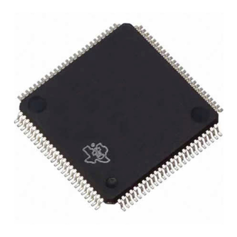
Texas Instruments
Texas Instruments TUSB2136 User manual
Popular Controllers manuals by other brands

Digiplex
Digiplex DGP-848 Programming guide

YASKAWA
YASKAWA SGM series user manual

Sinope
Sinope Calypso RM3500ZB installation guide

Isimet
Isimet DLA Series Style 2 Installation, Operations, Start-up and Maintenance Instructions

LSIS
LSIS sv-ip5a user manual

Airflow
Airflow Uno hab Installation and operating instructions
