M E A S U R E M E N T S Y S T E M S I N T E R N A T I O N A L
Page 2
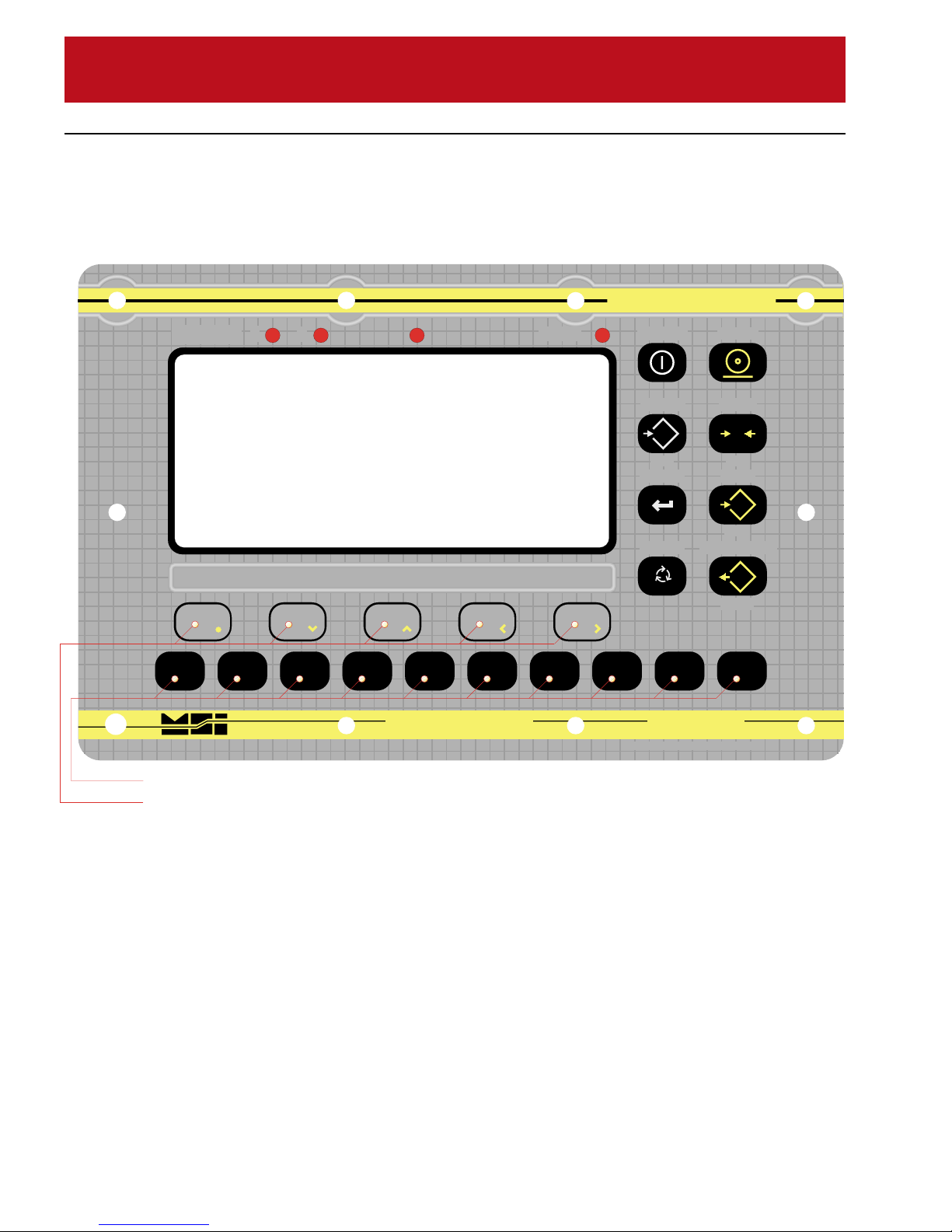
MSI-3750 Digital Weight Indicator
◆
User Guide
TABLE OF CONTENTS
INTRODUCTION....................................................3
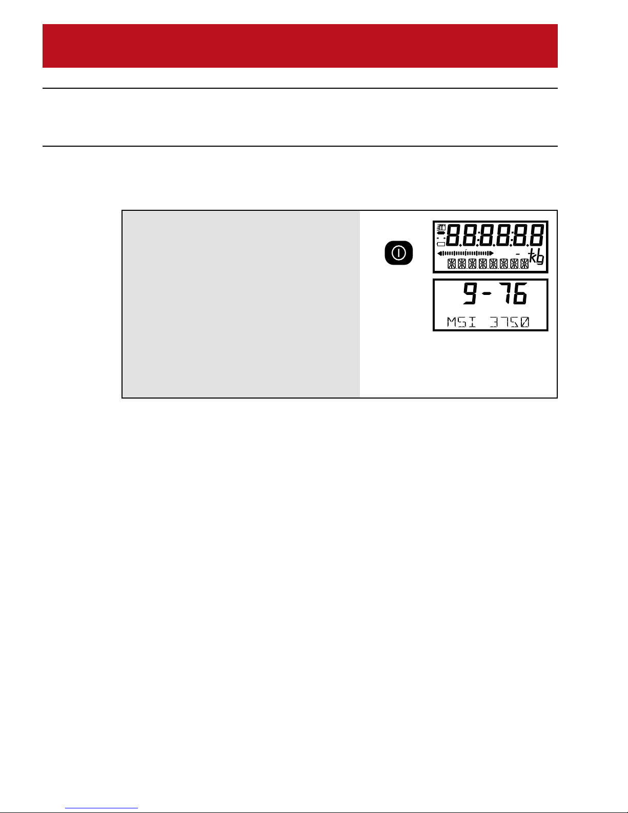
3750 Display.......................................................3
3750 Front Panel ................................................ 4
Features .............................................................5
Batteries (Option) ...............................................6
Load Cell Hookup ............................................... 7
SECTION 1 – SCALE OPERATION ...................... 8
Power .................................................................8
Zero ....................................................................9
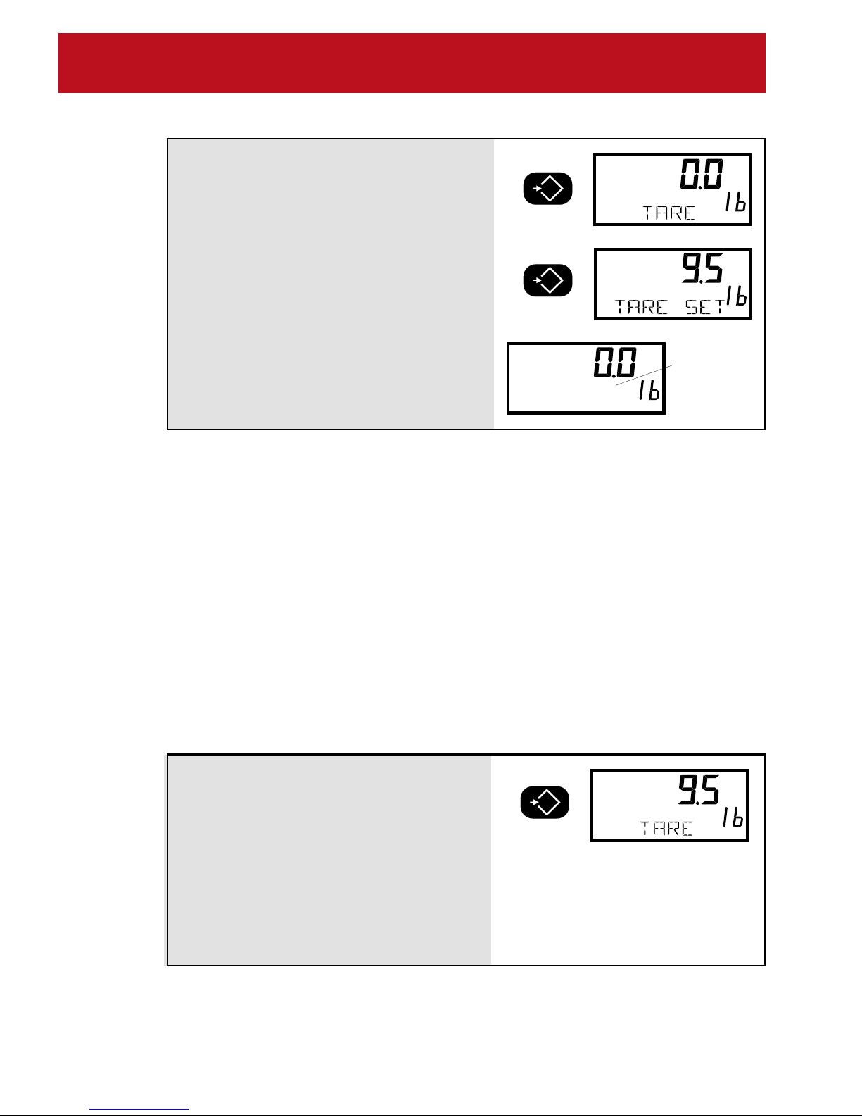
Tare..................................................................... 9
Setup Tare ........................................................ 13
Net/Gross .........................................................16
Units .................................................................16
Setup Units ....................................................... 17
Peak Hold (Function Key Option) ..................... 18
Print .................................................................. 19
Test ................................................................... 19
SECTION 2 – FUNCTION KEYS ......................... 20
Setup Function Keys ........................................20
SECTION 3 – ID CODES..................................... 22
ID Code Organization ....................................... 22
Using ID Codes ................................................24
Setup ID Codes ................................................ 30
ID Code String 1 & String 2 .............................. 33
SECTION 4 – TOTAL / STATISTICS....................35
Total .................................................................. 35
Auto Total..........................................................36
Total Menu (Setup Total)................................... 37
View Total .........................................................40
Clear All Totals.................................................. 42
Statistics (Option) ............................................. 42
Definitions And Formulas.................................. 43
Using Statistics ................................................. 44
SECTION 5 – 3750 METER SETUP.................... 46
Main Setup Menu .............................................46
Filter.................................................................. 47
LCD Contrast.................................................... 48
Real Time Clock/Calendar................................ 49
Setup Power Menu ........................................... 50
LCD Backlight................................................... 51
Bargraph Menu................................................. 52
Lock .................................................................. 54
SECTION 6 – SET POINTS................................. 58
Setup Set Points Menu..................................... 58
Set Point 1 Through Set Point 8 ....................... 60
Using Set Points ............................................... 62
Enabling / Disabling Set Points ........................66
Using The MSI 3750 As A Grading Scale ......... 67
Relay Output Option ......................................... 69
Relay Applications ............................................ 70
Logic Output (Set Point 8) ................................72
Test Set Point Relays ....................................... 73
SECTION 7 – COMMUNICATION PORTS.......... 74
Electrical Conformance .................................... 74
Comm Port Cabling .......................................... 75
Data Configuration............................................ 78
Output Control .................................................. 78
Comm Port Setup Menu ................................... 80
Comm Port Parameters Menu.......................... 81
Printer / Output Formatting ............................... 85
Example Printer Formatting.............................. 88
Programming The End Of Line String ..............91
Editing The Print String..................................... 93
General Text/Control Character Entry ..............94
Serial Output “@” Commands ..........................95
Computer Operation ....................................... 107
SECTION 8 – SCALE CALIBRATION................ 112
Calibrate General Information ........................ 112
Enable Calibration .......................................... 112
Calibrate Setup Menu..................................... 114
To Select Legal Standard ............................... 114
To Calibrate (Standard Calibration) ................ 116
Calibration Error Messages ............................ 118
Reset Calibration ............................................ 120
Reset All ......................................................... 120
Initial Calibration ............................................. 122
To Enable/Disable AZM .................................. 125
To Adjust The Motion Band............................. 127
Coarse Zero.................................................... 128
Raw Counts .................................................... 129
Calibration Flowchart......................................131
APPENDIX A – SPECIFICATIONS & OPTIONS 132
Specifications .................................................132
Options ........................................................... 133
Meter Mounting Bracket .................................135
APPENDIX B – ASCII TABLE ............................136
APPENDIX C – MENU MAPS............................ 137
APPENDIX D – WIRING CONNECTIONS ........ 141
Load Cell Connections ...................................141
RS-232 Connections ......................................141
2nd Comm Port & RS-485 Connections......... 142
Auxiliary Digital Input ...................................... 142
Relay Option Board Connections ...................143
The MSI Limited Warranty .................................144