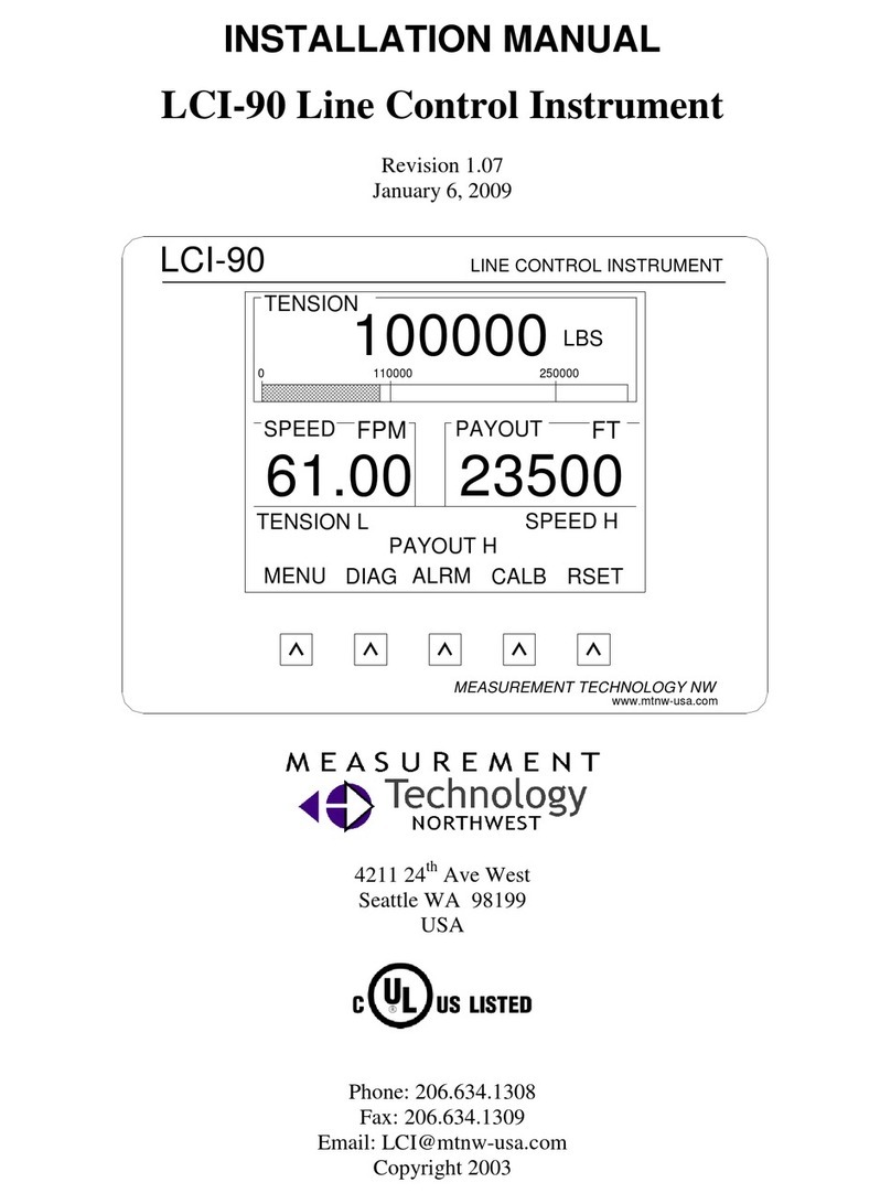
MEASUREMENT TECHNOLOGY LCI-100 User manual

INSTALLATION MANUAL
LCI-100 Line Control Instrument
Revision 1.02.B
November 20, 2000
LCI-100 LINE CONTROL INSTRUMENT
MEASUREMENT TECHNOLOGY NW
www.mtnw-usa.com
100000
TENSION
SPEED H
RSET
23500
LBS
61.00
PAYOUT H
TENSION L
DIAGMENU ALRM CALB
SPEED
0
PAYOUT
FPM
110000 250000
FT
Copyright 2000
Measurement Technology NW
4211 24th Ave West
Seattle WA 98199, USA
Phone: 206.634.1308
Fax: 206.634.1309
Email: LCI@mtnw-usa.com

Measurement Technology NW LCI-100 Operator Manual Page 2
Table of Contents
1.0 Overview.........................................................................................................................6
2.0 Quick Start......................................................................................................................7
2.1 Mounting...................................................................................................................... 7
2.2 Basic Field Wiring........................................................................................................ 7
2.3 Basic Hardware Configuration..................................................................................... 8
2.4 Basic Operation............................................................................................................ 8
3.0 Mechanical Installation...............................................................................................11
3.1 Environmental Considerations ................................................................................... 11
3.2 Dimensions and Cutout.............................................................................................. 11
3.3 Display Mounting....................................................................................................... 11
4.0 Options and Wiring Diagrams.....................................................................................12
4.1 Wiring Hookup –Local Display ................................................................................. 13
4.1.1 Display power and fuse..............................................................................................................................13
4.1.2 Tension Sensor Inputs ................................................................................................................................13
4.1.3 Count Sensor Inputs....................................................................................................................................16
4.1.4 Alarm Outputs.............................................................................................................................................18
4.1.5 Shunt Calibration.........................................................................................................................................18
4.1.6 Analog Outputs............................................................................................................................................19
4.1.7 Serial Communications..............................................................................................................................20
4.2 Wiring Hookup –LCI-90R Remote Display............................................................... 21
4.2.1 LCI-90R display power and fuse..............................................................................................................21
4.2.2 LCI-90R communication ports.................................................................................................................22
4.2.3 LCI-90R display brightness adjustment..................................................................................................23
5.0 Local Display Operation..............................................................................................24
5.1 Front Panel Identification........................................................................................... 24
5.2 Programming Menu................................................................................................... 25
5.3 Alarms........................................................................................................................ 26
5.3.1 Acknowledging alarms...............................................................................................................................27
5.3.2 Setting alarm limits.....................................................................................................................................27
5.3.3 Configuring Alarms ....................................................................................................................................28
5.4 Tension Calibration.................................................................................................... 29
5.4.1 Scale and offset............................................................................................................................................30
5.4.2 Two point live calibration..........................................................................................................................30
5.4.3 Look-up tables.............................................................................................................................................31
5.5 Tension Tare .............................................................................................................. 32
5.5.1 Tension Tare ................................................................................................................................................32
5.6 Shunt Calibration....................................................................................................... 33
5.6.1 Shunt Calibration.........................................................................................................................................33
5.7 Wrap Angle (single-input configurations)................................................................... 34
5.7.1 Wrap angle adjustments.............................................................................................................................34

Measurement Technology NW LCI-100 Operator Manual Page 3
5.8 Sensor Angle (two-axis input configurations)............................................................. 35
5.8.1 Sensor Angle Correction for Dual-Axis Load Pins...............................................................................35
5.9 Payout Calibration..................................................................................................... 36
5.9.1 Payout Scale.................................................................................................................................................36
5.9.2 Payout Preset...........................................................................................Error! Bookmark not defined.
5.10 Display Configuration................................................................................................ 36
5.10.1 Locating variables on screen.....................................................................................................................37
5.10.2 Setting display units....................................................................................................................................38
5.10.3 Setting decimal places................................................................................................................................39
5.10.4 Setting Bar Graph Range...........................................................................................................................39
5.10.5 Tension Display Smoothing......................................................................................................................39
5.10.6 Screen saver.................................................................................................................................................39
6.0 Hardware Configuration.............................................................................................40
6.1 Security...................................................................................................................... 40
6.2 Factory Setup............................................................................................................. 40
6.3 Analog Input Configuration....................................................................................... 41
6.3.1 Using Multiple Tension Sensors...............................................................................................................41
6.3.2 Sensor Input Check Alarm........................................................................................................................42
6.4 Analog Output Channels............................................................................................ 43
6.4.1 Calibrating the analog output signal........................................................................................................43
6.5 Alarm Configuration.................................................................................................. 44
6.5.1 Alarm types..................................................................................................................................................45
6.5.2 Alarm limits .................................................................................................................................................45
6.5.3 Alarm outputs..............................................................................................................................................45
6.6 Serial Communication................................................................................................ 45
6.6.1 Local/Remote operation modes................................................................................................................46
6.6.2 Programming remote displays..................................................................................................................47
6.6.3 AUX com port settings...............................................................................................................................47
6.6.4 Protocol descriptions..................................................................................................................................48
6.6.5 Polling Strings.............................................................................................................................................49
7.0 Remote Display Operation...........................................................................................50
7.1 Active Remotes –REM-A........................................................................................... 50
7.2 Blind Remotes –REM-B............................................................................................. 51
8.0 Troubleshooting...........................................................................................................52
8.1 DIAG screen operation............................................................................................... 52
8.2 Troubleshooting procedures....................................................................................... 53
8.3 Technical support....................................................................................................... 57
9.0 Appendix A –Dimensional Drawing...........................................................................58
10.0 Appendix B –Jumper Settings on Interface PCB –REV 1.......................................59
11.0 Appendix C –Analog Hardware Configuration.........................................................61
12.0 Appendix D –Interface PCB REV 1...........................................................................63
13.0 Appendix E –Wrap Angle Calculations.....................................................................64

Measurement Technology NW LCI-100 Operator Manual Page 4
14.0 Appendix F –Idealized Dual Axis Load Pin Geometry.............................................65
15.0 Appendix G –Non Idealized Dual Axis Load Pin Geometry.....................................66
16.0 Appendix H –LCI-100 Specifications.........................................................................67
17.0 Appendix I –LCI-90R Specifications.........................................................................70

Measurement Technology NW LCI-100 Operator Manual Page 5
Figures and Tables
Figure 1.1 –LCI-100 Front Panel............................................................................................. 6
Figure 2.1 –Power Hookup –DC Power ................................................................................. 7
Figure 2.2 –Tension Hookup –4 Wire 4-20 mA Signal.......................................................... 8
Figure 2.3 –Payout Hookup –2 Channel 12VDC Proximity Switch...................................... 8
Figure 4.1 –Identification of hardware options and manual sections by function................. 12
Figure 4.2 –Fuse rating and replacement part –Local display.............................................. 13
Figure 4.3 –Local Display Power Hookup –DC Power........................................................ 13
Figure 4.4 –Local Display Power Hookup –AC Power........................................................ 13
Figure 4.5 –Tension Hookup –3 Wire 4-20 mA Signal........................................................ 14
Figure 4.6 –Tension Hookup –4 Wire 4-20 mA Signal........................................................ 14
Figure 4.7 –Tension Hookup –2 Wire 4-20 mA Signal........................................................ 15
Figure 4.8 –Tension Hookup –4 Wire DC Voltage Input..................................................... 15
Figure 4.9 –Tension Hookup –4 Wire Strain Gauge ............................................................ 15
Figure 4.10 –Tension Hookup –Isolated 2 Wire 4-20 mA Signal........................................ 16
Figure 4.11 –Payout Hookup –12V NPN/PNP switches -Primary...................................... 16
Figure 4.12 –Payout Hookup –12V NPN/PNP switches –Secondary................................. 17
Figure 4.13 –Payout Hookup –TTL Encoder -Primary....................................................... 17
Figure 4.14 –Payout Hookup –TTL Encoder -Secondary................................................... 17
Figure 4.15 –Alarm Output Hookup –8 Channels ................................................................ 18
Figure 4.16 –Shunt Calibration Hookup ................................................................................ 18
Figure 4.17 –Non-isolated Analog Output Hookup............................................................... 19
Figure 4.18 –Non-isolated Analog Output Hookup............................................................... 19
Figure 4.19 –Isolated Analog Output Hookup –4 Channels ................................................. 20
Figure 4.20 –RS-485 Network Communcation Hookup ....................................................... 20
Figure 4.21 –Remote Display Fuse rating and replacement part........................................... 21
Figure 4.22 –Remote Display Power Hookup –DC Power .................................................. 21
Figure 4.23 –Remote Display Power Hookup –AC Power .................................................. 21
Figure 4.24 –LCI-90R Auxiliary RS-232 Hookup ................................................................ 22
Figure 4.25 –LCI-90R Network RS-232 Hookup.................................................................. 22
Figure 4.26 –LCI-90R Network RS485 Hookup ................................................................... 22
Figure 5.1 –LCI 100 Front Panel........................................................................................... 24
Figure 5.2 –LCI 100 Menu Tree ............................................................................................ 26
Figure 5.3 –Sample Alarm Message Display........................................................................ 27
Figure 5.4 –Digital Output Module Locations and Menu Names ......................................... 29
Figure 5.5 –LCI-100 Display Units ....................................................................................... 38
Figure 6.1 –Analog Output Module Locations and Menu Names......................................... 43
Figure 8.1 –Diagnostics Screen Display................................................................................ 52

Measurement Technology NW LCI-100 Operator Manual Page 6
1.0 Overview
The LCI-100 Line Control Instrument is a versatile instrument that displays line Tension, Payout,
and Speed for winch and wire rope applications. Signals from Tension and Payout sensors are
converted into engineering units and displayed on a high visibility electro-luminescent display.
The display and the five front panel keys underneath it allow the operator to acknowledge alarms
and to manipulate the calibration and configuration menus. The function of each key is indicated
by the label that appears immediately above it in the Display. As the operator navigates through
various displays the functions of these keys and their associated labels will change. The LCI-100
can be user configured to accept inputs from a range of Tension and Payout sensors, display the
parameters in different locations and resolutions, enable as many as six different alarms, and select
a variety of serial communication options.
This manual is intended to cover the installation, set-up, and operation of the LCI-100 and the
LCI-90R remote display.
LCI-100 LINE CONTROL INSTRUMENT
MEASUREMENT TECHNOLOGY NW
www.mtnw-usa.com
100000
TENSION
SPEED H
RSET
23500
LBS
61.00
PAYOUT H
TENSION L
DIAGMENU ALRM CALB
SPEED
0
PAYOUT
FPM
110000 250000
FT
Figure 1.1 –LCI-100 Front Panel

Measurement Technology NW LCI-100 Operator Manual Page 7
2.0 Quick Start
This section provides a subset of the full technical manual to facilitate installation and start-up of
the LCI-100. For a complete technical description please refer to Sections 3.0-6.0.
2.1 Mounting
The LCI-100 will fit in a 9.25 x 7.00” cutout, with a minimum of 5.5” depth clearance (see
Appendix A for dimensional drawing). The instrument is held in place with removable
panel clamps that screw to all sides of the display. Four clamps are included with each
display.
After sliding the display into the cutout, screw the four panel clamps on the sides of the dis-
play, with the flanged end of the clamp toward the panel, using two 10-32 machine screws
per bracket. Once the panel clamps are installed, tighten the jackscrews against the panel to
compress the LCI-100 gasket to seal against the panel. Lock the jackscrews with hex nuts
to prevent them from vibrating loose over time.
2.2 Basic Field Wiring
Basic field wiring connections for the LCI-100 are those required for power, the force
transducer, and the quadrature Payout sensors. The base unit LCI-100 (i.e. no options) is
shipped with hardware settings to accommodate the following field devices: one 4-20 mA
Tension signal and two PNP proximity switch inputs for Payout. The LCI-100 can be
connected to a broad range of field sensors; wiring connections for these are explained in
detail in Section 4.0.
DC power (and serial communications) connections are made to the printed circuit board
directly behind the display. Tension and payout inputs, alarm wiring and analog outputs go
to quick-connect style terminal blocks on the “interface PCB”. These blocks are referenced
by both a label indicating the function (‘analog’, ‘digital’), and by an ID number (‘TB2’) on
the top of the block.
The connection diagrams for the factory standard power input, Tension and Payout sensors
are shown in the tables below. The LCI-100 terminal blocks are listed on the left by func-
tion and number, and the field devices are listed on the right.
DC Power Connection
Power In Power: 18-36 VDC, 0.625 A
V+ DC +
V–DC –
Figure 2.1 –Power Hookup – DC Power

Measurement Technology NW LCI-100 Operator Manual Page 8
Direct Input –4-20 mA, Four Wire, Channel 1
TB AUX DC OUT Force Xducer: 4 Wire, 4-20 mA
24 VDC EXCITATION +
COM EXCITATION –
ANALOG
2CH1 HI SIGNAL +
1CH1 LO SIGNAL –
Figure 2.2 –Tension Hookup –4 Wire 4-20 mA Signal
TB DIGITAL Payout Sensors -Proximity Switch
31 V+ EXCITATION –SENSOR A
41 V+ EXCITATION –SENSOR B
32 A1 SIGNAL –SENSOR A
42 B1 SIGNAL –SENSOR B
34 COM COMMON –SENSOR A
44 COM COMMON –SENSOR B
Figure 2.3 –Payout Hookup – 2 Channel 12VDC Proximity Switch
2.3 Basic Hardware Configuration
The base unit LCI-100 (i.e. no options) will accommodate the field device wiring and input
devices shown in Section 2.2 above. No menu programming or hardware jumper changes
are necessary if these inputs are used. Setup procedures for alarms, analog outputs, input
isolation modules, and serial communication options are discussed in Sections 4.0-6.0.
2.4 Basic Operation
The LCI-100 base unit is configured at the factory to display Tension at the top of the
screen, both numerically and as an analog bar graph immediately underneath. Speed is
displayed in the middle on the left and Payout on the right, as shown on the cover. The
factory setting for units is pounds and feet. Tension and Payout have 0 decimal places,
while Speed has 1 (2 illustrated). Section 5.0 explains how to change these settings.
The calibration values for the Tension and Payout sensors must be set for each field applica-
tion. The following is a description of the simplest calibration for the anticipated sensors
described above. For complete instructions on the menu functions and calibration features
refer to Section 5.0.

Measurement Technology NW LCI-100 Operator Manual Page 9
To calibrate either the Tension or Payout sensors, just press the CALB button on the RUN
screen. This will bring up the 2.0 CALIBRATEdisplay. (Or press MENU to get the 0
MAIN MENU shown below, then select 2 CALIBRATION; this achieves the same result):
0MAIN MENU (Rev 1.xx)
1SET ALARMS
>2CALIBRATION
3DISPLAY CONFIGURATION
4SYSTEM CONFIGURATION
RUN UP DOWN ENT ESC
To calibrate the Payout sensor, use the UP and DOWN keys to align the pointer with menu
item 5PAYOUT SCALE, then press ENT to move to the input field. Now use the INCR ,
DECRand keys to change the value to the correct number of pulses per foot. (See §5.9
for details; the number of decimal places shown is adjusted to maintain four-digit accuracy.)
Pressing ENT will accept the new value, pressing ESC will restore the old value. Pressing
RUN saves the displayed value for future use and returns the instrument to RUN mode.
2.0 CALIBRATION
1TENSION (THREE METHODS)
2TENSION TARE OFF
3SHUNT CAL OFF
4WRAP ANGLE 120 DEG
>5PAYOUT SCALE .800 P/FT
6PAYOUT PRESET 0FT
DECR INCR ENT ESC

Measurement Technology NW LCI-100 Operator Manual Page 10
To calibrate the Tension sensor, select menu item 1 TENSION (THREE METHODS) to
move to the 2.1 TENSION CAL METHOD 1 menu shown below. Select Item 2 and enter
the full-scale Tension sensor output in pounds. Then select Item 3 and enter the Tension
offset in pounds. The ENTkey accepts the new value; the ESC key restores the old value.
Press RUN to save the new values for future use and to return to the RUN Screen display.
This completes the initial calibration of the instrument.
2.1 TENSION CAL METHOD 1
1CALIBRATION SCL/OFS
>2FULL SCALE 20000 LBS
3OFFSET 50 LBS

Measurement Technology NW LCI-100 Operator Manual Page 11
3.0 Mechanical Installation
The LCI-100 is designed for mounting on the front-panel of an electrical enclosure with a suitable
environmental rating. The sealed front face of the LCI-100 is made of 12 gauge stainless steel,
and the slotted rear cage is designed to promote heat transfer, facilitate field wire terminations, and
provide a purchase point for the panel clamps. The front face is 8.0” high x 10.0” wide; the total
depth is 5.5”.
3.1 Environmental Considerations
The front face of the LCI-100 is designed for NEMA 4X applications. It consists of a 316
stainless steel top layer, a sealed lexan window, and five membrane-sealed stainless steel
push buttons. The rear cage is NEMA 1 and requires protection with a suitable enclosure.
A polyurethane gasket, held in-place by a high temperature adhesive is applied to the back-
side of the front face. When mounting the LCI-100 in open deck locations, a front-panel
cover is recommended to protect the unit when it is not in use.
The standard temperature range of the LCI-100 is –20°C to +60°C. The high temperature
(HT) model will operate in temperatures from –40°C to +75°C.
An optional rear enclosure is available to provide NEMA 4X protection for the instrument.
The NEMA 4X enclosure can be mounted with an adjustable gimbal bracket. Consult
factory for mounting information and temperature ratings.
3.2 Dimensions and Cutout
The LCI-100 will fit in a 9.25” x 7.00” cutout (tolerance –0.01, +0.100), with a minimum of
5.5” depth clearance (see Appendix A for dimensional drawing). The front panel can be up
to 5/8” thick.
3.3 Display Mounting
The instrument is held in place with removable panel clamps that screw to the 10-32
threaded inserts on all sides of the display. Four clamps are included with each display, but
the unit can be installed using as few as two if a panel seal is not required.
Two hole patterns are available on each bracket. The bracket that is used on the bottom
edge of the unit will need to use the holes that are located closer to the bend of the bracket.
The remaining three brackets use the two holes located farthest from the bend.
After sliding the display into the cutout, screw the four panel clamps onto the sides of the
display, with the flanged end of the clamp facing toward the panel. Once the panel clamps
are installed, tighten the jackscrews against the panel to compress the LCI-100 gasket to
seal against the panel. Lock the jackscrews with hex nuts to prevent them from vibrating
loose over time.

Measurement Technology NW LCI-100 Operator Manual Page 12
4.0 Options and Wiring Diagrams
The LCI-100 can be configured for a wide range of signal input and output functions. Each
of these functions requires the instrument to have the correct menu settings (Section 5.0),
hardware jumper settings (Appendix C), signal and power wiring, and in some cases,
optional I/O modules installed. The wiring diagrams are given in this Section; the optional
I/O modules are listed in Appendix D. The table below gives of a summary of the LCI-100
functions, referenced to their associated menu, required hardware options, and section of
this manual covering the wiring termination.
Function Menu Number Std/Option # Wiring –Manual
Section
DC Power N/A Std 4.1.1
Analog Input
Direct 4-20 mA 4.2 Std 4.1.2
Analog Input
Direct DC
Voltage
4.2 Std 4.1.2
Analog Input
Isolated 4.2 21,22,23 4.1.2
Payout Sensor
Input 2.0 Std 4.1.3
Alarm Output 4.4 01,02,03,04 4.1.4
Analog Output
Direct 4-20 mA 4.3 30 4.1.5
Analog Output
Direct DC
Voltage
4.3 31 4.1.5
Analog Output
Isolated 4.2 32, 33 4.1.5
Serial Comm.
RS232, Network
4.5 10 4.1.6
Serial Comm.
RS485, Network
4.5 11, 12 4.1.6
Serial Comm.
RS232, Auxiliary
4.5 10 4.1.6
Figure 4.1 –Identification of hardware options and manual sections by function

Measurement Technology NW LCI-100 Operator Manual Page 13
4.1 Wiring Hookup –Local Display
This section provides wiring diagrams and related specifications for power and signal input
and output connections for the LCI-100.
4.1.1 Display power and fuse
The fuse, F1, is located on the rear panel of the display. Use a flat blade screwdriver
to open the cover for access. The replacement part is a 5 x 20 mm fuse rated accord-
ing to the system options. See the table below for fuse sizing.
Model No Fuse Rating Littlefuse Part No
LCI-100-DC 5/8 A 216.630
LCI-100-AC 1/2 A 216.500
Figure 4.2 –Fuse rating and replacement part –Local display
The LCI-100-DC requires an 18-36 Volt DC power source. The connection for the
power is shown below.
POWER IN Power: 18-36 VDC, 0.625 A
V+ DC +
V–DC –
Figure 4.3 –Local Display Power Hookup –DC Power
The LCI-100-AC requires an 85-265 Volt AC power source. The connection for the
power is shown below.
POWER IN Power: 85-265 VAC, 0.5 A
V+ VAC LINE
V–VAC NEUTRAL
GND VAC GROUND
Figure 4.4 –Local Display Power Hookup –AC Power
4.1.2 Tension Sensor Inputs
The Tension sensor analog inputs both isolated and non-isolated are terminated on
the bank of terminal blocks labeled Analog. The field wiring connects to the unit on
the rear and underside of the enclosure. Terminal blocks are referenced both by the
external label located underneath each bank of terminal blocks and by terminal block
numbers located on the top of the terminal block banks.

Measurement Technology NW LCI-100 Operator Manual Page 14
Isolated analog inputs require signal-conditioning modules. The optional analog
input modules (Appendix D) supply isolation and a variety of signal conditioning
options. The analog input channels 1 and 2 are factory configured to accept 4-20 mA
inputs while the remaining four channels are factory configured for 0-5 VDC voltage
inputs. The LCI-100 can accept six analog inputs, allowing the output from multiple
tension sensors to be summed. Each different input type requires a specific hardware
configuration setting (see Appendix C).
Tension sensors can be externally powered from the auxiliary DC output 24VDC
located on the barrier blocks mounted on the rear of the display. Option 43 must be
specified. The factory configuration internally connects the auxiliary DC output
COM to the CH (1-6) LO.
The LCI-100 can accept input from dual axis load pins on any two adjacent channels.
The first channel should be the x-axis input, the second channel should be the y-axis
input. Both channels must be configured for 2-AXISinput (see §6.3). Refer to §5.8
and §§14-15 (Appendices F & G) for more details about this configuration.
Below are the wiring diagrams for the different sensor types and excitation scenarios.
Direct Input –4-20 mA, Three Wire, Channel 1
TB AUX DC OUT Force Xducer: 3 Wire, 4-20 mA
24 VDC EXCITATION
ANALOG
2CH1 HI SIGNAL +
1CH1 LO SIGNAL –
Note: 24V COM internally connected to CH1 LO.
Figure 4.5 –Tension Hookup –3 Wire 4-20 mA Signal
Direct Input –4-20 mA, Four Wire, Channel 1
TB AUX DC OUT Force Xducer: 4 Wire, 4-20 mA
24 VDC EXCITATION +
COM EXCITATION –
ANALOG
2CH1 HI SIGNAL +
1CH1 LO SIGNAL –
Figure 4.6 –Tension Hookup –4 Wire 4-20 mA Signal

Measurement Technology NW LCI-100 Operator Manual Page 15
Direct Input –4-20 mA, Two Wire, Channel 1
TB AUX DC OUT Force Xducer: 2 Wire, 4-20 mA
24 VDC EXCITATION
ANALOG
2CH1 HI SIGNAL +
Note: 24V COM internally connected to CH1LO.
Figure 4.7 –Tension Hookup –2 Wire 4-20 mA Signal
Direct Input –DC Voltage, +24 Volt Excitation, Channel 1
TB AUX DC OUT Force Xducer: Voltage Output
24 VDC EXCITATION +
COM EXCITATION –
ANALOG
2CH1 HI SIGNAL +
1CH1 LO SIGNAL –
Figure 4.8 –Tension Hookup –4 Wire DC Voltage Input
Isolated Input –4 Wire Strain Gauge with Module
TB ANALOG Force Xducer: Strain Gauge
17 EXC1 HI EXCITATION +
16 EXC1 LO EXCITATION –
ANALOG
2CH1 HI SIGNAL +
1CH1 LO SIGNAL –
Note: 4 wire strain gauge module must be inserted in correct position.
Figure 4.9 –Tension Hookup –4 Wire Strain Gauge

Measurement Technology NW LCI-100 Operator Manual Page 16
Isolated Input –4-20 mA Isolated Process Current Loop with Module
TB ANALOG Force Xducer: Current Output
17 EXC1 HI EXCITATION +
ANALOG
2CH1 HI SIGNAL +
Note: 2 wire 4-20 process current loop module must be inserted in correct position.
Figure 4.10 –Tension Hookup –Isolated 2 Wire 4-20 mA Signal
4.1.3 Count Sensor Inputs
The count sensor inputs are terminated on the Digital terminal block bank. The LCI-
100 can accept NPN and PNP type proximity and Hall-Effect inputs, as well as TTL/
CMOS encoder inputs. The input voltage thresholds are set to accommodate all these
ranges with no adjustment. These thresholds are 3.4 Volts for low-high transitions,
and 2.3 volts for high-low transitions.
Each different sensor type requires a specific hardware jumper setting on the inter-
face PCB (see Appendix B). The LCI-100 can accept two separate quadrature
inputs. Below are the wiring diagrams for the different sensor types with typical
excitation voltages.
Dual NPN/PNP Switches, +12 V Excitation, Primary Channel
TB DIGITAL Payout Sensors –Proximity Switch
31 V+ EXCITATION –SENSOR A
41 V+ EXCITATION –SENSOR B
32 A1 SIGNAL –SENSOR A
42 B1 SIGNAL –SENSOR B
34 COM COMMON –SENSOR A
44 COM COMMON –SENSOR B
Note: Jumper settings must match sensor input and excitation.
Figure 4.11 –Payout Hookup –12V NPN/PNP switches -Primary

Measurement Technology NW LCI-100 Operator Manual Page 17
Dual NPN/PNP Switches, +12 V Excitation, Secondary Channel
TB DIGITAL Payout Sensors –Proximity Switch
31 V+ EXCITATION –SENSOR A
41 V+ EXCITATION –SENSOR B
33 A2 SIGNAL –SENSOR A
43 B2 SIGNAL –SENSOR B
34 COM COMMON –SENSOR A
44 COM COMMON –SENSOR B
Note: Jumper settings must match sensor input and excitation.
Figure 4.12 –Payout Hookup –12V NPN/PNP switches –Secondary
TTL Encoder, +5 V Excitation –Primary Channel
TB Digital Payout Sensors –Encoder
31 V+ + EXCITATION
32 A1 SIGNAL –SENSOR A
42 B1 SIGNAL –SENSOR B
34 COM –EXCITATION
Note: Jumper settings must match sensor input and excitation.
Figure 4.13 –Payout Hookup –TTL Encoder -Primary
TTL Encoder, +5 V Excitation –Secondary Channel
TB Digital Payout Sensors –Encoder
31 V+ + EXCITATION
32 A1 SIGNAL –SENSOR A
42 B1 SIGNAL –SENSOR B
34 COM –EXCITATION
Note: Jumper settings must match sensor input and excitation.
Figure 4.14 –Payout Hookup –TTL Encoder -Secondary

Measurement Technology NW LCI-100 Operator Manual Page 18
4.1.4 Alarm Outputs
The eight alarm outputs are terminated on the Digital terminal block bank. The LCI-
100 requires optional SM-type optically isolated output modules to implement the
alarm outputs. These are available in both solid state and hard contact types with a
variety of voltage and current ratings. The wiring diagram below matches the Opto
Module number with the corresponding terminal block designation on the Digital
terminal block bank. Note that the Input Check alarm (§6.3.2) also uses Opto 1,
and the Shunt Cal relay (§4.1.5, §5.6) uses Opto 8.
Alarm Outputs (8 channels total, channels 1, 2, 8 shown)
TB DIGITAL External Alarm/Device
47 OPTO 1+ ALARM 1 SIGNAL +
37 OPTO 1–ALARM 1 SIGNAL –
48 OPTO 2+ ALARM 2 SIGNAL +
38 OPTO 2–ALARM 2 SIGNAL –
………
54 OPTO 8+ ALARM 8 SIGNAL +
44 OPTO 8–ALARM 8 SIGNAL –
Note: Associated output modules must be installed in the correct position.
Figure 4.15 –Alarm Output Hookup –8 Channels
4.1.5 Shunt Calibration
The LCI-100 provides a method for “shunt calibration” of a load cell or load pin.
The sensor must have an internal relay that connects a precision resistor across one
leg of the bridge. The LCI-100 uses the Opto 8 output module to energize this relay.
Shunt Calibration Connections
TB DIGITAL Field Device
54 OPTO 8 + External Power +
44 OPTO 8 –Shunt Cal Relay (+)
Note: Shunt Cal relay must be referenced to external power common.
Figure 4.16 –Shunt Calibration Hookup

Measurement Technology NW LCI-100 Operator Manual Page 19
4.1.6 Analog Outputs
The LCI-100 provides two non-isolated analog outputs, or up to four isolated analog
outputs using signal conditioning modules. In both cases these outputs can be 4-20
mA, 0-5 Vdc, or 0-10 Vdc. Each different output type requires a specific hardware
jumper setting on the interface PCB (see Appendix B). Below are wiring diagrams
for the different output types.
Direct Output–2 Channels, Non Isolated
TB ANALOG Field Device
28 AOUT1 SIGNAL +
13 COM SIGNAL –
29 AOUT2 SIGNAL +
14 COM SIGNAL –
Note: Voltage or current output depends on jumper setting on CPU
Figure 4.17 –Non-isolated Analog Output Hookup
The 4-20 mA non-isolated analog outputs have the ability to be driven by either an
internal 15 Vdc power source or by an external power source (nominally 24 Vdc).
Units are factory configured for internal power. Below are the wiring diagrams for
the external option.
External Power to Drive Non-isolated 4-20 mA Analog Outputs
TB ANALOG External Power Source
30 EXT 24 VDC +
15 COM 24 VDC –
Figure 4.18 –Non-isolated AnalogOutput Hookup

Measurement Technology NW LCI-100 Operator Manual Page 20
Isolated Outputs (associated Module must be installed)
TB ANALOG Field Device/Data Logger
6CH3 HI CHANNEL 1 SIGNAL +
5CH3 LO CHANNEL 1 SIGNAL –
8CH4 HI CHANNEL 2 SIGNAL +
7CH4 LO CHANNEL 2 SIGNAL –
10 CH5 HI CHANNEL 3 SIGNAL +
9CH5 LO CHANNEL 3 SIGNAL –
12 CH6 HI CHANNEL 4 SIGNAL +
11 CH6 LO CHANNEL 4 SIGNAL –
Note: Associated output module must be installed in correct position and hardware
jumpers correctly configured.
Figure 4.19 –Isolated Analog Output Hookup –4 Channels
4.1.7 Serial Communications
The LCI-100 provides both RS-232 and RS-485 serial communication options with a
maximum of two ports. The base model has no serial ports. A RS-232 network port
can be added for data logging to a single remote device in close proximity. For long
cable runs or multi-drop applications, this option can be replaced by an electrically-
isolated RS-485 port. An auxiliary RS-232 port is also available for serial output to
user-supplied logging or display devices.
The RS-485 serial termination is set using the hardware jumper settings on the inter-
face PCB as shown in Appendix B.
The RS-232 network and auxiliary ports are accessed via 10-pin ribbon cable con-
nectors on the side of the unit. Cable pinouts are supplied with these options. The
wiring diagram for the RS-485 network port is shown below.
RS-485 Connection –2 Wire
NETWORK
RS485 Remote Device
T–/R–Network, T–/R–
SHLD Cable Shield
T+/R+ Network, T+/R+
Figure 4.20 –RS-485 Network Communcation Hookup
Table of contents
Other MEASUREMENT TECHNOLOGY Measuring Instrument manuals
Popular Measuring Instrument manuals by other brands

Omega
Omega SP-006 user manual

Optical dimensions
Optical dimensions LASER 5872C manual

Diamond Antenna
Diamond Antenna sx-1100 Operation instructions

NOVA BIOMEDICAL
NOVA BIOMEDICAL Max Creat eGFR Instructions for use

Center
Center 340 instruction manual

GESTRA
GESTRA NRT 2-1 Installation and service instructions