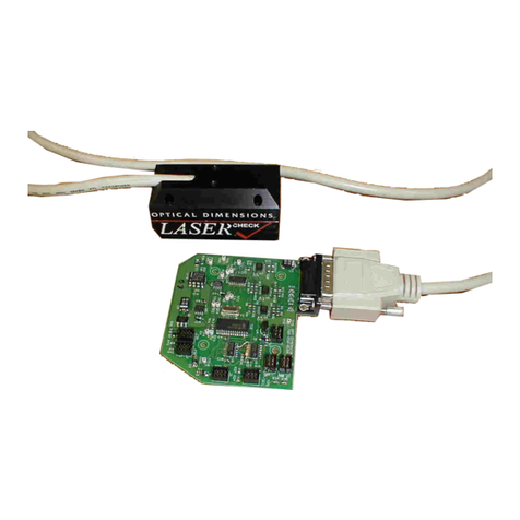
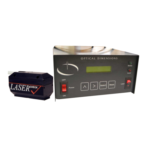
Optical dimensions LASER 5872C User manual

5872C Manual Version 5_4
LASER
CHECK
Surface Roughness
Measurement Gages
OPTICA
L
DIMENSIONS
LLC
®
1 3 7 E a s t A l t o n , S u i t e B
S a n t a A n a , C A 9 2 7 0 7
P H O N E : 7 1 4 - 6 6 8 - 9 1 1 5
F A X : 7 1 4 - 6 6 8 - 9 1 1 9
i n f o @ o p t i c a l d i m e n s i on s . c o m
w w w . o p t i c a l d i m e n s i o n s . c o m
®

LASER
CHECK
, , and Optical D i m e n s i o n s
LLC
are Registered Trademarks of Optical
Dimensions, LLC. The information in this document is provided as an aid in
the Assembly, Diagnostics, and Operation of the Lasercheck Gage, Components, and Accessories and is not
to be used otherwise or reproduced without written consent of Optical Dimensions, LLC. The Lasercheck
gage is patented technology protected under US Patent Number 5,608,527.
OPTICAL DIMENSIONS
LLC
®
1 3 7 E a s t A l t o n , S u i t e B
S a n t a A n a , C A 9 2 7 0 7
P H O N E : 7 1 4 - 6 6 8 - 9 1 1 5
F A X : 7 1 4 - 6 6 8 - 9 1 1 9
i n f o @ o p t i c a l d i m e n s i o n s . c o m
w w w . op t i c a l d i m e n s i o n s . c o m
®

i
TABLE OF CONTENTS
PERFORMANCE SPECIFICATIONS ...................................................................................................... 1
S
TORAGE
C
OMPUTER
R
EQUIREMENTS
......................................................................................................... 1
O
THER
F
EATURES
....................................................................................................................................... 1
SAFETY ........................................................................................................................................................ 2
E
LECTRICAL
................................................................................................................................................ 2
L
ASER
......................................................................................................................................................... 2
WARRANTY ................................................................................................................................................ 3
LIMITATION
OF
WARRANTY............................................................................................................... 3
C
USTOMS
S
TATEMENT FOR
R
ETURNING
L
ASERCHECK
E
QUIPMENT TO
O
PTICAL
D
IMENSIONS
.................... 3
MAINTENANCE ......................................................................................................................................... 4
C
LEANING THE
W
INDOW
............................................................................................................................. 4
A
SSISTANCE
................................................................................................................................................ 4
INTRODUCTION TO LASERCHECK..................................................................................................... 5
O
VERVIEW
.................................................................................................................................................. 5
SETTING UP THE INSTRUMENT........................................................................................................... 6
U
NPACKING
L
ASERCHECK
........................................................................................................................... 6
B
ASIC
C
ONNECTIONS
C
ONTROL
B
OX
.......................................................................................................... 6
Physical Mounting.................................................................................................................................. 7
Mounting Holes .................................................................................................................................. 7
S
OFTWARE
S
ETUP
........................................................................................................................................ 8
To Install Lasercheck Software from Windows 98, 2000, NT, or ME .................................................... 8
BASIC OPERATION USING CONTROL BOX PUSHBUTTONS ........................................................ 9
T
URNING THE
S
YSTEM
O
N
........................................................................................................................... 9
Main Screen............................................................................................................................................ 9
C
ONTROL
U
NIT AND
D
ISPLAYS
.................................................................................................................... 9
LCD Screen ............................................................................................................................................ 9
LCD Push Buttons .................................................................................................................................. 9
Highlighting...................................................................................................................................... 10
If Controller Does Not Respond to Pushbuttons............................................................................... 10
PERFORMING MEASUREMENTS ....................................................................................................... 11
O
PERATION
U
SING
W
INDOWS
S
OFTWARE
................................................................................................. 11
Control Box Setup File ......................................................................................................................... 11
Initiating a Measurement ..................................................................................................................... 11
Starting Software .............................................................................................................................. 11
Entering the Setup Module ............................................................................................................... 12
Setup for Lab System........................................................................................................................ 12
Changing the Display Control of the Setup File ............................................................................... 12
M
ANUAL
O
PERATION
................................................................................................................................ 13
Perform Measurements Module ........................................................................................................... 13
Measure Menu.................................................................................................................................. 13
Return ........................................................................................................................................... 14
Start .............................................................................................................................................. 14
Stop............................................................................................................................................... 14
Sequence....................................................................................................................................... 14
Save .............................................................................................................................................. 14

ii
Export ........................................................................................................................................... 15
A
UTOMATED
O
PERATION
.......................................................................................................................... 16
Numerous Continuous Measurements / Roll Grinding......................................................................... 16
Setting up Windows Software for External Inputs............................................................................ 16
Automatic Parameters for Automatic Start, Stop and Save Options................................................. 16
Individual Parts / Parts Inspection....................................................................................................... 18
Setting up Windows Software for External Inputs............................................................................ 18
Automatic Parameters for Automatic Start, Stop and Save Options................................................. 18
“Start” and “Stop” Sensor Wiring Inputs............................................................................................ 20
Triggering a measurement externally................................................................................................... 20
BEYOND THE BASICS ............................................................................................................................ 20
LASERCHECK ALIGNMENT PRINCIPLES AND PROCEDURES.................................................. 21
H
OW
D
OES
L
ASERCHECK
W
ORK
?............................................................................................................. 21
A
LIGNMENT
............................................................................................................................................... 22
Vertical ................................................................................................................................................. 22
Horizontal............................................................................................................................................. 23
Directional / Rotational........................................................................................................................ 23
M
EASURE
/H
EADTEST
D
IALOG
B
OX
........................................................................................................... 24
Measure/Headtest Screen A.................................................................................................................. 24
Measure/Headtest Screen B.................................................................................................................. 25
M
EASURE
/A
LIGN
D
IALOG
B
OX
................................................................................................................. 26
Horizontal Alignment with Measure/Headtest or Measure/Align ........................................................ 26
VERIFYING ALIGNMENT PROCEDURES ......................................................................................... 27
S
ET
H
EAD
C
LOSE
C
ORRECT
P
OSITION
....................................................................................................... 27
A
LIGN
H
ORIZONTALLY
.............................................................................................................................. 27
A
LIGN
V
ERTICALLY
................................................................................................................................... 27
V
ERIFY
A
LIGNMENT
.................................................................................................................................. 27
AIR KNIFE/SQUEEGEE ACCESSORIES ............................................................................................. 28
APPENDIX - SETUP FILES..................................................................................................................... 30
S
ETUP FILE FORMAT
................................................................................................................................... 30
FILENAME........................................................................................................................................... 30
START_INPUT ..................................................................................................................................... 30
RA_UNITS ............................................................................................................................................ 30
RA_THRESHOLD ................................................................................................................................ 30
CALIBRATION ..................................................................................................................................... 30
APPENDIX - CALIBRATION PROCEDURES ..................................................................................... 31
I
NSTRUCTIONS FOR USING THE
S
ETUP
F
ILE AND
C
ALIBRATION
T
EMPLATE
.
XLS
......................................... 31
Smooth and Rough Mode ..................................................................................................................... 31
Smooth Mode Measurements ........................................................................................................... 31
Rough Mode Measurements ............................................................................................................. 31
Calibration Spreadsheet....................................................................................................................... 31
Statistics and Accuracy......................................................................................................................... 32
Instructions for using the Setup File and Calibration Template.xls .................................................. 32
Step 1 Enter Ra Values................................................................................................................. 32
Stylus and Lasercheck Ra Values ............................................................................................. 33
Filename =................................................................................................................................ 34
Control =................................................................................................................................... 34
Units = ...................................................................................................................................... 34
Cal Type = ................................................................................................................................ 34

iii
Step 2 Mid Range ......................................................................................................................... 34
Adjust Max “X Value” / Adjust Min “X Value” ...................................................................... 34
Adjust Slope ............................................................................................................................. 35
Raise / Lower Curve ................................................................................................................. 35
Step 3 High Range........................................................................................................................ 35
Adjust Intercept ........................................................................................................................ 35
Adjust Exponential ................................................................................................................... 35
Step 4 Low Range......................................................................................................................... 35
Adjust Exponential ................................................................................................................... 36
Step 5 Review............................................................................................................................... 36
Step 6 Export Setup File............................................................................................................... 37
Export “File Transfer” or “Manual Input” Setup File............................................................... 38
Typical “File Download” Calibration Setup File...................................................................... 38
Typical “Manual Input” Calibration Setup File........................................................................ 38
Calibration Coefficients........................................................................................................ 38
Break Points.......................................................................................................................... 38
Threshold.............................................................................................................................. 39
RA_UNITS........................................................................................................................... 39
APPENDIX - INPUT AND OUTPUT PINOUTS .................................................................................... 40
I
NPUT
:
9-P
IN
F
EMALE
D-
SUB
C
ONNECTOR
................................................................................................ 40
Internal Opto relay:.............................................................................................................................. 40
Trigger pins:......................................................................................................................................... 40
Power pins:........................................................................................................................................... 40
Internal Opto relay Schematic: ............................................................................................................ 40
Typical Wiring Example:...................................................................................................................... 41
1)
Using Unpowered Switches for inputs:................................................................................. 41
2)
Using Powered Triggering Device (e.g. Proximity Sensors) for Inputs:............................... 41
Recommended Proximity Sensor Specifications: ......................................................................... 41
O
UTPUT
:
9-P
IN
F
EMALE
D-
SUB
C
ONNECTOR
............................................................................................ 42
1)
Output Schematic Ra_Limit...................................................................................................... 42
a)
Normal State – Surface Within Ra_Limit – in Spec ................................................................. 42
b)
Surface Outside Ra_Limit – out of Spec............................................................................... 42
2)
Output Schematic Analog_Out ................................................................................................. 42
a)
0-10V........................................................................................................................................ 42
b)
4-20mA................................................................................................................................. 42
APPENDIX - FILE MANAGEMENT ...................................................................................................... 44
F
ILE
S
YSTEM
W
INDOW
.............................................................................................................................. 44
Send Command..................................................................................................................................... 44
Receive Command ................................................................................................................................ 45
Delete Command .................................................................................................................................. 45
Reset Command .................................................................................................................................... 46
Exit Command ...................................................................................................................................... 46
S
ETUP
F
ILES
.............................................................................................................................................. 46
Creating Setup Files............................................................................................................................. 46
APPENDIX - UPGRADING CONTROLLER SOFTWARE................................................................. 47
P
REPARE
C
ONTROLLER
............................................................................................................................. 47
P
REPARE
C
OMPUTER
................................................................................................................................. 47
P
ERFORM
T
RANSFER
................................................................................................................................. 47
F
INISH
....................................................................................................................................................... 48

1
Performance Specifications
Measurement / Detection Method
Angle resolved laser scattering
Measurement speed
Single measurement in < 0.5 seconds
Measurement range
1.00 µinch to 80 µinch / 0.012 µm to 2.0 µm
Repeatability
± 3.0% of measured value
Spot size (area-measured)
5 mm X 1 mm
Environmental considerations (temperature / humidity):
Operating
-10ºC to +55º C / 10% to 90% RH
Storage
-40ºC to +80º C / 1% to 99% RH
Power requirements
110 VAC, 50 / 60 HZ, 2.0 Amps max.
Storage Computer Requirements
Windows 98, 2000, NT, or ME
Available serial port
Other Features
Works on any material/color (rubber, glass, steel, etc.)
RS232 Interface to upload and store data
Input Triggering: Start, Stop, and Save Measurements
User Configurable Failed Part Trigger Output
User Configurable Analog (0-10 Volt or 4-20 mA Current Loop) Output
Stored and printed items:
Roughness Plot
Date and Time
Average Ra Roughness and Standard Deviation
Minimum / Maximum Ra Roughness
ASCII Formatted File
Individual Measurement Values

2
SAFETY
Electrical
Lasercheck has been designed as a sealed and enclosed system. Voltages to operate the measurement head
are low (0 to +5 Volts) to minimize shock hazard. A power supply in the control unit converts 110/220 Volt
AC from a wall receptacle to low regulated DC voltages that power the system. High voltages are present
and they are dangerous. Lasercheck should never be run with the control unit open as it exposes operators
to hazardous voltages.
Laser
At the corner of the control unit is a labeled laser on/off switch. Turning this to the on position provides
power to the internal laser. A red LED above the switch is illuminated when the laser is operational. The
laser used in Lasercheck is a class II laser device. Class II lasers are not considered hazardous to the skin
but are considered a “chronic viewing hazard”. Users should not stare directly into the beam or directly into
the beam reflected off a smooth specular surface. The ends of the Lasercheck measurement head have
“Caution” and “Avoid Exposure” labels to remind the operator to avoid exposure to the radiation. The head
also has “Identification” and “Certification” labels. The Lasercheck control unit also has”Identification” and
“Certification” labels. Reproductions of these labels are shown below.
Caution – use of controls or adjustments or performance or procedures other than those specified herein
may result in hazardous radiation exposure.
The measurement head emits a red visible (650-nm) laser beam pulsing at a 10 to 50 Hz. Each “pulse”
contains as much as 90 microjoules of energy. Pulses can be as short as a 5 millisecond interval, with 20
microsecond rise and fall times. Maximum “peak” power can be as high as 2.0 milliwatts. Average
maximum power being emitted from the laser can be as high as 900 microwatts. Once the beam strikes the
measurement surface, the laser energy is reflected back into the Lasercheck detection system. However,
multiple reflections and stray light may exit from between the head and measurement surface and care
should be taken to avoid direct eye exposure to the radiation.
Figure 1 – Typical Laser Identification and Warning Labels
CAUT
I
ON
DO NOT
STARE DIRECTLY INTO BEAM
LASER RADIATION
650 nm – 0.9 mW MAXIMUM OUTPUT
90 uJ per pulse @ 10 Hz
CLASS II LASER PRODUCT
CAUTION
LASER RADIATION
DO NOT STARE DIRECTLY INTO
BEAM
650 nm – 0.9 mW MAXIMUM OUTPUT
90 uJ per pulse @ 10 Hz
CLASS II LASER PRODUCT
O P T I C A L D I M E N S I O N S
137 East Alton, Suite B Model 5872
Santa Ana, CA 92707 Serial #
Mfg Date:
Complies with21 CFR 1040.10 and 1040.11
U.S. Patent No. 5,608,527
O P T I C A L D I M E N S I O N S
LLC
137 East Alton, Suite B Model 5872
Santa Ana, CA 92630 Serial #
Mfg Date:
Complies with 21 CFR 1040.10 and 1040.11
U.S. Patent No. 5,608,527
DO NOT STARE INTO BEAM
LASE
R
RADIA
TION
CLASS II LA
SER PRODUCT
650 nm – 0.9 mW MAXIMUM
AVERAGE OUTPUT
CAUTIO
N
AVOID EXP OSU RE
LASE R RADI ATI ON EMITTED
FROM THIS APERTURE

3
WARRANTY
Optical Dimensions, LLC certifies that the Model 5872 Lasercheck surface roughness measurement system
meets specifications. The Lasercheck system has a warranty period of 30 days, extended to one (1) year
upon receipt of full payment according to the terms specified on the invoice. This warranty is against
defects in material and workmanship. During the warranty period, Optical Dimensions will, at its option,
either repair or replace products, which prove to be defective.
LIMITATION OF WARRANTY
This warranty will not apply to defects resulting from improper or inadequate maintenance by Buyer (please
refer to Maintenance section), unauthorized modification or misuse, operation outside the environmental
specifications, improper site preparation or site maintenance, fire, flood earth movement or collapse.
Optical Dimensions shall not be liable for any direct, indirect, special, incidental or consequential damages,
whether based on contract, tort, or any other legal theory. No other warranty, whether expressed or implied,
will be valid.
For warranty service or repair, the Lasercheck system must be returned to Optical Dimensions, Santa Ana,
CA after prior authorization has been obtained from Optical Dimensions. Buyer shall prepay shipping
charges to Optical Dimensions. Optical Dimensions will pay shipping charges to return the Lasercheck
system to the Buyer.
Customs Statement for Returning Lasercheck Equipment to
Optical Dimensions
Overseas Buyers are to pay all shipping charges, taxes, and duties to Optical Dimensions. Optical
Dimensions will not pay customs and duties charges on returns. Returns must include required paperwork.
Incorrectly labeled and incorrectly prepared shipping and customs documents will result in delays to
equipment being returned to customer.
The following statement should be on all customs invoices and documents:
“The articles are manufactured in the United States. They were exported from the United States, from the
port of Los Angeles on or about (insert approximate month and year). They are being returned for (insert
the most appropriate statement below)”:
a) No charge warranty repair (or No charge warranty replacement).
c) Repair/service by manufacturer.
Also on the Air Waybill label there is usually a box for "Declared Value for Customs". If it is being
returned for a “no charge warranty”, list $O as value, AGR (American Goods Returned) in the box. Or to be
more clear "$0 - Warranty" if there is space in the box. If it is being returned for an out of warranty repair,
put $0 in that box. When we return it, $xx (the cost of the repair) will be on the paperwork. At that time,
any required duties on repair costs will be applied. On the International Waybill, mark under type of export
"RETURN" and "TEMPORARY". With that being done, it shouldn’t incur and DUTY charges but it still
may incur customs clearance fees
DO NOT put the original price of the instrument on any packing lists or shipping labels or customs
paperwork that accompanies the shipment. This can result in excessive duty charges being applied. Any
customs / duty charges will be charged to the customer.
Applying these statements, following these procedures and always using “no charge”, $0, or only the dollar
amount of the repair will help to avoid customs and duties fees being applied to the unit being returned for
repair or at least restrict customs and duties being applied to the value of the repair work or service only.

4
MAINTENANCE
Lasercheck has been designed and assembled by skilled and experienced engineers and technicians. All
components used in the system operate well within their rated specifications to ensure long life and
reliability of the Lasercheck system. Electronics, lasers, and detectors are all solid-state devices and should
not need to be serviced or maintained by the user.
The controller housing is made from impact-resistant ABS and is colored black. The housing is not
waterproof, but it can be subjected to moderate rain or splash without harm.
The laser head is made of machined aluminum and plastic and all electronics and optics are secured and
sealed within the head. The head is rugged enough to withstand handling that might be normally
encountered in manufacturing shop floor gage operation. The head is also water resistant and can be
subjected to moderate rain or splash without harm.
Boards and electronics used in the system are static sensitive and easily damaged by mishandling. The
Lasercheck housing and electronics are well grounded. The head is sealed at all seams and holes to protect
components from external contaminants. The user should not open the measurement head. If opened without
prior authorization by Optical Dimensions, the warranty provided by Optical Dimensions will be void.
Cleaning the Window
The internal optics and electronics are cleaned during assembly and kept within the sealed head. The
outside windows at the bottom of the Lasercheck head will be exposed to outside contaminants and should
be cleaned at least weekly with more frequent cleanings in very dirty environments. Dust and light visible
films will not affect Lasercheck performance on rougher surfaces, but on very smooth surfaces (1 to 2
µinches or smoother), even light films and dust can affect performance and should be cleaned off
frequently.
The windows are rugged, but care needs to be taken to not scratch them during operation or cleaning. They
should only be cleaned with ethanol, methanol, or a glass cleaner and a soft, clean paper towel, tissue, or Q-
tip.
Assistance
Optical Dimensions, LLC
137 East Alton, Suite B
Santa Ana, CA 92707
Tel: 714-668-9115
Fax: 714-668-9119

5
INTRODUCTION TO LASERCHECK
Overview
Lasercheck is designed to perform high speed, accurate, non-contact measurements of surface roughness. A
built in visible laser diode emits a laser beam from the bottom of the gage illuminating the surface beneath
it. After striking the surface, the laser light is reflected and scattered back into the Lasercheck detection
system. The overall intensity and distribution of the reflected and scattered light is measured, digitized by
Lasercheck electronics, and then Ra roughness is calculated for the illuminated area. This Ra value is then
displayed on the LCD screen of the Lasercheck control unit. The Lasercheck Windows display and control
software can be used to display the real time Ra values in graphical and numeric format along with
statistical parameters.
Lasercheck has been designed for a nominal height standoff of 1.055 inch ±0.01 inches from the
measurement surface. Motions and vibrations within that tolerance range are monitored continuously and
reflectance and scatter distribution are normalized and corrected during every measurement cycle to ensure
accurate results. Surfaces are positioned 1.055 inches below the gage allowing non-contact measurements of
the surface to be made.
Measurements can be performed by manual pushbutton operation, or continuous high-speed measurements
controlled by Windows software, or fully automated high speed on-line measurements triggered by external
signals and the Windows software. At the end of a measurement sequence, the user is provided options for
performing additional measurements, saving the current measurements or exiting the measurement
sequence. When measurements are saved an ASCII file format can be created for reading into a variety of
spreadsheet and analysis software packages.

6
Setting up the Instrument
Unpacking Lasercheck
All components of Lasercheck have been inspected and tested individually and as a system before shipping.
You should find the following items with your system:
1) Lasercheck measurement head.
2) Standoff (0.100”) plate (typically attached to measurement head)
3) Lasercheck control unit
4) 110 Volt Power Device Cable
5) RS232 serial null modem computer cable.
6) CD or 3.5 inch floppy disk with Lasercheck Calibration & Setup Files, Plus Manual
Measurement Head Control Unit
Basic Connections Control Box
Rear Panel of Box Front Panel of Box
Attach the power cable to the “110/220VAC” plug and then connect to 110/220 Volt Power Source.
The control unit has a DB15 connector labeled “Sensor” which mates to the connector end of the
measurement head cable. The cable should be secured with the thumbscrews on the cable.
The computer cable provided is a serial null modem variety. Standard serial connector adapters (25 to 9
pins, male to female etc.) can be used with these cables as necessary without affecting the null modem
capability. The Lasercheck control unit has a 9-pin serial connector port for attaching one end of the cable
(labeled RS232.) The connector should be screwed on to ensure strength and integrity during operation. The
other end should be attached to an available serial port on your host computer. Be sure that port has been
set up as COM1 to COM4 in your computer.
OPTICAL DIMENSIONS
LLC
LASER
CHECK
Printer
RS232
Keyboard
Monitor
RS485
110/220 VAC
Reset
Output
Input
Sensor
OFF
ON
Laser
Status
Pow
Laser
Select
Meas
>
^
OPTICAL DIMENSIONS
LLC

7
Note: During manual pushbutton measurement operation this computer connection is not required or used.
This connection is used for transferring saved measurement files to a host computer for storage or input into
SPC, spreadsheet, or other data analysis software or for automated measurements taken with Optical
Dimensions Windows software.
The start and stop inputs must have a female DB9 connector. They should be connected to the connector on
the control box labeled “Input”. These would only be used during “automatic operation”. Note: not
available on some versions.
Analog (0-10 Volt or 4-20 mA Current Loop) or indicators for “out of spec” surfaces must have a DB9
connector. They should be connected to the connector on the control box labeled “Output”. These would
typically be used during “automatic operation”. Note: not available on some versions.
Physical Mounting
The Lasercheck head is designed for two different mounting methods - suspension utilizing mounting holes
provided on the side of the box with optional X-Y-Z head mount, and optional mounting “feet” for bench
top operation.
Mounting Holes
Lasercheck is provided with four 10-32 mounting holes (Labeled “C” in the image below) on both sides of
the measurement head. The holes are positioned so that mounting bolts can be threaded into them without
interfering with any of the electronics inside the head. The holes are provided on both sides so that a
suspension mounting can be utilized for extra strength and balance. There should be capability for vertical
adjustment of the Lasercheck relative to the surface once installed for fine alignment purposes plus
horizontal or rotational adjustment. The optional X-Y-Z head mount from Optical Dimensions provides the
required adjustment flexibility.
Side View of Lasercheck Head Showing Four Mounting Hole Locations
The Lasercheck head has been assembled with sealant around all holes and seams to protect internal
components from contaminants. We recommend the use of RTV (Room Temperature Vulcanizing) silicon
adhesive sealant around the mounting holes or directly on the threads themselves. This will seal these holes

8
from the outside. This form of seal will be “breakable” or removable should you wish to later remove this
mounting and use the Lasercheck in a different process.
An understanding of alignment principals of Lasercheck is required for development of fixturing. Please
read the section “LASERCHECK ALIGNMENT PRINCIPALS AND PRECEDURES” later in this manual
to understand principals of alignment.
When performing measurements, set the rotational orientation so that the long axis of the head is
perpendicular to the dominant “lay” of the surface that you wish to measure. The long axis of the head
determines the direction of measurement in the same way that the direction of motion of a stylus on a stylus
gage determines the direction of measurement.
Software Setup
Lasercheck uses two different software packages. The control unit has software that initializes electronics,
controls the LCD screen, monitors the laser, reads detector signals, and calculates the alignment and surface
roughness. It also saves measurements in ASCII format files. This software comes pre-installed inside the
control unit. It is designed to auto load and auto execute whenever the “on / off” switch is turned on.
A CD or floppy disk with the Windows display and control software program, calibration & setup files, plus
the manual is provided. This software is installed on a separate computer. The Windows software uses the
included serial null modem cable to communicate with the control unit. It displays real time data to the user,
and transfers files to and from the control unit
To Install Lasercheck Software from Windows 98, 2000, NT, or ME
1) Insert Lasercheck CD or disk into the appropriate drive.
2) Click on the Start button. From the Start menu, choose Run.
3) Click on Browse button.
4) Select “appropriate drive letter:”
5) Double click on 5872 setup.exe.
6) Finally, click on Finish button.

9
Basic Operation Using Control Box Pushbuttons
Once the cables are attached and measurement head is mounted and aligned, you are ready to perform a
measurement. Lasercheck is run from the control unit keypad and LCD screen or optionally the Windows
software on the host computer. Detailed instructions on specific setups and operations can be found in the
software users manual. Following is an abbreviated description for setup and performance of a measurement
sequence.
Turning the System On
The control unit has a main on/off power switch. The control box provides regulated DC power to the
Lasercheck head. The control unit also powers the internal electronics, and automatically loads and
executes software internal to the controller.
Main Screen
When the main power switch is turned to the “on” position the internal electronics will turn on and software
will begin executing. During this startup period you will see will see the words displayed on the LCD
screen:
Once the electronics and software are fully executed, you will see the LCD screen display:
Or the current version of the software will be displayed. After 2 seconds, the LCD screen display will
change to the Main Screen:
The system is now ready to perform measurements. The control unit also has a second non-backlit on/off
switch. This must be turned to the on position to provide power to the internal laser. A red LED above the
switch is illuminated when the laser is operational.
Control Unit and Displays
LCD Screen
The Lasercheck Sensor Control Box has a 2 row, 16-column LCD screen. There are also 4 push button
inputs to control measurements, data storage, and data transfer.
LCD Push Buttons
The four push buttons are labeled as following (in the following order left to right) and are for:
^
Switch highlight between options
>
Scroll through options
Select
Select highlighted option
Meas
Take measurement at any time from main or measure windows
Lasercheck
Please Wait
Lasercheck
Version 14.43
SELECT:>GRIND_ST
^System:

10
Highlighting
The “^”, “>”, and “Select” buttons on the front panel of the Lasercheck are used to highlight and select
desired options. Pushing the “
^
” push button on the front panel switches which main menu is ACTIVE and
highlighted in CAPITAL letters. Options in that highlighted menu can be scrolled through are with a “>” on
the LCD screen. To choose an option, the “Select” button is pushed. The option that appears in to the right
of the menu in CAPITAL letters on the LCD screen is then selected. For example the main screen looks
like:
Pushing the “^” button will highlight the System menu instead of the Select menu that is currently
highlighted to change the screen to:
Pressing the “Select” button will select the files option from the System menu.
Changing options in the highlighted Files menu is done by pressing the “>” button. Pushing the “>” button
once shows:
If Controller Does Not Respond to Pushbuttons
The automated Lasercheck controller is designed to work under external computer control or under control
of the front panel pushbuttons. This is determined by configuration of an internal (user selectable) setup file
inside the control box. When a setup file configured to respond to an external computer through the serial
RS232 connector on the back of the control box is active, the system will not respond to the front panel
pushbuttons.
It takes about one second for the serial port to take control away from the pushbuttons when a “serial” based
setup file is active. In fact, sometimes the controller may just come up with a “serial” based setup file
displayed when you start the system making it difficult to ever get control of the pushbuttons. The solution
is to fairly rapidly push either of the scroll (> or ^) pushbuttons as the “serial” based setup file appears. You
can get the unit to briefly respond and scroll past a “serial” based setup file if you do it quickly and this will
allow you control of the unit through the pushbuttons so that you can do routine measures, file maintenance,
transfers and so on.
SELECT>GRIND_ST
^System:
^Select
SYSTEM: >files
Manage files:
FILES: >Send
Manage files:
FILES: >Receive

11
Performing Measurements
Once the measurement head is mounted and aligned, the cables attached, and the software is installed in the
host computer you are ready to perform a measurement. Lasercheck is set up and run from the Windows
software on the host computer. Detailed instructions on specific setups and operations can be found in the
software users manual. Following is an abbreviated description for setup and measurement.
Operation Using Windows Software
The Lasercheck can also be used and controlled through the Lasercheck windows software. For a detailed
explanation of using the Lasercheck windows software see the included software manual. A PDF version of
the software manual can be found under the C:\Program Files\Lasercheck directory created by the
installation program. The following is just a simple example of using the basic features of the windows
software.
Control Box Setup File
Using the “>” button on the control box scroll to a setup file that is set up for serial communication.
Instructions on changing screens is in the section named “Control Unit and Displays” in this manual. The
Control Box should be loaded with a proper setup file so that it is ready to communicate with the windows
software. This setup file tells it to take all its commands from the windows software on the host computer
through the serial port. If there is no setup file on the control box configured for “serial” communication
with a PC, use the Setup File and Calibration Template.xls to create a setup file with the line in the file:
“START_INPUT= SERIAL”
For instructions about how to create or edit a setup file see the section in this manual under “Appendix -
Calibration Procedures”. For instructions about how to load a setup file into the control box see the section
in this manual under “File Management / Receive Command”.
Initiating a Measurement
Starting Software
Make sure the Lasercheck system is connected correctly and powered on. For more detail on doing this
refer to the “Setting Up the Instrument” section in the beginning of the manual. Next start the Lasercheck
Windows Software Program. Click on the Start button, choose Programs, and then Lasercheck. Then
choose Lasercheck Windows Program.

12
Entering the Setup Module
From the main window of the Lasercheck software select the “Setup” push-button. This invokes the
“Password Entry” dialog box. Enter the password “4956”, and click OK.
Setup for Lab System
Under the Setup menu, select “Setup” and “Automation Type”. Select Lab System so that the software can
be used to control the measurement process.
Changing the Display Control of the Setup File
Under the Setup menu, select Open, and pick a setup file to modify. Use “Uncal.stp” to start with. Select
the “Display/Control” button and configure the X Scale to be from 1 to 100 and the Y Scale to be from 0 to
100 to assure that measurements will display within the graph window properly. This can be edited later to
values that best display the typical operation range. Set the Control Limits to the specification range you
would like the graph to display in green; outside these specification limits the graph will display in red. Use

13
the “Units” drop down box to select roughness displayed in Microns, Microinches, Nanometers, or
Angstroms of roughness . Other display options are described in the software manual.
Select “OK”. Now save the modified setup file by clicking “Save Setup” and renaming it to “filename.stp”.
Manual Operation
Perform Measurements Module
From the main window of the Lasercheck software select the “Perform Measurements” push-button. This
invokes the “setup/open” dialog box.
When Lasercheck software is first installed on your computer, sample setup files (*.STP) are loaded on
your computer in the C:\Program Files\Lasercheck directory. Select one of the pre-loaded setup files or any
new setup files that you have created or saved. A “Setup Information” dialog box will appear verifying your
setup file selection. If correct, select “OK”.
Measure Menu
Under the menu item “Measure”, select the option “Measure”. This creates an empty
graph screen with a run menu.

14
Return
Selecting “Return” from the Run Menu at any time closes the current graph and returns you to the “Measure
Menu”.
Start
Selecting “Start” from the Run Menu starts the Lasercheck and the graph begins displaying roughness
information. A graph of roughness vs. reading number will begin appearing in real time on the screen. In
addition, statistics of all measurements will be displayed digitally in real time at the top left and right
corners of the graph, and the current measurement in the top center of the graph.
Stop
While the roughness display is running, the Stop menu selection can be used to stop the data acquisition.
Selecting Start will restart the display. The “Stop / Start” cycle can be repeated as many times as is
necessary for the measurement set.
Sequence
While the roughness display is running, the Sequence menu selection can be used to restart a fresh data
acquisition cycle.
Save
The Save menu selection will provide a Windows “Save As” dialog box prompting the user to enter a
filename to save the data. Lasercheck software automatically attaches a Lasercheck “.LSC” data file
extension to the file name that is typed in. This data file can be opened for review in the Review Data
module from the main screen of the software.

15
After saving the measurement, you will be returned to the data graph screen and the new filename you have
created will be present in the upper right corner of the graph.
Export
Export can be used to export a text format file of the data named “Lasrdata.txt” to the active directory on
your computer.
Table of contents
Other Optical dimensions Measuring Instrument manuals