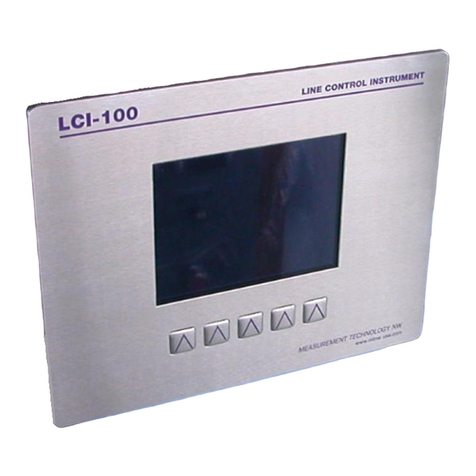
MEASUREMENT TECHNOLOGY LCI-90 User manual

INSTALLATION MANUAL
LCI-90 Line Control Instrument
Revision 1.07
January 6, 2009
LCI-90 LINE CONTROL INSTRUMENT
www.mtnw-usa.com
MEASUREMENT TECHNOLOGY NW
TENSION LBS
100000
0 250000
SPEED PAYOUT
61.00 23500
FTFPM
MENU DIAG ALRM CALB RSET
TENSION L PAYOUT H
110000
SPEED H
4211 24th Ave West
Seattle WA 98199
USA
Phone: 206.634.1308
Fax: 206.634.1309
Email: LCI@mtnw-usa.com
Copyright 2003

Measurement Technology NW LCI-90 Operator Manual Page 2
Table of Contents
1.0 Overview......................................................................................................................... 6
2.0 Quick Start...................................................................................................................... 7
2.1 Mounting................................................................................................................................ 7
2.2 Basic Field Wiring................................................................................................................. 7
2.3 Basic Hardware Configuration ............................................................................................ 8
2.4 Basic Operation ..................................................................................................................... 8
3.0 Mechanical Installation............................................................................................... 11
3.1 Environmental Considerations........................................................................................... 11
3.2 Dimensions and Cutout....................................................................................................... 11
3.3 Display Mounting................................................................................................................ 11
3.4 Ventilation Requirements................................................................................................... 11
3.5 Cleaning Instructions.......................................................................................................... 11
4.0 Options and Wiring Diagrams..................................................................................... 12
4.1 Wiring Hookup – Local Display......................................................................................... 13
4.1.1 Display power and fuse................................................................................................................ 13
4.1.2 Tension Sensor Inputs.................................................................................................................. 13
4.1.3 Count Sensor Inputs..................................................................................................................... 16
4.1.4 Alarm Outputs ............................................................................................................................. 17
4.1.5 Shunt Calibration......................................................................................................................... 19
4.1.6 Analog Outputs............................................................................................................................ 19
4.1.7 Serial Communications................................................................................................................ 20
4.2 Wiring Hookup – LCI-90R Remote Display..................................................................... 21
4.2.1 LCI-90R display power and fuse................................................................................................. 21
4.2.2 LCI-90R communication ports.................................................................................................... 22
4.3 Display brightness adjustment........................................................................................... 23
5.0 Local Display Operation.............................................................................................. 24
5.1 Front Panel Identification................................................................................................... 24
5.2 Programming Menu............................................................................................................ 25
5.3 Alarms .................................................................................................................................. 26
5.3.1 Acknowledging alarms ................................................................................................................ 27
5.3.2 Setting alarm limits...................................................................................................................... 27
5.3.3 Configuring Alarms..................................................................................................................... 28
5.4 Tension Calibration............................................................................................................. 29
5.4.1 Scale and offset............................................................................................................................ 30
5.4.2 Two point live calibration............................................................................................................ 30
5.4.3 Look-up tables ............................................................................................................................. 31
5.5 Tension Tare........................................................................................................................ 32

Measurement Technology NW LCI-90 Operator Manual Page 3
5.5.1 Tension Tare................................................................................................................................ 32
5.6 Shunt Calibration................................................................................................................ 33
5.6.1 Shunt Calibration......................................................................................................................... 33
5.7 Wrap Angle (single-input configurations)......................................................................... 34
5.7.1 Wrap angle adjustments............................................................................................................... 34
5.8 Sensor Angle (two-axis input configurations)................................................................... 35
5.8.1 Sensor Angle Correction for Dual-Axis Load Pins...................................................................... 35
5.9 Payout Calibration.............................................................................................................. 36
5.9.1 Payout Scale................................................................................................................................. 36
5.9.2 Payout Preset ............................................................................................................................... 36
5.10 Display Configuration..................................................................................................... 37
5.10.1 Locating variables on screen........................................................................................................ 37
5.10.2 Setting display units..................................................................................................................... 38
5.10.3 Setting decimal places ................................................................................................................. 39
5.10.4 Setting Bar Graph Range............................................................................................................. 39
5.10.5 Tension Display Smoothing......................................................................................................... 39
5.10.6 Screen saver................................................................................................................................. 39
6.0 Hardware Configuration ............................................................................................. 40
6.1 Security................................................................................................................................. 40
6.2 Factory Setup....................................................................................................................... 40
6.3 Analog Input Configuration............................................................................................... 41
6.3.1 Using Multiple Tension Sensors.................................................................................................. 42
6.3.2 Sensor Input Check Alarm........................................................................................................... 42
6.4 Analog Output Channels .................................................................................................... 43
6.4.1 Calibrating the analog output signal ............................................................................................ 44
6.5 Alarm Configuration........................................................................................................... 44
6.5.1 Alarm types.................................................................................................................................. 45
6.5.2 Alarm limits................................................................................................................................. 45
6.5.3 Alarm outputs .............................................................................................................................. 45
6.6 Serial Communication......................................................................................................... 45
6.6.1 Local/Remote operation modes ................................................................................................... 46
6.6.2 Programming remote displays ..................................................................................................... 47
6.6.3 AUX com port settings ................................................................................................................ 47
6.6.4 Protocol descriptions.................................................................................................................... 48
6.6.5 Polling Strings ............................................................................................................................. 49
7.0 Remote Display Operation........................................................................................... 50
7.1 Active Remotes – REM-A................................................................................................... 50
7.2 Blind Remotes – REM-B..................................................................................................... 51
8.0 Troubleshooting........................................................................................................... 52
8.1 DIAG screen operation ....................................................................................................... 52
8.2 Troubleshooting procedures............................................................................................... 53
8.3 Technical support................................................................................................................ 57
9.0 Appendix A – Dimensional Drawing .......................................................................... 58

Measurement Technology NW LCI-90 Operator Manual Page 4
10.0 Appendix B – DIP Switch Settings........................................................................... 59
11.0 Appendix C – Wrap Angle Calculations.................................................................. 61
12.0 Appendix D – Idealized Dual Axis Load Pin Geometry.......................................... 62
13.0 Appendix E – Non Idealized Dual Axis Load Pin Geometry.................................. 63
14.0 Appendix F – LCI-90 Specifications........................................................................ 64
15.0 Appendix G – LCI-90R Specifications..................................................................... 67
16.0 Appendix H – LCI-90 IFB Wirelist.......................................................................... 68
17.0 Appendix I – LCI-90 SS Bracket Mounting Footprint ........................................... 70

Measurement Technology NW LCI-90 Operator Manual Page 5
Figures and Tables
Figure 1.1 – LCI-90 Front Panel............................................................................................... 6
Figure 2.1 – Power Hookup – DC Power................................................................................. 7
Figure 2.2 – Tension Hookup – 4 Wire 4-20 mA Signal.......................................................... 8
Figure 2.3 – Payout Hookup – 2 Channel 12VDC Proximity Switch...................................... 8
Figure 4.1 – Identification of hardware options and DIP switches by function..................... 12
Figure 4.2 – Fuse rating and replacement part – Local display.............................................. 13
Figure 4.3 – Local Display Power Hookup – DC Power........................................................ 13
Figure 4.4 – Tension Hookup – 3 Wire 4-20 mA Signal........................................................ 14
Figure 4.5 – Tension Hookup – 4 Wire 4-20 mA Signal........................................................ 14
Figure 4.6 – Tension Hookup – 2 Wire 4-20 mA Signal........................................................ 15
Figure 4.7 – Tension Hookup – 4 Wire DC Voltage Input..................................................... 15
Figure 4.8 – Tension Hookup – 4 Wire Strain Gauge ............................................................ 15
Figure 4.9 – Tension Hookup – Isolated 2 Wire 4-20 mA Signal.......................................... 16
Figure 4.10 – Dual Axis Tension Hookup – Two 4 Wire Strain Gauge Inputs...................... 16
Figure 4.11 – Payout Hookup – 12V NPN/PNP switches...................................................... 17
Figure 4.12 – Payout Hookup – TTL Encoder ....................................................................... 17
Figure 4.13 – Alarm Output Hookup – 4 Channels................................................................ 18
Figure 4.14 – Shunt Calibration Hookup................................................................................ 19
Figure 4.15 – Voltage Output Hookup – 2 Channels.............................................................. 19
Figure 4.16 – 4-20 mA Current Output Hookup – 2 Channels............................................... 19
Figure 4.17 – Isolated Analog Output Hookup – 2 Channels................................................. 20
Figure 4.18 – RS-232 Auxiliary Communcation Hookup...................................................... 20
Figure 4.19 – RS-232 Network Communcation Hookup ....................................................... 20
Figure 4.20 – RS-485 Network Communcation Hookup ....................................................... 21
Figure 4.21 – Remote Display Fuse rating and replacement part........................................... 21
Figure 4.22 – Remote Display Power Hookup – DC Power .................................................. 21
Figure 4.23 – Remote Display Power Hookup – AC Power .................................................. 22
Figure 4.24 – LCI-90R Auxiliary RS-232 Hookup ................................................................ 22
Figure 4.25 – LCI-90R Network RS-232 Hookup.................................................................. 22
Figure 4.26 – LCI-90R Network RS485 Hookup................................................................... 23
Figure 5.1 – LCI 90 Front Panel............................................................................................. 24
Figure 5.2 – LCI 90 Menu Tree.............................................................................................. 26
Figure 5.3 – Sample Alarm Message Display ........................................................................ 27
Figure 5.4 – Digital Output Module Locations and Menu Names ......................................... 29
Figure 5.5 – LCI-90 Display Units ......................................................................................... 38
Figure 6.1 – Analog Input Module Locations and Menu Names ........................................... 41
Figure 6.2 – Analog Output Module Locations and Menu Names......................................... 43
Figure 8.1 – Diagnostics Screen Display................................................................................ 52

Measurement Technology NW LCI-90 Operator Manual Page 6
1.0 Overview
The LCI-90 Line Control Instrument is a versatile instrument that displays line Tension, Payout,
and Speed for winch and wire rope applications. Signals from Tension and Payout sensors are
converted into engineering units and displayed on a high visibility electro-luminescent display.
The display and the five front panel keys underneath it allow the operator to acknowledge alarms
and to manipulate the calibration and configuration menus. The function of each key is indicated
by the label that appears immediately above it in the Display. As the operator navigates through
various displays the functions of these keys and their associated labels will change. The LCI-90
can be user configured to accept inputs from a range of Tension and Payout sensors, display the
parameters in different locations and resolutions, enable as many as six different alarms, and select
a variety of serial communication options.
This manual is intended to cover the installation, set-up, and operation of the LCI-90 and the LCI-
90R remote display.
LCI-90 LINE CONTROL INSTRUMENT
www.mtnw-usa.com
MEASUREMENT TECHNOLOGY NW
TENSION LBS
100000
0 250000
SPEED PAYOUT
61.00 23500
FTFPM
MENU DIAG ALRM CALB RSET
TENSION L PAYOUT H
110000
SPEED H
Figure 1.1 – LCI-90 Front Panel

Measurement Technology NW LCI-90 Operator Manual Page 7
2.0 Quick Start
This section provides a subset of the full technical manual to facilitate installation and start-up of
the LCI-90. For a complete technical description please refer to Sections 3.0-6.0.
2.1 Mounting
The LCI-90 will fit in a 7.15” x 5.25” cutout, with a minimum of 4.75” depth clearance (see
Appendix A for dimensional drawing). The instrument is held in place with removable
panel clamps that index into the slotted holes on all sides of the display. Four clamps are
included with each display.
After sliding the display into the cutout, clip the four panel clamps on the sides of the dis-
play, with the flanged end of the clamp facing away from the panel. Once the panel clamps
are installed, tighten the jackscrews against the panel to compress the LCI-90 gasket to seal
against the panel. Lock the jackscrews with hex nuts to prevent them from vibrating loose
over time.
2.2 Basic Field Wiring
Basic field wiring connections for the LCI-90 are those required for power, the force
transducer, and the quadrature Payout sensors. The base unit LCI-90 (i.e. no options) is
shipped with hardware settings to accommodate the following field devices: one 4-20 mA
Tension signal and two PNP proximity switch inputs for Payout. The LCI-90 can be
connected to a broad range of field sensors; wiring connections for these are explained in
detail in Section 4.0.
During installation, an appropriate disconnect device must be installed to provide a means
of disconnecting the display from the external power source for servicing. This disconnect
device is not provided with this equipment.
Input power requirements are 18-36VDC (nominal 24VDC) at 15 Watts. This device is a
DC device. This device is approved for Overvoltage Installation Category III.
The connection diagrams for the factory standard power input, Tension and Payout sensors
are shown in the tables below. The LCI-90 terminal blocks are listed on the left, and the
field devices are listed on the right.
DC Power Connection
TB5 Power: 18-36 VDC, 0.5 A
+24 DC +
GND DC –
Figure 2.1 – Power Hookup – DC Power

Measurement Technology NW LCI-90 Operator Manual Page 8
Direct Input – 4-20 mA, Four Wire, Channel 1
TB5 Force Xducer: 4 Wire, 4-20 mA
+ 24 VDC EXCITATION +
TB5
GND EXCITATION –
TB1
1+ SIGNAL +
1– SIGNAL –
Figure 2.2 – Tension Hookup – 4 Wire 4-20 mA Signal
TB4 Payout Sensors – Proximity Switch
+12 EXCITATION – SENSOR A
+12 EXCITATION – SENSOR B
A SIGNAL – SENSOR A
B SIGNAL – SENSOR B
COM COMMON – SENSOR A
COM COMMON – SENSOR B
Figure 2.3 – Payout Hookup – 2 Channel 12VDC Proximity Switch
2.3 Basic Hardware Configuration
The base unit LCI-90 (i.e. no options) will accommodate the field device wiring and input
devices shown in Section 2.2 above. No menu programming or DIP switch changes are
necessary if these inputs are used. Setup procedures for alarms, analog outputs, input
isolation modules, and serial communication options are discussed in Sections 4.0-6.0.
2.4 Basic Operation
The LCI-90 base unit is configured at the factory to display Tension at the top of the screen,
both numerically and as an analog bar graph immediately underneath. Speed is displayed in
the middle on the left and Payout on the right, as shown on the cover. The factory setting
for units is pounds and feet. Tension and Payout have 0 decimal places, while Speed has 1
(2 illustrated). Section 5.0 explains how to change these settings.
The calibration values for the Tension and Payout sensors must be set for each field applica-
tion. The following is a description of the simplest calibration for the anticipated sensors
described above. For complete instructions on the menu functions and calibration features
refer to Section 5.0.

Measurement Technology NW LCI-90 Operator Manual Page 9
To calibrate either the Tension or Payout sensors, just press the CALB button on the RUN
screen. This will bring up the 2.0 CALIBRATE display. (Or press MENU to get the 0
MAIN MENU shown below, then select 2 CALIBRATION; this achieves the same result):
0 MAIN MENU (Rev 1.xx)
1 SET ALARMS
> 2 CALIBRATION
3 DISPLAY CONFIGURATION
4 SYSTEM CONFIGURATION
RUN UP DOWN ENT ESC
To calibrate the Payout sensor, use the UP and DOWN keys to align the pointer with menu
item 5 PAYOUT SCALE, then press ENT to move to the input field. Now use the INCR ,
DECR and keys to change the value to the correct number of pulses per foot. (See §5.9
for details; the number of decimal places shown is adjusted to maintain four-digit accuracy.)
Pressing ENT will accept the new value, pressing ESC will restore the old value. Pressing
RUN saves the displayed value for future use and returns the instrument to RUN mode.
2.0 CALIBRATION
1 TENSION (THREE METHODS)
2 TENSION TARE OFF
3 SHUNT CAL OFF
4 WRAP ANGLE 120 DEG
> 5 PAYOUT SCALE .800 P/FT
6 PAYOUT PRESET 0 FT
DECR INCR ENT ESC

Measurement Technology NW LCI-90 Operator Manual Page 10
To calibrate the Tension sensor, select menu item 1 TENSION (THREE METHODS) to
move to the 2.1 TENSION CAL METHOD 1 menu shown below. Select Item 2 and enter
the full-scale Tension sensor output in pounds. Then select Item 3 and enter the Tension
offset in pounds. The ENT key accepts the new value; the ESC key restores the old value.
Press RUN to save the new values for future use and to return to the RUN Screen display.
This completes the initial calibration of the instrument.
2.1 TENSION CAL METHOD 1
1 CALIBRATION SCL/OFS
> 2 FULL SCALE 20000 LBS
3 OFFSET 50 LBS

Measurement Technology NW LCI-90 Operator Manual Page 11
3.0 Mechanical Installation
The LCI-90 is designed for mounting on the front-panel of an electrical enclosure with a suitable
environmental rating. The sealed front face of the LCI-90 is made of 12 gauge stainless steel, and
the slotted rear cage is designed to promote heat transfer, facilitate field wire terminations, and
provide a purchase point for the panel clamps. The front face is 5.7” high x 7.6” wide; the total
depth is 4.75”, depending on the presence of optional modules.
3.1 Environmental Considerations
The front face of the LCI-90 is designed for NEMA 4X applications. It consists of a 316
stainless steel top layer, a sealed lexan window, and five membrane-sealed stainless steel
push buttons. The rear cage is NEMA 1 and requires protection with a suitable enclosure.
A polyurethane gasket, held in-place by a high temperature adhesive is applied to the back-
side of the front face. When mounting the LCI-90 in open deck locations, a front-panel
cover is recommended to protect the unit when it is not in use.
The standard temperature range of the LCI-90 is –40°C to +75°C.
3.2 Dimensions and Cutout
The LCI-90 will fit in a 7.15” x 5.25” cutout (tolerance –0.01, +0.100), with a minimum of
4.75” depth clearance (see Appendix A for dimensional drawing). The front panel can be
up to 5/8” thick.
3.3 Display Mounting
The instrument is held in place with removable panel clamps that index into the slotted
holes on all sides of the display. Four clamps are included with each display, but the unit
can be installed using as few as two if a panel seal is not required. For thin panel mounting,
as many as 8 clamps can be used to ensure a reliable panel seal.
After sliding the display into the cutout, clip the four panel clamps on the sides of the dis-
play, with the flanged end of the clamp facing away from the panel. Once the panel clamps
are installed, tighten the jackscrews against the panel to compress the LCI-90 gasket to seal
against the panel. Lock the jackscrews with hex nuts to prevent them from vibrating loose
over time.
3.4 Ventilation Requirements
The instrument should be mounted with a minimum of 0.75” spacing between the rear
enclosure (all edges) of the display and adjacent equipment.
3.5 Cleaning Instructions
To clean the front panel of the display, use a clean lint free cloth and a high quality and pure
isopropanol. Do not apply the mild solvent directly to the polycarbonate window, instead
wet the cloth or wipe first and then gently wipe the window and the stainless steel bezel.

Measurement Technology NW LCI-90 Operator Manual Page 12
4.0 Options and Wiring Diagrams
The LCI-90 can be configured for a wide range of signal input and output functions. Each
of these functions requires the instrument to have the correct menu settings (Section 5.0),
DIP switch settings (Appendix B), signal and power wiring, and in some cases, optional I/O
modules installed. The wiring diagrams are given in this Section; the optional I/O modules
are listed in Appendix D. The table below gives of a summary of the LCI-90 functions,
referenced to their associated menu and DIP switch numbers, required hardware options,
and section of this manual covering the wiring termination.
Function Menu Number DIP Switch # Std/Option # Wiring – Manual
Section
DC Power N/A N/A Std 4.1.1
Analog Input
Direct 4-20 mA 4.2 SW1 Std 4.1.2
Analog Input
Direct DC
Voltage
4.2 SW1 Std 4.1.2
Analog Input
Isolated 4.2 SW1 21,22,23 4.1.2
Payout Sensor
Input 2.0 SW4 Std 4.1.3
Alarm Output 4.4 SW2 01,02,03,04 4.1.4
Analog Output
Direct 4-20 Ma 4.3 N/A 30 4.1.5
Analog Output
Direct DC
Voltage
4.3 N/A 31 4.1.5
Analog Output
Isolated 4.2 N/A 32, 33 4.1.5
Serial Comm.
RS232, Network 4.5 N/A 10 4.1.6
Serial Comm.
RS485, Network 4.5 SW3 11 4.1.6
Serial Comm.
RS232, Auxiliary 4.5 N/A Std 4.1.6
Figure 4.1 – Identification of hardware options, DIP switches and manual sections by
function

Measurement Technology NW LCI-90 Operator Manual Page 13
4.1 Wiring Hookup – Local Display
This section provides wiring diagrams and related specifications for power and signal input
and output connections for the LCI-90.
4.1.1 Display power and fuse
The fuse, F1, is located on the rear panel of the display. Use a flat blade screwdriver
to open the cover for access. The replacement part is a 5 x 20 mm fuse rated accord-
ing to the system options. See the table below for fuse sizing.
Model No Fuse Rating Littlefuse Part No
LCI-90-DC 1/2 A 218.500
Figure 4.2 – Fuse rating and replacement part – Local display
During installation, an appropriate disconnect device must be installed to provide a means
of disconnecting the display from the external power source for servicing. This disconnect
device is not provided with this equipment.
Input power requirements are 18-36VDC (nominal 24VDC) at 15 Watts. This device is a
DC device. This device is approved for Overvoltage Installation Category III.
The LCI-90 requires an 18-36 Volt DC power source. The connection for the power is
shown below.
TB5 Power: 18-36 VDC, 0.5 A
+24 DC +
GND DC –
Figure 4.3 – Local Display Power Hookup – DC Power
4.1.2 Tension Sensor Inputs
The Tension sensor analog inputs are terminated on TB1 for direct input and TB6 for
signal conditioning modules. The optional analog input modules (Appendix D) sup-
ply isolation and a variety of signal conditioning options. TB1 can accept 4-20 mA
inputs as well as 0-5 VDC voltage inputs. The LCI-90 can accept four analog inputs,
allowing the output from multiple tension sensors to be summed. Each different input
type requires a specific DIP switch setting (see Appendix B).
A push-on jumper is located next to TB1. When direct (non-isolated) inputs are used
the signal common is tied to the DC power ground through jumper H1. The factory
configuration is with H1 removed; in this case the signal common and DC power
common are not connected.
Tension sensors can be externally powered or powered from the same 24VDC used
by the display. When the display power is used for sensor excitation, Jumper H1

Measurement Technology NW LCI-90 Operator Manual Page 14
must be installed to connect the input reference to the DC power common. The
factory configuration is for this jumper to not be installed.
Note: The terminal labeled +24 located on TB1 is a pass-through of the input
power, not an internal regulated +24V supply. If it is to be used for sensor
excitation, ensure that the voltage supply for the display is within the required
limits for the sensor.
The LCI-90 can accept input from a dual axis load pin on any two adjacent channels.
The first channel should be the x-axis input, the second channel should be the y-axis
input. Both channels must be configured for 2-AXIS input (see §6.3). Refer to §5.8
and §12-13 (Appendices D & E) for more details about this configuration.
Below are the wiring diagrams for the different sensor types and excitation scenarios.
Direct Input – 4-20 mA, Three Wire, Channel 1
TB1 Force Xducer: 3 Wire, 4-20 mA
+ 24 VDC EXCITATION
TB1
1+ SIGNAL +
1– SIGNAL –
Note: Jumper H1 must be inserted.
Figure 4.4 – Tension Hookup – 3 Wire 4-20 mA Signal
Direct Input – 4-20 mA, Four Wire, Channel 1
TB5 Force Xducer: 4 Wire, 4-20 mA
+ 24 VDC EXCITATION +
GND EXCITATION –
TB1
1+ SIGNAL +
1– SIGNAL –
Figure 4.5 – Tension Hookup – 4 Wire 4-20 mA Signal

Measurement Technology NW LCI-90 Operator Manual Page 15
Direct Input – 4-20 mA, Two Wire, Channel 1
TB1 Force Xducer: 2 Wire, 4-20 mA
+ 24 VDC EXCITATION
TB1
1+ SIGNAL +
Note: Jumper H1 must be inserted.
Figure 4.6 – Tension Hookup – 2 Wire 4-20 mA Signal
Direct Input – DC Voltage, +24 Volt Excitation, Channel 1
TB5 Force Xducer: Voltage Output
+24 VDC EXCITATION +
GND EXCITATION –
TB1
1+ SIGNAL +
1– SIGNAL –
Figure 4.7 – Tension Hookup – 4 Wire DC Voltage Input
Isolated Input – 4 Wire Strain Gauge with Module
TB6 Force Xducer: Strain Gauge
MOD1 - V+ EXCITATION +
MOD1 - V– EXCITATION –
TB6
MOD1 - S+ SIGNAL +
MOD1 - S– SIGNAL –
Note: 4 wire strain gauge module must be inserted in correct position.
Figure 4.8 – Tension Hookup – 4 Wire Strain Gauge

Measurement Technology NW LCI-90 Operator Manual Page 16
Isolated Input – 4-20 mA Isolated Process Current Loop with Module
TB6 Force Xducer: Current Output
MOD1 - V+ EXCITATION +
TB6
MOD1 - S+ SIGNAL +
Note: 2 wire 4-20 process current loop module must be inserted in correct position.
Figure 4.9 – Tension Hookup – Isolated 2 Wire 4-20 mA Signal
Isolated Dual Axis Input – Two 4 Wire Strain Gauges with Modules
TB6 Force Xducer: Strain Gauge
MOD1 - V+ X-AXIS EXCITATION +
MOD1 - V– X-AXIS EXCITATION –
MOD1 - S+ X-AXIS SIGNAL +
MOD1 - S– X-AXIS SIGNAL –
MOD2 - V+ Y-AXIS EXCITATION +
MOD2 - V– Y-AXIS EXCITATION –
MOD2 - S+ Y-AXIS SIGNAL +
MOD2 - S– Y-AXIS SIGNAL –
Note: Each 4 wire strain gauge module must be inserted in correct position.
Figure 4.10 – Dual Axis Tension Hookup – Two 4 Wire Strain Gauge Inputs
4.1.3 Count Sensor Inputs
The count sensor inputs are terminated on TB4. The LCI-90 can accept NPN and
PNP type proximity and Hall-Effect inputs, as well as TTL/CMOS encoder inputs.
The input voltage thresholds are set to accommodate all these ranges with no adjust-
ment. These thresholds are 3.4 Volts for low-high transitions, and 2.3 volts for high-
low transitions.
Each different sensor type requires a specific DIP switch setting (see Appendix B).
Below are the wiring diagrams for the different sensor types with typical excitation
voltages.

Measurement Technology NW LCI-90 Operator Manual Page 17
Dual NPN/PNP Switches, +12 V Excitation
TB4 Payout Sensors – Proximity Switch
+12 EXCITATION – SENSOR A
+12 EXCITATION – SENSOR B
A SIGNAL – SENSOR A
B SIGNAL – SENSOR B
COM COMMON – SENSOR A
COM COMMON – SENSOR B
Figure 4.11 – Payout Hookup – 12V NPN/PNP switches
TTL Encoder, +5 V Excitation
TB4 Payout Sensors – Encoder
+5 + EXCITATION
A SIGNAL – SENSOR A
B SIGNAL – SENSOR B
COM – EXCITATION
Figure 4.12 – Payout Hookup – TTL Encoder
4.1.4 Alarm Outputs
The four alarm outputs are terminated on TB3. The LCI-90 requires optional G5-
type optically isolated output modules to implement the alarm outputs. These are
available in both solid state and hard contact types with a variety of voltage and
current ratings. The specific DIP switch settings required for the Alarm Outputs are
shown in Appendix B. The wiring diagram below matches the Opto Module number
with the corresponding terminal block numbers on TB3. Note that the Input Check
alarm (§6.3.2) also uses Opto 1, and the Shunt Cal relay (§4.1.5, §5.6) uses Opto 4.

Measurement Technology NW LCI-90 Operator Manual Page 18
Alarm Outputs (4 channels total)
TB3 External Alarm/Device
1+ (OPTO 1) ALARM 1 SIGNAL +
1– (OPTO 1) ALARM 1 SIGNAL –
2+ (OPTO 2) ALARM 2 SIGNAL +
2– (OPTO 2) ALARM 2 SIGNAL –
3+ (OPTO 3) ALARM 3 SIGNAL +
3– (OPTO 3) ALARM 3 SIGNAL –
4+ (OPTO 4) ALARM 4 SIGNAL +
4– (OPTO 4) ALARM 4 SIGNAL –
Note: Associated output modules must be installed in the correct position.
Figure 4.13 – Alarm Output Hookup – 4 Channels

Measurement Technology NW LCI-90 Operator Manual Page 19
4.1.5 Shunt Calibration
The LCI-90 provides a method for “shunt calibration” of a load cell or load pin.
The sensor must have an internal relay that connects a precision resistor across one
leg of the bridge. The LCI-90 uses the Opto 4 output module to energize this relay.
Shunt Calibration Connections
TB3 Field Device
4+ (OPTO 4) External Power +
4– (OPTO 4) Shunt Cal Relay (+)
Note: Shunt Cal relay must be referenced to external power common.
Figure 4.14 – Shunt Calibration Hookup
4.1.6 Analog Outputs
The LCI-90 provides two non-isolated analog outputs on TB2, or two isolated out-
puts on TB6 using signal conditioning modules. In both cases these outputs can be
4-20 mA, 0-5 Vdc, or 0-10 Vdc. Below are wiring diagrams for the different output
types.
Direct Voltage Output
TB2 Field Device
V0 SIGNAL +
G SIGNAL –
V1 SIGNAL +
G SIGNAL –
Figure 4.15 – Voltage Output Hookup – 2 Channels
Direct 4-20 mA Output
TB2 Field Device/Data Logger
I0 CHANNEL 1 SIGNAL +
G CHANNEL 1 SIGNAL –
I1 CHANNEL 2 SIGNAL +
G CHANNEL 2 SIGNAL –
Figure 4.16 – 4-20 mA Current Output Hookup – 2 Channels

Measurement Technology NW LCI-90 Operator Manual Page 20
Isolated Outputs (associated Module must be installed)
TB6 Field Device/Data Logger
MOD3 - S+ CHANNEL 1 SIGNAL +
MOD3 - S– CHANNEL 1 SIGNAL –
MOD4 - S+ CHANNEL 2 SIGNAL +
MOD4 - S– CHANNEL 2 SIGNAL –
Note: Associated output module must be installed in correct position.
Figure 4.17 – Isolated Analog Output Hookup – 2 Channels
4.1.7 Serial Communications
The LCI-90 provides both RS-232 and RS-485 serial communication options with a
maximum of two ports. The base model has no serial ports. A RS-232 network port
can be added for data logging to a single remote device in close proximity. For long
cable runs or multi-drop applications, this option can be replaced by an electrically-
isolated RS-485 port. An auxiliary RS-232 port is also available for serial output to
user-supplied logging or display devices.
The RS-485 serial termination is set using the DIP switch settings in Appendix B.
Below are the wiring diagrams for all serial communications options.
RS-232 Connection – Auxiliary Port
TB8 Remote Device
AUX – TX Receive
AUX – RX Transmit
AUX – GND DC Common
Figure 4.18 – RS-232 Auxiliary Communcation Hookup
RS-232 Connection – Network Port
TB8 Remote Device
TX Receive
RX Transmit
GND DC Common
Figure 4.19 – RS-232 Network Communcation Hookup
Table of contents
Other MEASUREMENT TECHNOLOGY Measuring Instrument manuals
Popular Measuring Instrument manuals by other brands

Datalogic
Datalogic VLASE IR 1109-1 42 Series user manual

Hamamatsu
Hamamatsu ENERGETIQ LDLS EQ-99X Operation and maintenance manual

Siemens
Siemens SITRANS F M MAG 8000 operating manual

Pivot
Pivot PROGAUGE-PT6 user guide

Kamstrup
Kamstrup MULTICAL 602 Technical description

Ludlum Measurements
Ludlum Measurements 3014 manual