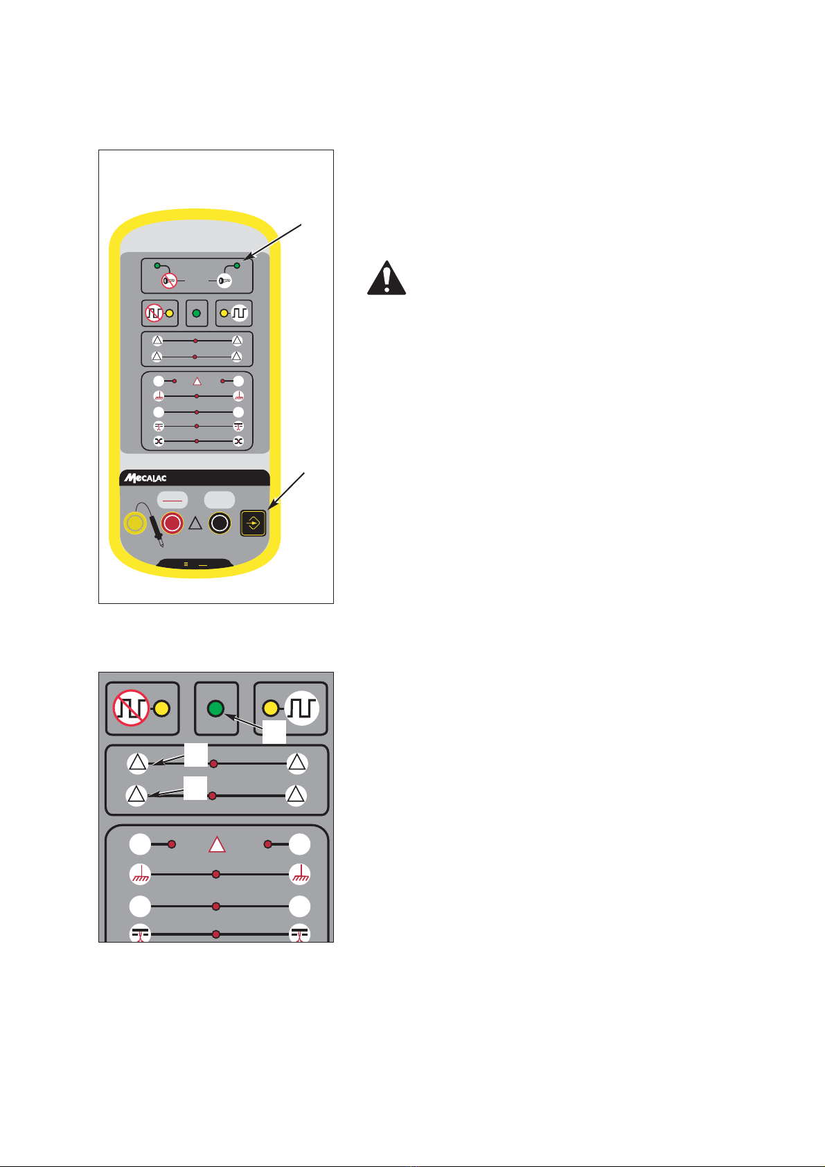
mecalac 714 PC User manual

xxo
xxo
test
test
!
CANH
CANH
DA
DA
TA
CANL
CANL
DA
DA
TA
CAN
++
CANH
CANH
CANL
CANL
!!
%%
OK
?
Ref K6956000
For complete inspection and diagnosis of CAN High Speed multiplex circuits
OPERATOR’S MANUAL

STATEMENT AND PRECAUTIONS TO BE READ BEFORE
USING THE R CVX200 MUXMETRE
To use the CVX200 in complete safety.
To prevent any damage to the CVX200.
• Operate the CVX299 only in accordance with the instructions in this
manual, so as to preserve its integrated protection.
• Do not operate the CVX200 if the tester or its leads are damaged,
or if the tester appears not to function correctly.
• Never apply a voltage higher than 36 V.
• Do not operate the tester near explosive gases, steam or dust.
• Observe all safety instructions regarding the machine which is
being tested.
714 PC & 714 PW

1
Page
Contents of the KIT ....................................................................
4
Tester connection........................................................................
5
Diagnostic procedure..................................................................
7
Static mode ................................................................................
8
Dynamic mode............................................................................
9
Identification of calculators present ..........................................
10
Interpretation of the indicator lights on the TX12......................
11
Table of Contents

714 PC & 714 PW
2
Contents of the KIT
A - Kit Part No. K6956000
B - Controller
C - Tester TX12
D - Interface cable Part No. 6956000
xxo
xxo
test
test
!
CANH
CANH
DA
DA
TA
CANL
CANL
DA
DA
TA
CAN
++
CANH
CANH
CANL
CANL
!!
%%
OK
?
Ref K6956000
xxo
xxo
test
test
B
A
C
D

714 PC & 714 PW
3
Connecting the tester
1-Connect the tester power supply clamps to the vehicle’s
battery terminals.(24V)
2-Connect the interface cable to the diagnostic soc-
ket on the vehicle (1 fig 1)
Kit K6956000
Fig. 1 Diagnostic socket (under the
seat)
1

4
714 PC & 714 PW
xxo
xxo
test
test
!
CANH
CANH
DA
DA
TA
CANL
CANL
DA
DA
TA
CAN
++
CANH
CANH
CANL
CANL
!!
%%
OK
?
Ref K6956000
Fig. 1 Tester
1
3
6
8
11
13
15
14
2
5
4
7
9
10
12
16
17

714 PC & 714 PW
5
Diagnostic procedure
Diagnosis
1This indicator lamp comes on if the tester is in static test mode (no voltage)
2This indicator lamp comes on if the tester is in dynamic test mode (voltage present)
3No communication (the wires 15 fig 1 and 16 fig 1 are not connected to a bus)
4The tester detects a signal which does not correspond to the selection or it is reversed in the socket
5Correct communication
6Non released fields are present
7The bus has too high a rate of load (one calculator is monopolising the bus)
8Locating a physical fault on CAN H
9Locating a physical fault on CAN L
10 Short circuit is “earthed”
11 Short circuit at the battery “positive”
12 Wire is cut
13 Short circuit between the lines
14 TX 12 tester connection socket (polarity tester)
15 Connection socket for the diagnostic cable
16 Connection socket for the diagnostic cable
17 Static test or dynamic test selector button

714 PC & 714 PW
6
Static mode
Purpose of test: check correct functioning of the CAN network
Machine not switched on
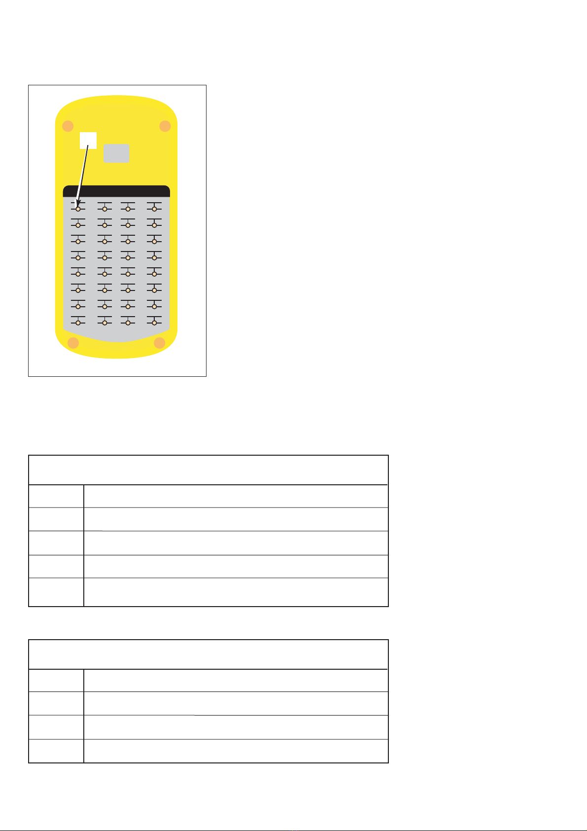
1-Put the device in static test mode by pressing successi-
vely on the button (1 fig 1) until the indicator lamp (2
fig 1) lights up.
Reaction of the device:
the CAN networks are equipped with 120 Ω terminal
resistances placed between the bus wires in the end
calculators of the network.
This check, apart from testing the line resistances, is
used to examine the physical condition of the bus (bus
cut through, short circuit wire, etc)
If the test is correct, the green LED (1 fig 2) on the
device will light up.
If a physical defect is found, indicator lamps cor-
responding to the physical errors will light up.
If one of the two wires is cut, the two LED’s on the
device will flash (2 fig 2).
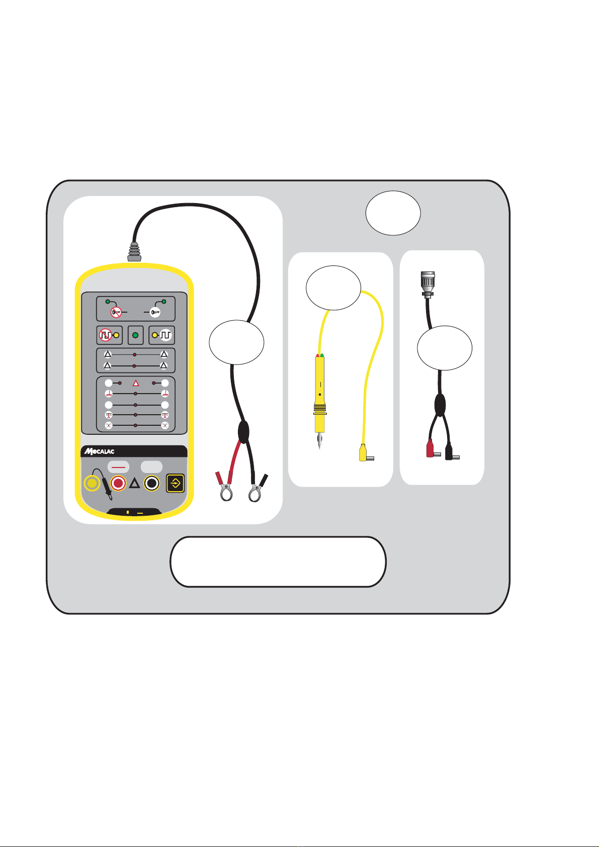
Fig. 1 Tester
xxo
xxo
test
test
!
CANH
CANH
DA
DA
TA
CANL
CANL
DA
DA
TA
CAN
++
CANH
CANH
CANL
CANL
!!
%%
OK
?
Ref K6956000
Fig. 2 Controller
xxo
test
!
CANH
DATA
CANL
DATA
++
CANHCANH CANLCANL
!!
%%
OK
?
1
2
"
1
2

714 PC & 714 PW
7
Dynamic mode
Machine switched on.
1-Put the tester in dynamic test mode by pressing repea-
tedly on the button (1 fig 1) until the indicator lamp
(2 fig 1) lights up.
Reaction of the device:
If no defect is found, the green LED (1 fig 2) on the
device will light up.
Possible errors:
Bus overload warning (2 fig 2).
one or more calculators are monopolising the net-
work communication.
Protocol errors (3 fig 2).
A field with an invalid format is detected on the net-
work. This field has not been released by the other
calculators present.
Causes can be as follows:
-One single calculator is present on the network.
-One or more calculators are operating with an
incorrect flow (problem of a clock outside tole-
rance, calculator not suitable for the network).
-Problem of unscheduled interference in the net-
work.
Fig. 1 Controller
Fig. 2 Controller
xxo
xxo
test
test
!
CANH
CANH
DA
DA
TA
CANL
CANL
DA
DA
TA
CAN
++
CANH
CANH
CANL
CANL
!!
%%
OK
?
Ref K6956000
xxo
test
!
CANH
DATA
CANL
DATA
++
CANH
CANH
CANL
CANL
!!
%%
OK
?
1
3
2
1
2

714 PC & 714 PW
8
MUXMETRE CVX200
CVX200
MECALAC
Sn 1001
CVX200
CVX200
MECALAC
MECALAC
Sn 1001
Sn 1001
00 20
01 21
02 22
03 23
04 24
05 25
06 26
07 27
08 28
09 29
0A 2A
0B 2B
0C 2C
0D 2D
0E 2E
0F 2F
10 30
11 31
12 32
13 33
14 34
15 35
16 36
17 37
18 38
19 39
1A 3A
1B 3B
1C 3C
1D 3D
1E 3E
1F 3F
Fig. 1 Controller
1
Identification of calculators present
Note: This is found using the indicator lamps
located on the back of the device
(example 1 fig1).
"
714 MW
Code Calculator
00 Engine calculator (under cab floor )
01 Instrument panel calculator (cab instrument panel screen)
02 Chassis calculator (under the chassis)
03 Upperstructure calculator (under cab floor )
714 MC
Code Calculator
00 Engine calculator (under cab floor )
01 Instrument panel calculator (cab instrument panel screen)
03 Upperstructure calculator (under cab floor )

714 PC & 714 PW
9
Interpretation of the indicator lights on the TX12
TX 12 tester
indicator lamps Interpretation of LED’s
GREEN The measurement is connected to the battery earth
Red The measurement is connected to the battery positive
GREEN and red (Pulses): Frequency control (injectors, multiplex bus)
Lamps extinguished No voltage, no positive, no earth: connection cut off
Special features:
It’s better than a multimeter ! The TX 12 tells you the difference between a point
connected to earth and a point “in the air” (not connected to earth or to the battery)
"

GROUPE MECALAC
MECALAC S.A.S. - Parc des Glaisins - 2, av. du Pré de Challes F-74940 Annecy-le-Vieux - France
Tel: +33 (0)4 50 64 01 63 - Fax : +33 (0)4 50 64 02 79
www.mecalac.com
This manual suits for next models
1
Table of contents
Other mecalac Excavator manuals