Meccanica Fadini VIX 53/1 R User manual

VIX 53/1 R (radio da esterno) - VIX 53/2 R (radio da innesto) - VIX 53/4 TR (trasmettitore). Frequenza 868,19 MHz
GENERALITÀ:
VIX 53/4 TR è un radio-trasmettitore a 4 tasti 868,19 MHz, Rolling code, bidirezionale (transceiver), ad autoapprendimento con
codica a 128 bit.
Il sistema radio si completa con la radio ricevente da innesto a 2 canali (Vix 53/2 R) e da esterno no a 4 canali
(Vix 53/1 R) (da abilitare con moduli relè da innesto). È possibile personalizzare gli impianti tramite lo strumento Red VIX 53. Con lo
strumento interfaccia mini-USB e Software dedicato (softVIXare 15.1) è possibile modicare e gestire i dati (memoria) delle radio
riceventi, anche a distanza. Qualora la ricevente non venga alimentata da programmatori della serie Elpro installare un fusibile di protezione
da 500 mA. Per un miglior funzionamento della ricevente si consiglia di collegare la massa dell’antenna alla massa dell’impianto.
Radio ricevente da esterno
Vix 53/1 R
VIX 53
Radio ricevente da innesto
Vix 53/2 R
DATI TECNICI
Radio da esterno (Vix 53/1 R) e da innesto (Vix 53/2 R)
Frequenza 868,19 MHz Rolling code
Alimentazione 12/24 Vace12/24 Vdc (Vix 53/1 R)
Alimentazione 24 Vac e 24 Vdc (Vix 53/2 R)
Assorbimento massimo 73 mA
Valore impedenza antenna 50 Ohm
Temperatura di funzion. -10 °C +55 °C
Portata contatto relè 0,5 A - 35 Vac o 1A-24 Vdc
Portata ricezione 250 m (*)
Massimo numero uscite 4 (Vix 53/1 R) e 2 (Vix 53/2 R)
N° telecomandi in memoria 2.000
Telecomando (Vix 53/4 TR)
Batteria 1 pila 3 V - CR2032
Durata stimata 2 anni
Codica Rolling code
Temperatura di funzion. -40 °C +85 °C
Dimensioni 65 x 36 x 12 mm
Peso 23 g
Codica 128 bit
Tecnologia transceiver
(*) in caso di maltempo, presenza di polveri o campo
di trasmissione ostacolato la distanza può diminuire
anche del 50%
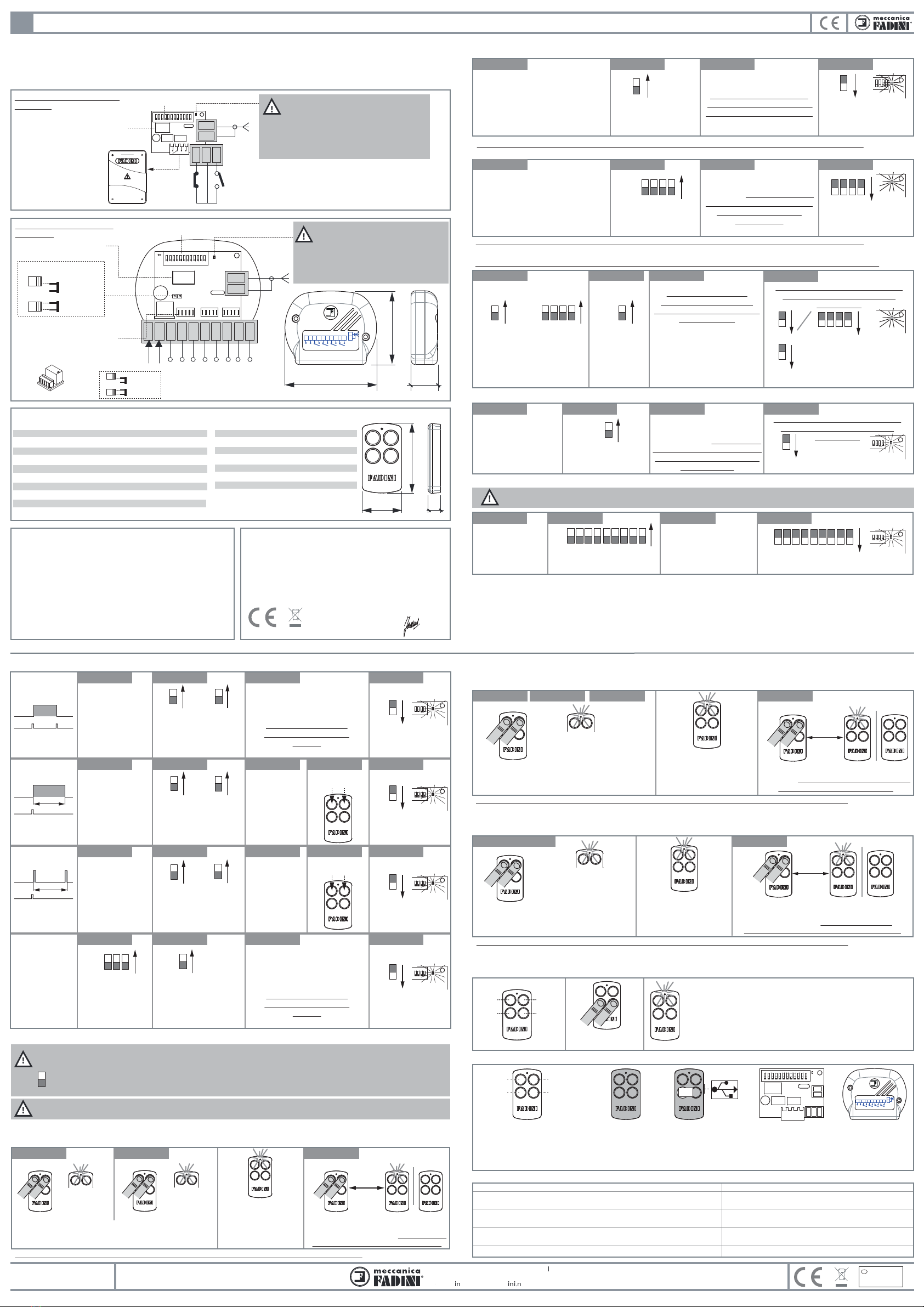
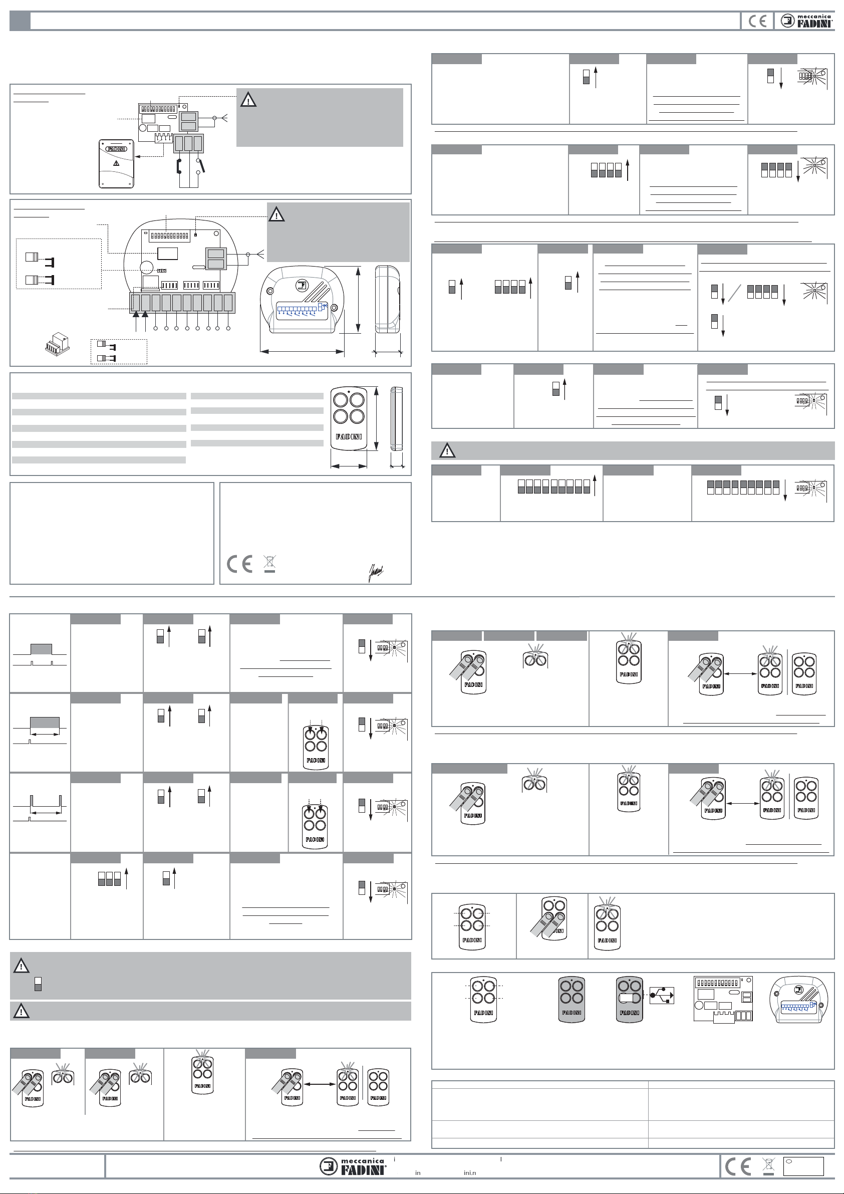
L’alimentazione e il 1°
canale radio NA vengono
abilitati inserendo la radio
nell’apposito connettore,
presente su tutti i
programmatori della serie
Elpro
2° canale radio:
morsetti 2-3 contatto NA
morsetti 1-2 contatto NC
NA
Comune
NC
Modulo Relè NA o NC: l’uscita
sui morsetti viene abilitata se
viene inserito il modulo nella
sua sede. Di serie viene fornito
un solo Relè NA
Memoria estraibile
per 2.000 telecomandi
Memoria estraibile
per 2.000 telecomandi
Dip-switch per la
programmazione
Dip-switch per la
programmazione
All’accensione della radio il LED rosso:
1 lampeggio = alimentazione presente
e radio senza chiave di protezione
5 lampeggi = indica la presenza della
chiave di protezione (impossibile
memorizzare telecomandi senza chiave)
All’accensione della radio il LED rosso:
1 lampeggio = alimentazione presente e
radio senza chiave di protezione
5 lampeggi = indica la presenza della
chiave di protezione (impossibile
memorizzare telecomandi senza chiave)
Relè1 Relè 2 Relè 3 Relè 4
VIX 53
1 2 3 4 5 6 7 8 9 10
GND
ANT
1 2 3
Selezionare il tipo
di alimentazione
12 Vac/dc
24 Vac/dc
Antenna
GND
ANT
GND
ANT
Antenna
1° canale
Relè 1
NA/NC
2° canale
Relè 2
NA/NC
3° canale
Relè 3
NA/NC
4° canale
Relè 4
NA/NC
1 2 3 4 5 6 7 8 9 10
12 Vac/dc
24 Vac/dc
-+
DIP-SWITCH
Dip 1 = relè 1: 1° canale
Dip 2 = relè 2: 2° canale
Dip 3 = relè 3: 3° canale
Dip 4 = relè 4: 4° canale
Dip 5 = Bistabile
Dip 6 = Timer 1
Dip 7 = Timer 2
DICHIARAZIONE DI CONFORMITÀ UE
Con la presente Meccanica Fadini snc dichiara che VIX 53 è conforme ai
requisiti essenziali ed alle altre disposizioni pertinenti stabilite dalle Direttive
2014/53/UE.
La dichiarazione di conformità può essere consultata sul sito: www.fadini.net
nella sezione prodotti.
Meccanica Fadini s.n.c.
Direttore Responsabile
36 mm
27
65
12
1.1 - MEMORIZZAZIONE DI 1 CANALE RADIO SU UNO O PIÙ TELECOMANDI (Vix 53/4 TR)
1.3 - MEMORIZZAZIONE MULTIPLA: INSERIRE CONTEMPORANEAMENTE 100 TELECOMANDI (Vix 53/4 TR) IN MEMORIA
1.2 - MEMORIZZAZIONE RAPIDA SU TUTTI E 4 I CANALI RADIO
Posizionare in ON il
Dip-switch corrispondente
al canale radio abilitato
Posizionare in ON il Dip-switch
corrispondente al canale radio
abilitato oppure tutti e 4 i
Dip-switch se devono essere
memorizzati tutti e 4 i tasti
(solo radio da esterno)
oppure
3 lampeggi di conferma
3 lampeggi di conferma
IMPORTANTE: questa operazione può essere eseguita solo ed esclusivamente su trasmettitori appositamente congurati in fabbrica in fase d’ordine.
ATTENZIONE: se non va a compimento l’operazione controllare se la chiave di protezione è presente sul telecomando e sulla radio ricevente.
ATTENZIONE: nel KIT vengono
identicati due telecomandi come
primo e ultimo di una serie di 100
telecomandi
RADIO DA INNESTO:
Innestare la radio sul programmatore
serie Elpro con l’antenna collegata.
RADIO DA ESTERNO:
Inserire il relè nella sede del canale radio
da abilitare, collegare l’antenna e
alimentare la radio.
ON
1 oppure 2, 3, 4
ON
1
ON
8
1
oppure 2, 3, 4
OFF
OFF 8
Radio ricevente alimentata con
antenna di ricezione collegata
Posizionare in ON i
Dip-switch n°1, 2, 3, 4
In prossimità della radio premere
un tasto qualsiasi del primo
telecomando, attendere che il
led si spenga, quindi premere un
tasto qualsiasi dell’ultimo
telecomando
Posizionare in
ON il
Dip-switch n° 8
In prossimità della radio premere
un tasto del telecomando
e attendere che si accenda e si
spenga il led sulla radio ricevente
prima di memorizzare altri
telecomandi
Attendere il lampeggio di conferma
memorizzazione prima di chiudere l’operazione
radio
ricevente
ON
123 4
ON
123 4 123 4
OFF
operazione 1
operazione 1
operazione 2
operazione 2
operazione 2
operazione 3
operazione 3
operazione 3
operazione 4
operazione 4
operazione 4
1 - RADIO RICEVENTE DA INNESTO (Vix 53/2 R) E DA ESTERNO (Vix 53/1 R)
I
RADIO DA INNESTO:
Innestare la radio sul programmatore
serie Elpro con l’antenna collegata.
RADIO DA ESTERNO:
Inserire il relè nella sede del canale radio
da abilitare, collegare l’antenna e
alimentare la radio.
operazione 1
In prossimità della radio premere
un tasto del telecomando da
memorizzare e attendere che si
accenda e si spenga il led sulla
radio ricevente prima di
memorizzare altri telecomandi
radio
ricevente
ATTENZIONE: se non va a compimento l’operazione controllare se la chiave di protezione è presente sul telecomando e sulla radio ricevente.
radio
ricevente
1.4 - CANCELLARE UN TELECOMANDO (Vix 53/4 TR) DALLA MEMORIA
In prossimità della radio premere
un tasto del telecomando
e attendere che si accenda e si
spenga il led sulla radio ricevente
prima di cancellare altri
telecomandi
Attendere il lampeggio di conferma
cancellazione prima di chiudere l’operazione
radio
ricevente
In prossimità della radio
premere un tasto qualsiasi
del telecomando
memorizzato e attendere
che il led si spenga
Posizionare in ON il
Dip-switch n° 9 3 lampeggi di conferma
ON
9
OFF 9
Radio ricevente
alimentata con
antenna di ricezione
collegata
1.5 - CANCELLARE TUTTA LA MEMORIA DELLA RADIO RICEVENTE DA INNESTO (Vix 53/2 R) E DA ESTERNO (Vix 53/1 R)
ATTENZIONE: questa operazione cancella denitivamente ogni telecomando memorizzato nella memoria
estraibile della radio ricevente
ON
1 2 3 4 5 6 7 8 9
Posizionare in ON tutti i
Dip-switch no al n° 9 3 lampeggi di conferma
Radio ricevente
alimentata con
antenna di ricezione
collegata
operazione 1
operazione 1
operazione 2
operazione 2
operazione 3
operazione 3
operazione 4
operazione 4
!
2 - FUNZIONE PONTE RADIO SU RADIO DA INNESTO (Vix 53/2 R) E DA ESTERNO (Vix 53/1 R)
Questa funzione permette di estendere la normale portata del telecomando VIX 53/4 TR creando un ponte radio con altre radio riceventi (da
innesto oppure da esterno) poste ad una distanza massima di 150 metri tra loro.
Per prima cosa è necessario memorizzare il/i telecomandi sulla radio ricevente terminale (da innesto oppure da esterno), secondo
procedura 1.1 oppure 1.2, poi installare quest’ultima come terminale del ponte.
Le riceventi del ponte, ad esclusione della radio ricevente terminale, eseguono la sola ricezione e la trasmissione del segnale, posizionando
il Dip-switch 10 in ON.
3 lampeggi di conferma
radio
ricevente
Posizionare in ON il
Dip-switch corrispondente
al canale radio sul quale
abilitare la funzione
ON
1
oppure 2, 3, 4
ON
1
oppure 2, 3, 4
ON
1
oppure 2, 3, 4
ON
1 oppure 2, 3, 4
3 lampeggi di conferma
funzione passo-passo
Ripristino del
funzionamento
normale del canale
memorizzato
OFF
ON
567
3.1 - Bistabile
+
+
operazione 1 operazione 2 operazione 3 operazione 4
operazione 1 operazione 2 operazione 3 operazione 5operazione 4
operazione 1 operazione 2 operazione 3 operazione 5operazione 4
operazione 1 operazione 2 operazione 3 operazione 4
3 - FUNZIONI AGGIUNTIVE SULLA RADIO da esterno (Vix 53/1 R) e da innesto (Vix 53/2 R)
Memorizzare un tasto
del telecomando
su un canale radio
(vedi 1.1 o 1.2
memorizzazione
sulla radio) sul quale
poi abilitare questa
funzione
Memorizzare un tasto
del telecomando
su un canale radio
(vedi 1.1 o 1.2
memorizzazione
sulla radio) sul quale
poi abilitare questa
funzione
Memorizzare un tasto
del telecomando
su un canale radio
(vedi 1.1 o 1.2
memorizzazione
sulla radio) sul quale
poi abilitare questa
funzione
ON
5
out
input
Posizionare in ON il
Dip-switch corrispondente
al canale radio sul quale
abilitare la funzione
In prossimità
della radio
premere un
tasto qualsiasi
del telecomando
per azzerare
i tempi
3.2 - Timer 1
3.3 - Timer 2
3.4 - Cancellare le
funzioni aggiuntive
ON
6
Posizionare in ON il
Dip-switch corrispondente
al canale radio sul quale
abilitare la funzione
Posizionare in ON il
Dip-switch corrispondente
al canale radio con la
funzione aggiuntiva
attivata
Posizionare in ON i
Dip-switch 5, 6, 7
ON
7
out
input
T
out
input
T
minuti
max 60
secondi
max 60
In prossimità
della radio
premere un
tasto qualsiasi
del telecomando
per azzerare
i tempi
In prossimità della radio
premere un tasto del
telecomando e attendere
che si accenda e si spenga il
led sulla radio ricevente
In prossimità della radio
premere un tasto del
telecomando
e attendere che si accenda e
si spenga il led sulla radio
ricevente
ATTENZIONE: se non va a compimento l’operazione controllare se la chiave di protezione è presente sul telecomando e sulla radio ricevente.
Per 2 volte eseguire questa operazione: premere e rilasciare
contemporaneamente i primi due tasti del telecomando: il led
emetterà 2 lampeggi la prima volta e 3 lampeggi la seconda
Premere contemporaneamente i primi
due tasti del telecomando già memorizzato
no a quando il led del telecomando
nuovo lampeggia e si spegne
4 - TELECOMANDO (Vix 53/4 TR)
20 cm
4.1 - DUPLICAZIONE DEL TELECOMANDO (Vix 53/4 TR)
Questa procedura permette di inserire un nuovo telecomando nella radio ricevente avendo a disposizione un telecomando già
memorizzato. I due telecomandi devono essere posti ad una distanza di 20 cm circa.
operazione 2 operazione 3operazione 1
impulso tenere premuto
memorizzato
3 lampeggi
nuovo
nuovo
nuovo
Il led del telecomando
nuovo rimane acceso per
4 secondi circa: tempo
utile per concludere la
procedura
Dip 11= ON la radio non accetta telecomandi duplicati tra loro, a distanza dall’impianto, anche con software su PC
Dip 11= OFF la radio accetta telecomandi duplicati tra loro, a distanza dall’impianto, anche con software su PC
11
!
IMPORTANTE: la radio ricevente viene fornita in modalità per poter duplicare a distanza i telecomandi (anche con software
su PC) senza dover intervenire sulla radio stessa. Tuttavia, è facoltà dell’installatore non consentire questa funzione
posizionando il Dip-switch 11 in ON:
!
IMPORTANTE: Tutte le operazioni 4.1, 4.2, 4.3 eseguite sul telecomando, possono essere eettuate a distanza
dall’impianto senza quindi intervenire sicamente in alcun modo sulla radio ricevente.
ATTENZIONE: se non va a compimento l’operazione controllare se la chiave di protezione è presente sul telecomando e sulla radio ricevente.
ATTENZIONE: se non va a compimento l’operazione controllare se la chiave di protezione è presente sul telecomando e sulla radio ricevente.
4.2 - SOSTITUZIONE DEL TELECOMANDO (Vix 53/4 TR)
Questa procedura permette di sostituire un telecomando già memorizzato nella radio ricevente con un nuovo telecomando.
I due telecomandi devono essere posti ad una distanza di 20 cm circa.
4.3 - CANCELLAZIONE DEL TELECOMANDO (Vix 53/4 TR)
Questa procedura permette di cancellare un telecomando memorizzato nella radio ricevente tramite un nuovo telecomando o uno
memorizzato nella radio. I due telecomandi devono essere posti ad una distanza di 20 cm circa.
impulso
da cancellare
LED acceso per
4 secondi circa: tempo
utile per concludere la
procedura
Per 4 volte eseguire la 1a operazione: premere e
rilasciare contemporaneamente i primi due tasti del
telecomando memorizzato/nuovo
Premere contemporaneamente i primi due tasti del
telecomando da cancellare no a quando il led del
telecomando memorizzato/nuovo lampeggia e si spegne
operazione 5
operazione 1 - 2 - 3 - 4
2 lampeggi la 1avolta
3 lampeggi la 2avolta
4 lampeggi la 3avolta
5 lampeggi la 4a volta
memorizzato/nuovo
memorizzato/nuovo memorizzato/nuovo
Premere contemporaneamente i primi due tasti del
telecomando già memorizzato no a quando il led
del telecomando nuovo lampeggia e si spegne
impulso tenere premuto
nuovo
Per 3 volte eseguire questa operazione:
premere e rilasciare contemporaneamente i primi
due tasti del telecomando
operazione 4operazione 3operazione 1 operazione 2
2 lampeggi la 1avolta
3 lampeggi la 2avolta
4 lampeggi la 3avolta
nuovo
nuovo
LED acceso per
4 secondi circa: tempo
utile per concludere la
procedura
4.4 - VERIFICARE LA PRESENZA DELLA CHIAVE DI PROTEZIONE SUL TELECOMANDO (Vix 53/4 TR)
Premere contemporaneamente il 3° e 4° tasto per 2-3 secondi: se il led emette 3 lampeggi il telecomando è stato personalizzato con
una chiave di protezione. Se invece il led rimane spento non c’è nessuna chiave di protezione.
INTERVENTI PER UN CORRETTO FUNZIONAMENTO
FAMIGLIA DEL RADIO-TRASMETTITORE (Vix 53/4 TR)
1
3
2
4
tenere premuto
per 2-3 secondi
3 lampeggi = chiave di protezione inserita
Telecomando a 4 pulsanti
VIX 53/4 TR con cover nei
colori: verde lime,
giallo mustard,
lilla candy
Strumento RED VIX 53
di colore rosso
per inserire/togliere la
chiave di protezione
Interfaccia
softVIXare 53
di colore rosso
Radio da innesto
VIX 53/2 R
Radio da esterno
VIX 53/1 R
nessun lampeggio = nessuna chiave di protezione inserita
Anomalia
Le procedure dei capitoli 1, 2, 3 e 4 sulla radio e sul telecomando
non vanno a buon ne.
Telecomando ha poca portata.
A distanza dall’impianto, premendo un tasto del telecomando,
lampeggia il led invece di essere sso per qualche secondo.
Non funzionano le procedure al capitolo 4 sul telecomando.
Procedura di intervento
- Controllare se è presente la chiave nella radio e nel telecomando
- Controllare la posizione ed i collegamenti dell’antenna
- Sostituire la batteria sul telecomando
- Pila quasi scarica, da sostituire
- Controllare la posizione del Dip 11
VIX 53
1 2 3
GND
ANT
3
12
4
VIX 53
Dip 8 = memorizza 100 telecomandi
Dip 9 = cancellare 1 telecomando
Dip 10 = funzione ponte radio
Dip 11 = duplicazione telecomandi
anche a distanza con PC
Dip 12 = libero
1
OFF
OFF 1 2 3 4 5 6 7 8 9
3 lampeggi di conferma
OFF
3 lampeggi di conferma
OFF
3 lampeggi di conferma
OFF
OFF 123 4
20 cm
20 cm
+
impulso
2 lampeggi
nuovo
!
!
minuti
max 60
secondi
max 60
Dis. N. 7771
VIE
T
A
T
T
T
A
A
O
G
E
T
T
ARE NEI RIFIUTI
T
T
M
A
TERIALI NOCIVI PER
A
A
L
’
LL
AMBIENTE
’
I
D
i
r
ett
i
v
a 2012
/
19
/U
E
S
m
a
l
t
i
m
e
n
t
o dei
m
a
t
e
r
i
al
i
e
l
e
t
t
r
ic
i
e
d
e
l
e
t
t
r
o
ni
c
i
+-
20210503
91 mm
73
VIX 53/1 R
VIX 53/1 R
12-24V
cc/ca R1 R2 R3 R4
+
-
12
345678910
12-24V
cc/ ca R1 R2 R3 R4
+
-
12
3456 78910
V
i
a
M
a
n
t
o
v
a
, 177
/
A -
3
7
0
5
3
C
e
r
e
a
(
V
R
)
I
t
al
y
Ph
.
+
39
0
44
2
330
4
22
-
F
a
x +
39
0
44
2
33
1
05
4
i
n
f
o
f
f
@
fa
d
i
n
i.
n
et
-
w
w
w
.f
a
d
i
n
i
.
n
e
t

GENERAL DESCRIPTION: VIX 53/4 TR is a radio-transmitter with 4 buttons, 868,19 MHz, Rolling code, bidirectional (transceiver),
auto-learning, 128 bit encoding. This receiver system includes two receiver options, either plug-in with two channels (Vix 53/2 R) or up to
4 channels (Vix 53/1 R stand alone) (enabled by plug-in modules). It is possible to customized any installation by the Red VIX 53 device.
By means of a mini-USB interface and a dedicated software (softVIXare 15.1) it is possible to change and manage the data (memory) of
the radio receivers, even from a distance. Fit a 500 mA fuse as a protection should the controller not be Elpro type. To get a better
functioning of the receiver, it is recommended that the aerial ground terminal is connected to the ground terminal of the installation.
VIX 53
Plug-in radio receiver
Vix 53/2 R
TECHNICAL DATA
Stand alone Vix 53/1 R / plug-in Vix 53/2 R receivers
Frequency 868,19 MHz Rolling code
Power supply 12/24Vac&12/24 Vdc (Vix 53/1 R)
Power supply 24 Vac & 24 Vdc (Vix 53/2 R)
Max absorption 73 mA
Aerial impedance 50 Ohm
Working temperature -10 °C +55 °C
Relay contact rating 0,5 A - 35 Vac or 1A-24 Vdc
Distance range 250 m (*)
No. of outputs max. 4 (Vix 53/1 R) & 2 (Vix 53/2 R)
Transmitters in the memory
2.000
(Vix 53/4 TR) transmitter
Battery 1 x 3 V - CR2032
Estimated battery life 2 years
Encoding system Rolling code
Working temperature -40 °C +85 °C
Dimensions 65 x 36 x 12 mm
Weight 23 g
Encoding 128 bit
Technology transceiver
(*) in bad weather or in case of dusts or obstructed
transmission eld, distance can be reduced by 50%
Power supply and NO
receiver channel 1 are
enabled by inserting the
receiver into the dedicated
connector, tted onto all
the Elpro controllers
Receiver channel 2:
terminals 2-3 - NO contact
terminals 1-2 - NC contact
NO
common
NC
Removable memory
for 2.000 remote controls
Programming
Dip-switches
Programming
Dip-switches
On powering the radio receiver, the red LED:
1 Flash = voltage supplied and receiver
has no protection key code
5 Flashes = protection key code
activated (impossible to memorize
remote controls in it without key code)
On powering the radio receiver, the red LED:
1 Flash = voltage supplied and receiver has no
protection key code
5 Flashes = protection key code activated
(impossible to store remote controls in it without
key code)
Relay 1
Relay 2 Relay 3 Relay 4
VIX 53
1 2 3 4 5 6 7 8 9 10
GND
ANT
1 2 3
Aerial
GND
ANT
GND
ANT
Aerial
Channel 1
Relay 1
NO/NC
Channel 2
Relay 2
NO/NC
Channel 3
Relay 3
NO/NC
Channel 4
Relay 4
NO/NC
1 2 3 4 5 6 7 8 9 10
12 Vac/dc
24 Vac/dc
-+
DIP-SWITCH
Dip 1 = relay 1: channel 1
Dip 2 = relay 2: channel 2
Dip 3 = relay 3: channel 3
Dip 4 = relay 4: channel 4
Dip 5 = Bistable
Dip 6 = Timer 1
Dip 7 = Timer 2
UE DECLARATION OF CONFORMITY (DoC)
Hereby Meccanica Fadini snc declares that VIX 53 is in compliance with
the essential requirements and other relevant provisions of Directive
2014/53/UE. The declaration of conformity can be viewed on this website:
www.fadini.net in the product section.
Meccanica Fadini s.n.c.
Managing director
65
1.1 - MEMORIZING 1 RECEIVER CHANNEL ON ONE OR MORE REMOTE CONTROLS (Vix 53/4 TR)
1.3 - MULTI-MEMORY: 100 REMOTE CONTROLS (Vix 53/4TR) ARE MEMORIZED AT ONE TIME
1.2 - FAST MEMORY ON ALL 4 CHANNELS OF THE RADIO RECEIVER
Position to ON the
Dip-switch corresponding to
the enabled receiver channel
Position to ON the Dip-switch
corresponding to the enabled
receiver channel or all 4
Dip-switches if all 4 buttons are
required to be memorized
(only with stand alone receivers)
or
3 conrming ashes
3 conrming ashes
IMPORTANT: This operation can be exclusively performed on transmitters factory pre-set for it on demand at the time of the order.
NOTE WELL: if no result is achieved, check if the protection key code is set in the remote control and radio receiver.
NOTE WELL: in the KIT are
identied two transmitters as
rst and last in a batch of 100
transmitters
PLUG-IN RADIO RECEIVER:
Fit the receiver card into the connector in
the Elpro controller, aerial connected.
STAND ALONE RADIO RECEIVER
Fit the relay module on to the dedicated
seat corresponding to the required channel,
connect the aerial and supply with power.
ON
1 or 2, 3, 4
ON
1
ON
8
1
or 2, 3, 4
OFF
OFF 8
Radio receiver power supplied
and aerial connected
Position to ON
Dip-switches 1, 2, 3, 4
In proximity of the radio receiver
press any one button of the rst
transmitter, wait for the led to go
o, then press any one button of
the last transmitter
Position to ON
Dip-switch 8
In proximity of the radio receiver
press the transmitter button
and wait for the LED to go on
and o in the radio receiver
before memorizing other
transmitters
Wait for the ashes conrming memorizing
achieved before stopping the operation
radio
receiver
ON
123 4
ON
123 4 123 4
OFF
operation 1
operation 1
operation 2
operation 2
operation 2
operation 3
operation 3
operation 3
operation 4
operation 4
operation 4
1 - PLUG-IN RADIO RECEIVER (Vix 53/2 R) and STAND ALONEVix 53/1 R
GB
PLUG-IN RADIO RECEIVER:
Fit the receiver card into the connector in
the Elpro controller, aerial connected.
STAND ALONE RADIO RECEIVER
Fit the relay module on to the dedicated
seat corresponding to the required channel,
connect the aerial and supply with power.
operation 1
In proximity of the radio receiver
press a button of the transmitter
to memorize and wait for the
LED to go on and o in the radio
receiver before memorizing
other transmitters
radio
receiver
NOTE WELL: if no result is achieved, check if the protection key code is set in the remote control and radio receiver.
radio
receiver
1.4 - DELETING A REMOTE CONTROL (Vix 53/4 TR) FROMTHE MEMORY
In proximity of the radio receiver
press a transmitter button and
wait for the LED to go on and o
in the radio receiver before
deleting other transmitters
Wait for the ashes conrming deletion
achieved before stopping the operation
radio
receiver
In proximity of the receiver
press any one button of the
memorized transmitter and
wait for the LED to go o
Position to ON
Dip-switch 93 conrming ashes
ON
9
OFF 9
Radio receiver power
supplied and aerial
connected
1.5 - DELETING THE ENTIRE MEMORY OFTHE plug-in (Vix 53/2 R) and stand alone (Vix 53/1 R) RADIO RECEIVERS
NOTE WELL: this operation cancels denitively any transmitter memorized in the removable memory of the
radio receiver.
ON
1 2 3 4 5 6 7 8 9
Position to ON all
Dip-switches up to 93 conrming ashes
Radio receiver power
supplied and aerial
connected
operation 1
operation 1
operation 2
operation 2
operation 3
operation 3
operation 4
operation 4
!
2 - RADIO LINK FUNCTION WITH plug-in (Vix 53/2 R) and stand alone (Vix 53/1 R) RADIO RECEIVERS
This function increases the standard distance range of the VIX 53/4TR transmitter creating a radio link with other radio receivers (plug-in or
stand alone) that are positioned at a maximum distance of 150 meters from one another.
As rst step memorize the transmitter/s in the terminal radio receiver (plug-in or stand alone), following operation 1.1 or 1.2, then install
this one in the terminal position of the sequence (radio link).
The receivers in the link, with the exclusion of the terminal one, can only receive and further transmit the signal by setting Dip-Switch 10
to ON.
3 conrming ashes
radio
receiver
ON
1
or 2, 3, 4
ON
1
or 2, 3, 4
ON
1
or 2, 3, 4
ON
1 or 2, 3, 4
3 conrming ashes
step-by-step function
Resetting the
enabled channel
back to normal
operating mode
OFF
ON
567
3.1 - Bistable
+
+
operation 1 operation 2 operation 3 operation 4
operation 1 operation 2 operation 3 operation 5operation 4
operation 1 operation 2 operation 3 operation 5operation 4
operation 1 operation 2 operation 3 operation 4
3 - ADDITIONAL FUNCTIONS PERFORMED BY THE RADIO RECEIVER (Vix 53/1 R stand alone) and plug-in (Vix 53/2 R)
Memorize a
transmitter button on
a receiver channel
(see 1.1 or 1.2 radio
receiver memorizing)
on which this
function is required
to be enabled
Memorize a
transmitter button on
a receiver channel
(see 1.1 or 1.2 radio
receiver memorizing)
on which this
function is required
to be enabled
Memorize a
transmitter button on
a receiver channel
(see 1.1 or 1.2 radio
receiver memorizing)
on which this
function is required
to be enabled
ON
5
output
input
Position to ON the
Dip-switch corresponding
to the receiver channel
enabled to this function
In proximity of
the radio
receiver press a
button of the
transmitter to
set times to zero
3.2 - Timer 1
3.3 - Timer 2
3.4 - Deleting
the additional
functions
ON
6
Position to ON the
Dip-switch corresponding
to the receiver channel
enabled to this function
Position to ON the
Dip-switch corresponding
to the receiver channel
enabled to the additional
function
Position to ON
Dip-switches 5, 6, 7
ON
7
output
input
T
output
input
T
minutes
max 60
seconds
max 60
In proximity of
the radio
receiver press a
button of the
transmitter to
set times to zero
In proximity of the radio receiver
press a button of the transmitter
and wait for the LED to go
on and o in the radio receiver
In proximity of the radio receiver
press a button of the transmitter
and wait for the LED to go on
and o in the radio receiver
NOTE WELL: if no result is achieved, check if the protection key code is set in the remote control and radio receiver.
Perform this operation for two times: press and release
the rst two buttons of the transmitter at the same
time: the LED will give out 2 ashes the rst time and 3
ashes the second time
Press at the same time the rst two buttons
of the transmitter, already memorized,
until the led of the NEW transmitter
ashes and then goes o
4 - (Vix 53/4 TR) TRANSMITTER
20 cm
4.1 - (Vix 53/4 TR) TRANSMITTER DUPLICATION
This operation allows for a new transmitter to be memorized in the radio receiver when a previously memorized transmitter is available.
The two transmitters must be at a distance of about 20 cm from each other.
operation 2 operation 3operation 1
pulse hold on pressed
memorized
3 ashes
new
new
new
The LED of the NEW
transmitter stays alight for
about 4 seconds: during
this time the operation
must be terminated
Dip 11= ON the receiver does not accept transmitters inter-duplicated from a distance or by PC and software
Dip 11= OFF the receiver accepts transmitters inter-duplicated from a distance or by PC and software
11
!
IMPORTANT: The radio receiver comes in remote duplication mode, that is the possibility of duplicating the transmitters
from a distance (even by PC through a dedicated software) without any action on the receiver.
Nevertheless the installer can decide to disable this function by setting Dip-switch 11 to ON:
!
NOTE WELL: all operations 4.1, 4.2, 4.3 performed on the transmitter, can be carried on at a distance from the installation
without any phisical action on the radio receiver.
NOTE WELL: if no result is achieved, check if the protection key code is set in the remote control and radio receiver.
NOTE WELL: if no result is achieved, check if the protection key code is set in the remote control and radio receiver.
4.2 - (Vix 53/4 TR) TRANSMITTER REPLACING
This operation allows for a transmitter, previously memorized in the radio receiver, to be replaced with a new transmitter.
The two transmitters must be at a distance of about 20 cm from each other.
4.3 - (Vix 53/4 TR) TRANSMITTER DELETING
This operation allows for a transmitter, previously memorized in the radio receiver, to be deleted by a new transmitter or by one
memorized in the radio receiver. The two transmitters must be at a distance of about 20 cm.
pulse
20 cm
to delete
The LED stays alight for
about 4 seconds:
operation to terminate
within this time
Perform the 1st operation for 4 times: press and
release at the same time the rst two buttons of
the transmitter already memorized/new
Press at the same time the rst two buttons of the
transmitter to delete until the led of the already
memorized/new transmitter ashes and goes o
operation 5
operations 1 - 2 - 3 - 4
2 ashes 1st time
3 ashes 2nd time
4 ashes 3rd time
5 ashes 4th time
memorized/new
memorized/new memorized/new
Press at the same time the rst two buttons of
the already memorized transmitter
until the led of the NEW transmitter ashes
and then goes o
pulse hold on pressed
new
Perform this operation for 3 times: press
and release the rst two buttons of the
transmitter at the same time
operation 4operation 3operation 1 operation 2
2 ashes 1st time
3 ashes 2nd time
4 ashes 3rd time
new
new
The LED of the NEW
transmitter stays alight for
about 4 seconds: operation
to terminate within this time
4.4 - CHECKING IF A (Vix 53/4 TR) TRANSMITTER IS PROTECTED BY A KEY CODE
Press buttons 3and 4at one time for 2-3 seconds: if the LED emits 3 ashes the remote control is mastered by a protection key code. No
ashing, no protection code.
TROUBLE SHOOTING
ALSO IN THE FAMILY OF THE (Vix 53/4 TR) TRANSMITTER AND RECEIVERS
1
3
2
4
hold on pressed
for 2-3 seconds
3 ashes = protection key code inserted
4-channel transmitter
VIX 53/4 TR
cover in the following colours:
lime-green, mustard yellow,
candy lilac
RED VIX 53
instrument for
inserting/deleting the
protection key code
SoftVIXare 53
interface
red in colour
VIX 53/2 R
plug-in radio receiver
VIX 53/1 R
stand alone
radio receiver
no ashing = no protection key code inserted
Trouble
Operations in sections 1, 2, 3 and 4 with the receiver and transmitter fail,
no functioning
Short distance range
At a distance from the installation, by pressing any button of the remote
control, the LED ashes instead of being xed for a few seconds
Operations on the transmitter as described in section 4 are not working
How to cure it
- Make sure that both the receiver and transmitter
are key-encoded
- Check the aerial position and connections
- Replace battery in the transmitter
- Battery almost run out, replace
- Check position of Dip 11
VIX 53
1 2 3
GND
ANT
3
12
4
VIX 53
Dip 8 = can memorize 100 transmitters
Dip 9 = can delete 1 transmitter
Dip 10 = receiver link function
Dip 11 = can duplicate transmitters
even from a distance by PC
Dip 12 = blank
1
OFF
OFF 1 2 3 4 5 6 7 8 9
minutes
max 60
seconds
max 60
3 conrming ashes
OFF
3 conrming ashes
OFF
3 conrming ashes
OFF
OFF 123 4
20 cm
+
pulse
2 ashes
new
!
!
Position to ON the
Dip-switch corresponding
to the receiver channel
enabled to this function
GB 2012
/
19
/U
E
D
ir
ect
iv
e
Disposal of electric and
e
l
ect
r
o
ni
c
m
ate
ri
a
l
s
DISP
O
SE PR
O
PERLY
O
F MATERIAL
S
HARMF
U
L T
O
ENVIR
O
NMEN
T
Drwg. No. 7771
+-
VIX 53/1 R (stand alone) - VIX 53/2 R (plug-in) - VIX 53/4 TR (transmitter). 868,19 MHz frequency
VIX 53/1 R
12-24V
cc/ca R1 R2 R3 R4
+
-
12
345678910
27
91 mm
73
VIX 53/1 R
12-24V
cc/ ca R1 R2 R3 R4
+
-
12
3456 78910
36 mm 12
Stand alone radio receiver
Vix 53/1 R
NO or NC relay module:
The terminal output is enabled
provided that the relay module
is tted in its seat.
Standard with 1 NO relay only
Removable memory
for 2.000 remote controls
Power supply
selection
12 Vac/dc
24 Vac/dc
V
i
a
M
a
n
t
o
v
a
, 177
/
A -
3
7
0
5
3
C
e
r
e
a
(
V
R
)
I
t
al
y
Ph
.
+
39
0
44
2
330
4
22
-
F
a
x +
39
0
44
2
33
1
05
4
i
n
f
o
f
f
@
fa
d
i
n
i.
n
et
-
w
w
w
.f
a
d
i
n
i
.
n
e
t
20210503
VIX 53/1 R (récepteur radio en saillie) - VIX 53/2 R (récepteur radio enchable) - VIX 53/4 TR (émetteur). Fréquence 868,19 MHz
VIX 53
Récepteur radio enchable
Vix 53/2R
DONNEES TECHNIQUES
Récepteur radio en saillie (Vix 53/1 R) et enchable (Vix 53/2 R)
Fréquence 868,19 MHz Rolling code
Alimentation
12/24 Vac et 12/24 Vdc (Vix 53/1 R)
Alimentation 24 Vac et 24 Vdc (Vix 53/2R)
Absorption maximale 73 mA
Impédance d'antenne 50 Ohm
Température de fonction. -10 °C +55 °C
Plage de distance contact relais 0,5 A - 35 Vac ou 1A-24 Vdc
Plage de distance 250 m (*)
Nr. sorties max. 4 (Vix 53/1) et 2 (Vix 53/2R)
Nr. télécommandes mémorisées 2.000
Télécommande (Vix 53/4TR)
Batterie 1 x 3 V - CR2032
Autonomie estimée 2 ans
Système de codage Rolling code
Température de fonction. -40 °C +85 °C
Dimensions 65 x 36 x 12 mm
Poids 23 g
Codage 128 bit
Technologie transceiver
(*) La distance peut diminuer même jusqu'à 50% en
présence de brouillard, pluie ou poudres.
L'alimentation et le premier
canal radio NO sont activés en
enchant le récepteur radio
dans le connecteur approprié
qui se trouve sur tous les
programmateurs de la série
Elpro.
2ème canal radio:
bornes 2-3 contact NO
bornes 1-2 contact NF
NO
Commun
NF
Mémoire amovible
pour 2.000 télécommandes
Dip-switch pour la
programmation
Dip-switch pour la
programmation
A la mise sous tension du récepteur
radio, la Led rouge:
1 clignotement = tension présente et
récepteur radio sans code de protection.
5 clignotements = présence du code de
protection (impossible mémoriser des
nouvelles télécommandes sans ce code).
A la mise sous tension du récepteur radio, la
Led rouge:
1 clignotement = tension présente et
récepteur radio sans code de protection
5 clignotements = présence du code de
protection (impossible mémoriser des
nouvelles télécommandes sans ce code).
Relais1 Relais 2 Relais 3 Relais 4
VIX 53
1 2 3 4 5 6 7 8 9 10
GND
ANT
1 2 3
Antenne
GND
ANT
GND
ANT
Antenne
Canal 1
Relais 1
NO/NF
Canal 2
Relais 2
NO/NF
Canal 3
Relais 3
NO/NF
Canal 4
Relais 4
NO/NF
1 2 3 4 5 6 7 8 9 10
12 Vac/dc
24 Vac/dc
-+
DIP-SWITCH
Dip 1 = relais 1: canal 1
Dip 2 = relais 2: canal 2
Dip 3 = relais 3: canal 3
Dip 4 = relais 4: canal 4
Dip 5 = Bistable
Dip 6 = Timer 1
Dip 7 = Timer 2
DECLARATION DE CONFORMITE UE
Par la présente Meccanica Fadini snc déclare que la télécommande
VIX 53 est conforme aux exigences essentielles et aux autres dispositions
pertinentes de la Directive 2014/53/UE.
La déclaration de conformité peut être consultée sur le site:
www.fadini.net dans la section produits.
Meccanica Fadini s.n.c.
Directeur général
65
1.1 - MEMORISATION D'UN CANAL RADIO SUR UNE OU PLUS TELECOMMANDES (Vix 53/4 TR)
1.3 MEMORISATION MULTIPLE : MEMORISEZ SIMULTANEMENT 100 TELECOMMANDES VIX 53/4 TR
1.2 - MEMORISATION RAPIDE DE TOUS LES 4 CANAUX RADIO
Positionnez le Dip-switch
correspondant au canal
radio activé sur ON
Positionnez sur ON le Dip-switch
correspondant au canal radio
activé ou tous les 4 Dip-switch, si
on doit mémoriser tous les 4
boutons (seulement récepteur
radio en saille)
ou
3 clignotements pour
conrmation
3 clignotements pour conrmation
ATTENTION : cette opération peut être eectuée exclusivement sur des télécommandes spécialement congurées en usine lors de la commande.
ATTENTION: si l'opération ne réussit pas, vériez la présence d'un code de protection dans le récepteur radio et la télécommande
ATTENTION: dans le KIT on
identie deux télécommandes
comme la première et la dernière
d'une série de 100.
RECEPTEUR RADIO ENFICHABLE :
Enchez le récepteur radio sur le
programmateur Elpro avec l’antenne
connectée.
RECEPTEUR RADIO EN SAILLIE :
Enchez le relais dans le connecteur du
canal radio à actionner, branchez
l’antenne et alimentez le récepteur radio.
ON
1 ou 2, 3, 4
ON
1
ON
8
1
ou 2, 3, 4
OFF
OFF 8
Récepteur radio alimenté avec
l’antenne branchée
Positionnez les
Dip-switch 1,2,3,4 sur
ON
Positionnez sur
ON le
Dip-switch 8
Près du récepteur radio appuyez un
bouton de la télécommande et
attendez que la Led du récepteur
radio s'allume et s’éteigne avant de
mémoriser d'autres télécommandes
Terminez l'opération seulement après le
clignotement de conrmation de la
mémorisation
récepteur
radio
ON
123 4
ON
123 4 123 4
OFF
opération 1
opération 1
opération 2
opération 2
opération 2
opération 3
opération 3
opération 3
opération 4
opération 4
opération 4
1 - RECEPTEUR RADIO ENFICHABLE Vix 53/2 R ET Vix 53/1 R RECEPTEUR RADIO EN SAILLIE
F
RECEPTEUR RADIO ENFICHABLE:
Enchez le récepteur radio sur le
programmateur Elpro avec l’antenne
connectée.
RECEPTEUR RADIO EN SAILLIE:
Enchez le relais dans le connecteur du canal
radio à actionner, branchez l’antenne et
alimentez le récepteur.
opération 1
Près du récepteur radio appuyez sur
le bouton de la télécommande à
mémoriser et attendez que la Led du
récepteur radio s'allume et s’éteigne
avant de mémoriser d'autres
télécommandes
récepteur
radio
ATTENTION: si l'opération ne réussit pas, vériez la présence d'un code de protection dans le récepteur radio et la télécommande.
récepteur
radio
1.4 - EFFACEMENT D’UNE TELECOMMANDE (Vix 53/4TR) DE LA MEMOIRE
Près du récepteur radio, appuyez
sur un bouton de la
télécommande et attendez que la
Led du récepteur radio s'allume et
s'éteigne avant d’éacer d’autres
télécommandes.
Terminez l'opération seulement après le
clignotement de conrmation de la
mémorisation
récepteur
radio
Près du récepteur radio
appuyez sur n’importe quel
bouton de la télécommande
mémorisée et attendez que
la Led s’éteigne
Positionnez sur ON le
Dip-switch 9 3 clignotements pour
conrmation
ON
9
OFF 9
Récepteur radio
alimenté et antenne
connectée
1.5 - EFFACEMENT DE TOUTE LA MEMOIRE DU RECEPTEUR RADIO ENFICHABLE Vix 53/2 R ET Vix 53/1 R EN SAILLIE
ATTENTION: avec cette opération on eace dénitivement toutes les télécommandes mémorisées dans la
mémoire amovible du récepteur radio.
ON
1 2 3 4 5 6 7 8 9
Positionnez sur ON tous les
Dip-switch jusqu’au nr. 9 3 clignotements pour
conrmation
Récepteur radio
alimenté et antenne
connectée
opération 1
opération 1
opération 2
opération 2
opération 3
opération 3
opération 4
opération 4
!
2 - FONCTION LIAISON RADIO AVEC RECEPTEUR RADIO ENFICHABLE Vix 53/2 R & Vix 53/1 R EN SAILLIE
Cette fonction permet d’augmenter la distance standard de la télécommande VIX 53/4 TR en créant une liaison radio avec d'autres
récepteurs radio (enchable ou en saillie) placés à une distance maximale de 150 mètres l'un de l'autre.
Commencez par mémoriser la/les télécommandes dans le récepteur radio nal (enchable ou en saillie) selon l’opération 1.1 ou 1.2, puis
installez ce dernier comme terminal dans la liaison radio.
Les récepteurs de la liaison, à l’exclusion du récepteur radio nal, eectuent uniquement la réception et la transmission du signal en
positionnant le DIP-Switch 10 sur ON.
3 clignotements pour
conrmation
récepteur
radio
Positionnez sur ON le
Dip-switch correspondant
au canal radio sur lequel
activer la fonction
ON
1
ou 2, 3, 4
ON
1
ou 2, 3, 4
ON
1
ou 2, 3, 4
ON
1 ou 2, 3, 4
3 clignotements pour
conrmation
fonction pas - pas
Rétablissement du
fonctionnement
normal du canal
mémorisé
OFF
ON
567
3.1 - Bistable
+
+
opération 1 opération 2opération 3opération 4
opération 1opération 2opération 3opération 5opération 4
opération 1opération 2opération 3opération 5opération 4
opération 1opération 2opération 3opération 4
3 - FONCTIONS ADDITIONNELLES DU RECEPTEUR RADIO EN SAILLIE (Vix 53/1 R) ET ENFICHABLE (Vix 53/2 R)
Mémorisez un
bouton de la
télécommande sur un
canal radio (voir 1.1
ou 1.2 mémorisation
sur le canal radio)
sur lequel activer
cette fonction
Mémorisez un
bouton de la
télécommande sur un
canal radio (voir 1.1
ou 1.2 mémorisation
sur le canal radio)
sur lequel activer
cette fonction
Mémorisez un
bouton de la
télécommande sur un
canal radio (voir 1.1
ou 1.2 mémorisation
sur le canal radio) sur
lequel activer cette
fonction
ON
5
out
input
Positionnez sur ON le
Dip-switch correspondant
au canal radio sur lequel
activer la fonction
Près du
récepteur radio
appuyez sur
n’importe quel
bouton de la
télécommande
pour mettre à
zéro les temps
3.2 - Timer 1
3.3 - Timer 2
3.4 - Eacement
des fonctions
additionelles
ON
6
Positionnez sur ON le
Dip-switch correspondant
au canal radio sur lequel
activer la fonction
Positionnez sur ON le
Dip-switch correspondant
au canal radio avec la
fonction additionnelle
activée
Positionnez sur ON
les Dip-switches
5, 6, 7
ON
7
out
input
T
out
input
T
minutes
max 60
seconds
max 60
Près du
récepteur radio
appuyez sur
n’importe quel
bouton de la
télécommande
pour mettre à
zéro les temps
Près du récepteur radio
appuyez sur un bouton de la
télécommande,
attendez que la Led sur le
récepteur radio s’allume et
s’éteigne
Près du récepteur radio appuyez
sur un bouton de la
télécommande et
attendez que la Led sur le
récepteur radio s’allume et
s’éteigne
ATTENTION: si l'opération ne réussit pas, vériez la présence d'un code de protection dans le récepteur et l’émetteur.
Eectuez cette opération deux fois: appuyez et relachez les deux
premiers boutons de la télécommande en même temps: le voyant émettra
2 clignotements la première fois et 3 clignotements la deuxième fois.
Appuyez en même temps sur les deux premiers boutons
de la télécommande, déjà mémorisés, jusqu’à ce que la Led
de la nouvelle télécommande clignote et puis s’éteigne
4 - TELECOMMANDE (Vix 53/4 TR)
20 cm
4.1 - DUPLICATION DE LA TELECOMMANDE (Vix 53/4 TR)
Cette opération permet de mémoriser sur le récepteur radio une nouvelle télécommande à l'aide d'une télécommande déjà mémorisée.
Les deux télécommandes doivent être à une distance de 20 cm l'une de l'autre.
opération 2opération 3opération 1
impulsion maintenir appuyé
memorisée
3 clignotements
nouvelle
nouvelle
nouvelle
La Led de la nouvelle
télécommande reste allumée
pendant environ 4 secondes:
pendant ce temps,
l'opération doit être terminée
Dip 11= ON
le récepteur radio n'accepte pas les télécommandes inter-dupliquées à distance, aussi par logiciel sur ordinateur
Dip 11= OFF le récepteur accepte les télécommandes inter-dupliqueés à distance aussi par logiciel sur ordinateur
11
!
IMPORTANT: le récepteur radio est fournit par défaut avec la fonction active de duplication à distance des télécommandes
(aussi avec logiciel sur PC) sans intervention sur le récepteur radio .
Néanmoins, l’installateur peut décider de désactiver cette fonction en réglant le Dip-Switch 11 sur ON.
!
IMPORTANT: toutes les opérations 4.1, 4.2, 4.3 eectuées sur la télécommande peuvent être eectuées à distance de
l'installation sans aucune action physique sur le récepteur radio.
ATTENTION : si l'opération ne réussit pas, vériez la présence d'un code de protection dans le récepteur et la télécommande.
ATTENTION : si l'opération ne réussit pas, vériez la présence d'un code de protection dans le récepteur et la télécommande.
4.2 - REMPLACEMENT D’UNE TELECOMMANDE (Vix 53/4 TR)
Cette opération permet de remplacer une télécommande déjà mémorisée dans le récepteur radio par une nouvelle télécommande.
Les deux télécommandes doivent être à une distance d'environ 20 cm l'une de l'autre.
4.3 - EFFACEMENT DE LA TELECOMMANDE (Vix 53/4TR)
Cette opération permet d'eacer une télécommande déjà mémorisée sur le récepteur radio à travers une nouvelle télécommande ou
une déjà mémorisée dans le récepteur radio. Les deux télécommandes doivent être à une distance de 20 cm l'une de l'autre.
impulsion
20 cm
à eacer
La Led de la nouvelle
télécommande reste allumée
pour environ 4 s : temps utile
pour terminer l'opération
Accomplir la 1ère opération 4 fois:
appuyez et relâchez simultanément les deux premiers
boutons de la télécommande mémorisée/nouvelle
Appuyez simultanément sur les deux premiers boutons de la
télécommande à eacer jusqu'à ce que la Led de la
télécommande mémorisée/nouvelle s'allume et s'éteigne
opération 5
opérations 1 - 2 - 3 - 4
2 clignotements 1ère fois
3 clignotements 2ème fois
4 clignotements 3ème fois
5 clignotements 4ème fois
mémorisée/nouvelle
mémorisée/nouvelle mémorisée/nouvelle
Appuyez simultanément sur les deux boutons
mémorisés jusqu'à ce que la Led de la nouvelle
télécommande s'allume et s'éteigne
impulsion maintenir appuyé
nouvelle
Eectuez cette opération 3 fois:
appuyez et relâchez les deux premiers boutons de
la télécommande en même temps
opération 4opération 3opération 1opération 2
2 clignotements la 1ère fois
3 clignotements la 2ème fois
4 clignotements la 3ème fois
nouvelle
nouvelle
La Led de la nouvelle
télécommande reste allumée
pour environ 4 s : temps utile
pour terminer l'opération
4.4 - VERIFIEZ LA PRESENCE DU CODE DE PROTECTION SUR LA TELECOMMANDE (Vix 53/4TR)
Appuyez simultanément sur les boutons 3 et 4 pour 2-3 seconds: la présence d'un code de protection est signalé par 3 clignotements de
la Led. Aucun clignotement signie qu’il n’y a pas le code de protection.
EVENTUELS DEFAUTS DE FONCTIONNEMENT
LA FAMILLE DE LA TELECOMMANDE (Vix 53/4TR)
1
3
2
4
maintenir appuyé
pendant 2-3 seconds
3 clignotements = présence code de protection
Télécommande à 4 boutons
VIX 53/4 TR
avec couvercle coloré en:
vert lime, jaune mustard,
lilas candy
Outil RED VIX 53 de
couleur rouge pour
insérer/eacer le code
de protection
Interface
softVIXare 53
de couleur rouge
Récepteur radio
enchable
VIX 53/2 R
Récepteur radio
en saillie
VIX 53/1 R
aucun clignotement = aucun code de protection
Anomalies
Les procédures des paragraphes 1, 2, 3 et 4 du récepteur et de la télécommande
ne sont pas réussies.
Plage de distance de la télécommande insusante.
A distance de l’installation, en appuyant sur n’importe quel bouton de la télécommande,
la Led clignote pour quelques secondes au lieu d’être xe
Les procédures du paragraphe 4 ne réussissent pas sur la télécommande.
Interventions
- Vériez la présence du code de protection sur
l'émetteur ou le récepteur.
- Vériez la position et les connexions de l'antenne
- Remplacez les batteries de la télécommande.
- Batterie presque vide, à remplacer.
- Vériez la position du Dip 11.
VIX 53
1 2 3
GND
ANT
3
12
4
VIX 53
Dip 8 = mémorise 100 télécommandes
Dip 9 = eace 1 télécommande
Dip 10 = fonction liaison radio
Dip 11 = duplication télécommandes,
même à distance, par
ordinateur
Dip 12 = libre
1
OFF
OFF 1 2 3 4 5 6 7 8 9
minutes
max 60
seconds
max 60
3 clignotements pour
conrmation
OFF
3 clignotements pour
conrmation
OFF
3 clignotements pour
conrmation
OFF
OFF 123 4
20 cm
+
impulsion
2 clignotements
nouvelle
!
!
FDirective 2012/19/UE
Elimination des matériaux
électriques et électroniques
IL EST INTERDIT DE JETER DANS LES
DECHETS INDIFFERENCIES, LES MATERIAUX
NOCIFS POUR L'ENVIRONNEMENT
Des. N. 7771
+-
27
91 mm
73
VIX 53/1R
12-24V
cc/ ca R1 R2 R3 R4
+
-
12
3456 78910
VIX 53/1 R
12-24V
cc/ca R1 R2 R3 R4
+
-
12
345678910
36 mm 12
CARACTERISTIQUES: VIX 53/4 TR est une télécommande radio à 4 boutons 868,19 MHz, à Rolling code, bidirectionnel (transceiver), à
auto-apprentissage avec codage à 128 bits. Le système radio est complété par le récepteur radio enchable à 2 canaux (Vix 53/2 R) et en saillie
jusqu'à 4 canaux (Vix 53/1 R) (à activer avec les modules relais enchables). Les installations peuvent être personnalisées à l'aide du Red VIX 53. Grâce
à l'instrument d'interface mini-USB et au logiciel dédié (softVIXare 15.1), il est possible d'éditer et de gérer les données (mémoire) des récepteurs
radio, même à distance. Installez un fusible de 500 mA si le programmateur ne fait pas partie de la gamme Elpro. Pour un meilleur fonctionnement du
récepteur, il est recommandé de connecter la borne de terre de l’antenne à la borne de terre de l’installation.
Récepteur radio en saillie
Vix 53/1 R
Module Relais NO ou NF: la
sortie du terminal est activée à
condition que le module de
relais soit installé dans son
siège. Standard avec 1 relais
NO uniquement
Mémoire amovible
pour 2.000 télécommandes
Sélectionnez la typologie
d’alimentation
12 Vac/dc
24 Vac/dc
Près du récepteur radio, appuyez
un bouton de la première
télécommande, attendez jusqu'à ce
que la Led est éteinte, puis appuyez
sur un bouton de la dernière
télécommande
V
i
a
M
a
n
t
o
v
a
, 177
/
A -
3
7
0
5
3
C
e
r
e
a
(
V
R
)
I
t
al
y
Ph
.
+
39
0
44
2
330
4
22
-
F
a
x +
39
0
44
2
33
1
05
4
i
n
f
o
f
f
@
fa
d
i
n
i.
n
et
-
w
w
w
.f
a
d
i
n
i
.
n
e
t
20210503
VIX 53/1 R (Aufputz-Empfänger)- VIX 53/2 R (Einsteck-Empfänger) - VIX 53/4 TR (Handsender). Frequenz 868,19 MHz
ALLGEMEINE EIGENSCHAFTEN: VIX 53/4TR ist eine 4-Tasten Funksteuerung, 868,19 MHz, Rolling code, bidirektional (transceiver), selbstllernend,
128 bit Codierung. Das Funksystem wird mit dem Funkempfänger zum Einstecken mit 2 Kanälen (Vix 53/2 R) und zum Aufputz bis zu 4 Kanälen
(Vix 53/1 R) (mit Relaismodulen zu aktivieren) ergänzt. Es ist möglich die Anlagen durch das Gerät Red VIX 53 zu personalisieren. Durch das
Mikro-USB Schnittstelle Gerät und die dedizierte Software (softVIXare 15.1) können Sie die Daten (Speicher) der Funkempfänger auch in einem
Abstand verwalten und ändern. Wenn die Stromversorgung des Empfängers nicht durch die Steuerungen der Serie Elpro ist, empfehlen wir eine
500 mA Sicherung zu montieren. Für die bessere Funktion des Empfängers verbinden Sie die Erdung der Antenne mit der Erdung der Anlage.
VIX 53
Einsteck-Empfänger
Vix 53/2 R
TECHNISCHE DATEN
Aufputz-Empfänger (Vix 53/1 R) u. zum Einstecken (Vix 53/2 R)
Frequenz 868 MHz Rolling code
Stromversorgung 12/24 Vac u. 12/24 Vdc (Vix 53/1 R)
Stromversorgung 24 Vac u. 24 Vdc (Vix 53/2 R)
Max. Absorption 73 mA
Antenne Impedanzwert 50 Ohm
Betriebstemperatur -10 °C +55 °C
Relais Kontakt Leistung 0,5 A-35 Vac o. 1A-24 Vdc
Reichweite 250 m (*)
Ausgänge max. Anzahl
4 (Vix 53/1 R) u. 2 (Vix 53/2 R)
Handsender im Speicher 2.000
Handsender (Vix 53/4 TR)
Batterie 1 Batterie 3 V - CR2032
Geschätze Dauer 2 Jahre
Kodierung Rolling code
Betriebstemperatur -40°C +85°C
Größe 65 x 36 x 12 mm
Gewicht 23 g
Kodierung 128 bit
Technologie transceiver
(*) bei schlechtem Wetter, Staub oder behindertem
Übertragungsfeld kann die Distanz bis zu 50%
verringert werden
Die Stromversorgung und
der 1. NO Funkkanal
werden aktiviert, indem
man den Funkempfänger in
die dazu bestimmte
Verbindung, die an alle
Elpro Steuerungen
vorhanden ist, einsteckt
2. Funkkanal:
Klemmen 2-3 NO Kontakt
Klemmen 1-2 NC Kontakt
NO
Common
NC
Entfernbarer Speicher
für 2.000 Handsender
Dip-Schalter für die
Programmierung
Dip-Schalter für die
Programmierung
Bei der Einschaltung des
Funkempfängers die ROTE LED:
1 Blinken = Stromversorgung vorhanden
und Empfänger ohne Sicherheitsschlüssel
5 Blinken = Sicherheitsschlüssel
vorhanden (ohne Schlüssel-Code können
keine Handsender gespeichert werden)
Bei der Einschaltung des Funkempfängers die
ROTE LED:
1 Blinken = Stromversorgung vorhanden und
Empfänger ohne Sicherheitsschlüssel
5 Blinken = Sicherheitsschlüssel vorhanden
(ohne Schlüssel-Code können keine Handsender
gespeichert werden)
Relais1 Relais 2 Relais 3 Relais 4
VIX 53
1 2 3 4 5 6 7 8 9 10
GND
ANT
1 2 3
Antenne
GND
ANT
GND
ANT
Antenne
1. Kanal
Relais 1
NO/NC
2. Kanal
Relais 2
NO/NC
3. Kanal
Relais 3
NO/NC
4. Kanal
Relais 4
NO/NC
1 2 3 4 5 6 7 8 9 10
12 Vac/dc
24 Vac/dc
-+
DIP-SCHALTER
Dip 1 = Relais 1: 1. Kanal
Dip 2 = Relais 2: 2. Kanal
Dip 3 = Relais 3: 3. Kanal
Dip 4 = Relais 4: 4. Kanal
Dip 5 = Bistabil
Dip 6 = Timer 1
Dip 7 = Timer 2
EU-KONFORMITÄTSERKLÄRUNG
Hiermit erklärt Meccanica Fadini snc, dass VIX 53 in Übereinstimmung
mit den grundlegenden Anforderungen und den anderen relevanten
Vorschriften der Richtlinie 2014/53/UE ist.
Die Konformitätserklärung kann auf der folgenden Webseite konsultiert
werden: www.fadini.net, im Bereich Produkte.
Meccanica Fadini s.n.c.
Hauptgeschäftsführer
65
1.1 - SPEICHERUNG VON 1 FUNKKANAL AUF EINEM ODER MEHREREN HANDSENDER (Vix 53/4 TR)
1.3 - MEHRFACHES SPEICHERN: 100 HANDSENDER (Vix 53/4 TR) IM SPEICHER GLEICHZEITIG EINGEBEN
1.2 - SCHNELLSPEICHERN AUF ALLEN 4 FUNKKANÄLE
Den dem aktivierten
Funkkanal
entsprechenden
Dip-Schalter auf ON
setzen
Den dem aktivierten Funkkanal
entsprechenden Dip-Schalter
auf ON setzen oder alle 4
Dip-Schalter wenn alle 4 Tasten
zu speichern sind
(nur Aufputz-Empfänger)
oder
3 Blinken zur Bestätigung
3 Blinken zur Bestätigung
WICHTIG: Dieser Vorgang darf ausschließlich auf Handsendern ausgeführt werden, die im Werk bei der Bestellung speziell konguriert wurden.
ACHTUNG: Falls der Vorgang nicht erfolgreich ist, prüfen Sie ob der Sicherheitsschlüssel im Handsender und im Empfänger vorhanden ist.
Achtung: im KIT werden zwei
Handsender identiziert, einer als
erster und einer als letzter von
einer Serie von 100 Handsendern
EINSTECK-EMPFÄNGER:
Stecken Sie den Funk auf die Elpro Steuerung
ein, die Antenne soll angeschlossen sein.
AUFPUTZ-EMPFÄNGER:
Stecken Sie das Relais in den zu aktivierenden
Kanal ein, die Antenne anschließen und den
Funkempfänger speisen.
ON
1 oder 2, 3, 4
ON
1
ON
8
1
oder 2, 3, 4
OFF
OFF 8
Der Funkempfänger ist mit
Strom versorgt und die Antenne
ist angeschlossen
Die Dip-Schalter
1, 2, 3, 4 auf ON setzen
In der Nähe des Funkempfängers
drücken Sie eine beliebige Taste
des ersten Handsender, und
warten, bis es die LED ausschaltet,
dann eine beliebige Taste des
letzten Handsender drücken
Den
Dip-Schalter 8
auf ON setzen
In der Nähe des
Funkempfängers drücken Sie die
Taste des Handsenders
und warten, bis es die LED auf
dem Funkempfänger ein-und
ausschaltet, bevor andere
Handsender gespeichert werden
Warten Sie auf das Blinken
zur Speicherungs-
bestätigung
, bevor das Verfahren zu schließen
Funk-
empfänger
ON
123 4
123 4
OFF
Schritt 1
Schritt 1
Schritt 2
Schritt 2
Schritt 2
Schritt 3
Schritt 3
Schritt 3
Schritt 4
Schritt 4
Schritt 4
1 - EINSTECK-EMPFÄNGER (Vix 53/2 R) UND AUFPUTZ-EMPFÄNGER (Vix 53/1 R)
D
EINSTECK-EMPFÄNGER:
Stecken Sie den Funk auf die Elpro Steuerung
ein, die Antenne soll angeschlossen sein.
AUFPUTZ-EMPFÄNGER:
Stecken Sie das Relais in den zu aktivierenden
Kanal ein, die Antenne anschließen und den
Funkempfänger speisen.
Schritt 1
In der Nähe des Funkempfängers
drücken Sie die Taste des zu
speichernden Handsenders
und warten, bis es die LED auf
dem Funkempfänger ein-und
ausschaltet, bevor andere
Handsender gespeichert werden
Funk-
empfänger
ACHTUNG: Falls der Vorgang nicht erfolgreich ist, prüfen Sie ob der Sicherheitsschlüssel im Handsender und im Empfänger vorhanden ist.
Funk-
empfänger
1.4 - EINEN HANDSENDER (Vix 53/4 TR) AUS DEM SPEICHER LÖSCHEN
In der Nähe des Funkempfängers
drücken Sie die Taste des
Handsenders und warten, bis es
die LED auf dem Funkempfänger
ein-und ausschaltet, bevor andere
Handsender zu löschen
Warten Sie auf das Blinken zur Speicherungs-
bestätigung, bevor das Verfahren zu schließen
Funk-
empfänger
In der Nähe des Funkempfängers
drücken Sie eine beliebige
Taste des gespeicherten
Handsenders und warten
bis es die LED ausschaltet
den Dip-Schalter Nr. 9
auf ON setzen 3 Blinken zur Bestätigung
ON
9
OFF 9
Der Funkempfänger
ist mit Strom versorgt
und die Antenne ist
angeschlossen
1.5 - DEN GESAMTEN SPEICHER DES EINSTECKEMPFÄNGERS (Vix 53/2 R) UND AUFPUTZ-EMPFÄNGER Vix 53/1 R LÖSCHEN
ACHTUNG: Dieser Vorgang löscht jeden Handsender, der im entfernbaren Speicher des Empfängers gespeichert wurde.
ON
1 2 3 4 5 6 7 8 9
Alle Dip-Schalter bis zum
Nr. 9auf ON setzen 3 Blinken zur Bestätigung
Der Funkempfänger
ist mit Strom versorgt
und die Antenne ist
angeschlossen
Schritt 1
Schritt 1
Schritt 2
Schritt 2
Schritt 3
Schritt 3
Schritt 4
Schritt 4
!
2 - FUNKVERBINDUNG FUNKTION AUF EINSTECK-EMPFÄNGER (Vix 53/2 R) UND AUFPUTZ-EMPÄNGERVix 53/1 R
Diese Funktion ermöglicht es, die normale Reichweite des Handsenders VIX 53/4 TR zu erweitern, wobei eine Funkverbindung mit anderen
Funkempfängern (Einsteck-oder Aufputzversion) erzeugt wird; diese Funkempfänger stehen in einem maximalen Abstand von 150 Metern
zueinander.
Zuerst ist es notwendig den/die Handsender auf dem letzten Funkempfänger (Einsteck-oder Aufputzversion) zu speichern, gemäß
Verfahren 1.1 oder 1.2, dann ist dieser als letzte der Funkverbindung zu installieren.
Die Empfänger der Funkverbindung, mit Ausnahme des letzten Funkempfängers, führen nur den Empfang und die Übertragung des
Signals durch, in dem man der Dip-Schalter 10 auf ON setzt.
3 Blinken zur Bestätigung
Funk-
empfänger
ON
1
oder 2, 3, 4
ON
1
oder 2, 3, 4
ON
1
oder 2, 3, 4
ON
1 oder 2, 3, 4
3 Blinken zur
Bestätigung
schrittweise
Funktion
Die normale
Funktionsweise
des gespeicherten
Kanals
wiederherstellen
OFF
ON
567
3.1 - Bistabil
+
+
Schritt 1 Schritt 2Schritt 3Schritt 4
Schritt 1Schritt 2Schritt 3Schritt 5
Schritt
4
Schritt 1Schritt 2Schritt 3Schritt 5Schritt 4
Schritt 1Schritt 2Schritt 3Schritt 4
3 - ZUSÄTZLICHE FUNKTIONEN IM EINSTECK- (Vix 53/1 R) UND AUFPUTZ-EMPFÄNGER (Vix 53/2 R)
Eine Taste des
Handsenders auf einem
Funkkanal speichern
(sehen Sie 1.1 oder 1.2
Speicherung auf dem
Funkempfänger), auf
denen dann diese
Funktion aktiviert wird
Eine Taste des
Handsenders auf einem
Funkkanal speichern
(sehen Sie 1.1 oder 1.2
Speicherung auf dem
Funkempfänger), auf
denen dann diese
Funktion aktiviert wird
Eine Taste des
Handsenders auf einem
Funkkanal speichern
(sehen Sie 1.1 oder 1.2
Speicherung auf dem
Funkempfänger), auf
denen dann diese
Funktion aktiviert wird
ON
5
out
input
Den Dip-Schalter des
entsprechenden Funkkanals
auf denen die Funktion zu
aktivieren ist auf ON setzen
In der Nähe des
Funkempfängers
drücken Sie eine
beliebige Taste
des Handsenders,
um die Zeiten auf
Null einzustellen
3.2 - Timer 1
3.3 - Timer 2
3.4 - Die
zusätzlichen
Funktionen
löschen
ON
6
Den Dip-Schalter des
entsprechenden Funkkanals
auf denen die Funktion zu
aktivieren ist auf ON setzen
Den Dip-Schalter des
entsprechenden
Funkkanals auf denen die
zusätzliche Funktion schon
aktiviert ist auf ON setzen
Dip-Schalter 5-6-7
auf ON setzen
ON
7
out
input
T
out
input
T
Min.
max 60
Sek.
max 60
In der Nähe des
Funkempfängers
drücken Sie eine
beliebige Taste
des Handsenders,
um die Zeiten auf
Null einzustellen
In der Nähe des Funkempfängers
drücken Sie eine Taste des
Handsenders und warten, bis es
die LED auf dem Funkempfänger
ein-und ausschaltet
In der Nähe des
Funkempfängers drücken Sie
eine Taste des Handsenders
und warten, bis es die LED auf
dem Funkempfänger ein-und
ausschaltet
ACHTUNG: Falls der Vorgang nicht erfolgreich ist, prüfen Sie ob der Sicherheitsschlüssel im Handsender und im Empfänger vorhanden ist.
Dieser Vorgang zweimal durchführen: die ersten
beiden Tasten auf dem Handsender gleichzeitig
drücken und dann lassen: das erste Mal wird die LED
zweimal blinken und dreimal das zweite Mal
Die ersten beiden Tasten auf dem bereits gespeicherten
Handsender gleichzeitig drücken, bis wann die
LED des neuen Handsenders blinkt und ausschaltet
4 - HANDSENDER (Vix 53/4 TR)
20 cm
4.1 - HANDSENDER (Vix 53/4 TR) KOPIEREN
Dieser Vorgang ermöglicht es Ihnen, einen neuen Handsender im Funkempfänger einzugeben, wenn Sie einen schon gespeicherten
Handsender vorhanden haben. Die beiden Handsender müssen in einem Abstand von ca. 20 cm gestellt werden.
Schritt 2Schritt 1
Impuls gedrückt halten
gespeichert
3 Blinken
neu
neu
neu
Die LED auf dem neuen
Handsender bleibt ca. 4
Sekunden lang an:
ausreichende Zeit, um den
Vorgang abzuschließen
Dip 11= ON
der Funk akzeptiert keine Handsender, zueinander dupliziert, in einem Abstand von der Anlage, auch mit PC-Software
Dip 11= OFF
der Funk akzeptiert die Handsender, zueinander dupliziert, in einem Abstand von der Anlage, auch mit PC-Software
11
!
WICHTIG: Der Funkempfänger wird mit dem Kopiermodus der Handsender in einem Abstand geliefert (auch mit Software
auf PC) ohne weitere Eingrie am selben Empfänger .
Trotzdem kann der Installateur diese Funktion ausschließen, indem er Dip-Schalter 11 auf ON setzt:
!
WICHTIG: Alle Verfahren 4.1, 4.2, 4.3, die am Handsender ausgeführt werden, können im Abstand von der Installation
ohne physische Eingrie am Funkempfänger ausgeführt werden.
ACHTUNG: Falls der Vorgang nicht erfolgreich ist, prüfen Sie ob der Sicherheitsschlüssel im Handsender und im Empfänger vorhanden ist.
ACHTUNG: Falls der Vorgang nicht erfolgreich ist, prüfen Sie ob der Sicherheitsschlüssel im Handsender und im Empfänger vorhanden ist.
4.2 - HANDSENDER (Vix 53/4 TR) ERSETZEN
Dieser Vorgang ermöglicht es Ihnen, einen bereits gespeicherten Handsender mit einem neuen Handsender im Empfänger zu
ersetzen. Die beiden Handsender müssen in einem Abstand von ca. 20 cm gestellt werden.
4.3 - HANDSENDER (Vix 53/4 TR) LÖSCHUNG
Dieser Vorgang ermöglicht es Ihnen, einen bereits gespeicherten Handsender durch einen neuen Handsender oder durch einen bereits
gespeicherten Handsender im Funkempfänger zu löschen. Beide Handsender müssen in einem Abstand von ca. 20 cm sein.
Impuls
20 cm
zu löschen
Die LED auf dem
Handsender bleibt ca. 4
Sekunden lang an:
ausreichende Zeit, um den
Vorgang abzuschließen
Der 1. Vorgang viermal durchführen: die ersten
beiden Tasten auf dem Handsender, der gespeichert/neu
ist, gleichzeitig drücken und dann lassen
Die ersten beiden Tasten auf dem Handsender, der zu löschen
ist, gleichzeitig drücken, bis wann die LED des bereits
gespeicherten/neuen Handsenders, blinkt und ausschaltet
Schritt 5
Schritt 1 - 2 - 3 - 4
2 Blinken das 1. Mal
3 Blinken das 2. Mal
4 Blinken das 3. Mal
5 Blinken das 4. Mal
gespeichert/neu
gespeichert/neu
gespeichert/neu
Die ersten beiden Tasten auf dem bereits gespeicherten
Handsender gleichzeitig drücken, bis wann die LED
des neuen Handsenders blinkt und ausschaltet
Impuls gedrückt halten neu
Dieser Vorgehen dreimal durchführen: die
ersten beiden Tasten auf dem Handsender
gleichzeitig drücken und dann lassen
Schritt 4Schritt 3Schritt 1Schritt 2
2 Blinken das 1. Mal
3 Blinken das 2. Mal
4 Blinken das 3. Mal
neu
neu
Die LED auf dem neuen
Handsender bleibt ca. 4
Sekunden lang an:
ausreichende Zeit, um den
Vorgang abzuschließen
4.4 - PRÜFEN OB DER SICHERHEITSSCHLÜSSEL AUF DEM HANDSENDER (Vix 53/4 TR) VORHANDEN IST
Die 3. und die 4. Taste 2-3 Sekunden lang drücken: wenn die LED 3-mal blinkt dh. dass der Handsender mit einem Sicherheitsschlüssel
personalisiert wurde. Wenn die LED aus bleibt, dh. dass kein Sicherheitsschlüssel vorhanden ist.
FEHLERSUCHE
FAMILIE DER FUNKSTEUERUNG (Vix 53/4 TR)
1
3
2
4
2-3 Sekunden
lang drücken
3 Blinken = Sicherheitsschlüssel eingegeben
4-Tasten-Handsender
VIX 53/4 TR mit Cover
in der folgenden Farben:
Lime grün, Mustard gelb,
Candy lila
Rotfarbiges
RED VIX 53 Gerät, um
den Sicherheitsschlüssel
einzugeben
Rotfarbige
SoftVIXare 53
Schnittstelle
Einsteck-Empfänger
VIX 53/2 R Aufputz-Empfänger
VIX 53/1 R
Kein Blinken = kein Sicherheitsschlüssel eingegeben
Störung
Die Schritte in den Abschnitten 1, 2, 3 und 4 auf dem Funkempfänger
und auf dem Handsender nicht erfolgreich durchgeführt wurden.
Handsender mit weniger Reichweite.
In einem Abstand von der Anlage wenn Sie eine Taste des Handsenders
drücken, blinkt die LED, statt x für einige Sekunden zu sein .
Die Vorgänge im Abschnitt 4 auf dem Handsender funktionieren nicht.
Eingri Vorgehen
- Prüfen Sie ob der Sicherheitsschlüssel im Empfänger und
im Handsender vorhanden ist.
- Überprüfen Sie die Stellung der Antenne
- Die Batterie auf dem Handsender ersetzen.
- Batterie fast leer, zu ersetzen.
- Prüfen Sie die Position des Dip 11.
VIX 53
1 2 3
GND
ANT
3
12
4
VIX 53
D
Dip 8 = es speichert 100 Handsender
Dip 9 = Einen Handsender löschen
Dip 10 = Funkverbindung Funktion
Dip 11 = Handsender kopieren, auch
in einem Abstand durch PC kopieren
Dip 12 = frei
1
OFF
OFF 1 2 3 4 5 6 7 8 9
Min.
max 60
Sek.
max 60
3 Blinken zur
Bestätigung
OFF
3 Blinken zur
Bestätigung
OFF
3 Blinken zur
Bestätigung
OFF
OFF 123 4
20 cm
+
Impuls
2 Blinken
neu
!
!
Den Dip-Schalter des
entsprechenden Funkkanals
auf denen die Funktion zu
aktivieren ist auf ON setzen
R
ic
h
t
l
inie 2012/19/
U
E
Entsor
g
un
g
von e
l
e
k
trisc
h
en
u
n
d
e
l
e
k
tronisc
h
en Materia
l
ien
U
MWELTSCHÄDLICHE MATERIALIEN
N
ICHT IN DEN HAUSM
Ü
LL WERFEN
Schritt 3
ON
123 4
Zeich. N. 7771
+-
27
91 mm
73
VIX 53/1 R
12-24V
cc/ ca R1 R2 R3 R4
+
-
12
3456 78910
VIX 53/1 R
12-24V
cc/ca R1 R2 R3 R4
+
-
12
345678910
36 mm 12
Aufputz-Empfänger
Vix 53/1 R
NO oder NC Relaimodul: die
Ausgangsklemme ist aktiviert,
wenn das Modul eingesteckt
wird. Nur ein NO Relais wird
serienmäßig mitgeliefert
Entfernbarer Speicher
für 2.000 Handsender
die Art der Stromversorgung
auswählen
12 Vac/dc
24 Vac/dc
V
i
a
M
a
n
t
o
v
a
, 177
/
A -
3
7
0
5
3
C
e
r
e
a
(
V
R
)
I
t
al
y
Ph
.
+
39
0
442
330
422
-
F
a
x +
39
0
442
33
1
05
4
i
n
f
o
f
f
@
fa
d
i
n
i.
n
et
-
w
w
w
.f
a
d
i
n
i
.
n
e
t
20210503
This manual suits for next models
2
Table of contents
Languages:
Other Meccanica Fadini Transmitter manuals

Popular Transmitter manuals by other brands


 Transmitter... user guide")


DMP Electronics
DMP Electronics 1101-WINT installation guide

Extron electronics
Extron electronics FOXBOX T HD-SDI user guide

HK Instruments
HK Instruments DPT-Priima Series installation instructions

Endress+Hauser
Endress+Hauser Liquisys M CLM 223 operating instructions

Transmitter Solutions
Transmitter Solutions Firefly 3 manual

Moore Industries
Moore Industries IPF user manual