MECHAFIN PushPull User manual

Weldingaccessories- SwissQuality
MECHAFIN AG has the right to make changes to the operating manual without prior notice, which
may be necessitated due to printing errors or potential neglect of the information contained the-
rein, or further product development. Any changes will then be listed in newer editions.
Operating Instructions for Mechafin PushPull

Operating instructions Intermediate drive PushPull MECHAFIN AG 03 / 2023 1
Content
1. Assessment 2
1.1. EU Declarations of Conformity 2
1.2. Manufacturer's obligations 2
2. Product description 2
2.1. Product description 2
2.2. Intended use 2
2.3. Technical data 3
3. Safety instructions 4
3.1. Essential safety instructions 4
3.2. General safety instructions 4
3.3. Specific hazard instructions 5
3.4. Technical condition 5
3.5. Characterisation 5
4. Delivery contents 5
4.1. Transport 5
5. Function 6
5.1. MIG/MAG welding torch 6
6. Commissioning the intermediate drive 6
6.1. Preparation for welding 7
6.2. Connecting 7
6.3. Introducing wire 8
6.4. Opening/closing the pressure arm 8
6.5. Changing the feed roller 9
6.6. Exchanging the wire guide 9
6.7. Exchanging the wire liner 10
6.8. Coolant (this is only required for liquid-cooled welding torches.) 11
6.9. Setting the shielding gas quantity 11
6.10. Application 11
7. The control unit 12
7.1. Overview 12
7.2. Technical data 12
7.3. Pin assignment 13
7.4. Operation of the control unit 13
7.5. Operation overview 14
7.6. Program modes 16
7.7. Commissioning the intermediate drive with the control unit 20
7.8. Calibration process of the control unit during commissioning 20
7.9. Fastening the control unit 21
7.10. Connecting the intermediate drive for welding 22
7.11. Starting the welding process 23
8. Operation 23
9. Maintenance I Cleaning 24
9.1. General information 24
9.2. Hose pack 24
9.3. Wire liner 24
10. Disassembly and disposal 25
11. Emergency 25
12. Warranty 25
13. Faults and how to remedy them 26
14. Accessories and wear parts 27
15. Length recommendation for the PUSH PULL 28

2Operating instructions Intermediate drive PushPull MECHAFIN AG 03 / 2023
1. Assessment
The MECHAFIN AG intermediate drive is exclusively intended to weld with shielding gas. Welding can
be carried out with inert gases (MIG), or active gases (MAG). The intermediate drive is intended for
industrial and commercial use. It is available as gas or liquid cooled. A cooling unit is required for the
liquid-cooled welding torches. The welding torches should only be operated with original MECHAFIN
AG spare parts.
1.1. EU Declarations of Conformity
In accordance with EC Low-Voltage Directive 73/23/EEC, Appendix 111, we
MECHAFIN AG
Chrummacherstrasse 3
8954 Geroldswil
Switzerland
hereby declare, that the intermediate drive described, on account of its construction and design, as well
as the version that we have put on the market, comply with the EC Directive's relevant essential health
and safety requirements. This declaration will become void if changes are made to the intermediate
drive that have not been agreed with us.
Harmonised standard used:
DIN EN 60 97 4-7 Light arc welding devices; Part 7 Torches
1.2. Manufacturer's obligations
National implementation of the Framework Directive (89/391/EEC), as well as the associated
individual Directives, particularly the Directive on the minimum requirements for health and safety
when contractors use equipment at work (89/655/EEC) as amended, must be observed and adhered
to. The Occupational Health and Safety Act and the Ordinance on Industrial Health and Safety must
be observed. The operator must also ensure that the wire feed system complies with EC Directive EMC
(89/336/EEC) in conjunction with welding devices, and that signal exploitation is installed from the
built-in welding current monitoring system against surface leakages so the power source can switch
off safely.
2. Product description
2.1. Product description
Depending on the design, MECHAFIN AG MIG/MAG welding torches are gas or liquid-cooled. The hose
pack of the intermediate drive is geared towards the respective torch cooling system. All elements form
a functional unit.
2.2. Intended use
Overburdening the intermediate drive or improper use is prohibited. Observing the prescribed operating,
maintenance and servicing conditions is also part of intended use. Wear and damage that can be at-
tributed to overloading or improper use are not covered by the warranty.

Operating instructions Intermediate drive PushPull MECHAFIN AG 03 / 2023 3
2.3. Technical data
General data (operating conditions)
Voltage type: DC voltage
Electrode polarity: usually positive
Wire types: All commercially-available round wires
Guide type: machine-guided
Voltage calculation: 113 V peak value, 141 V peak value
Protection type on the machine side
Connections (EN 60 529): IP3X, IP2X
Shielding gas: C02 or mixed gas M21 according to DIN EN 439
Hose packs:
Standard length L: 5.00m; 10.00m; 15.00 m; 20.00m; 25.00m
Coolant connection: Push-on nipple size NW 5
Cooling unit output: min. 800 to 1000 W
Standard control line: 2-wire
Model-specific data
Item number Cooling Connection for welding wire Wire Ø [mm] Length [m]
119864 Liquid Euro Steel 1.2 5.0
117218 Liquid Euro Steel 1.2 10.0
117219 Liquid Euro Steel 1.2 15.0
117217 Liquid Euro Steel 1.2 20.0
117220 Liquid Euro Steel 1.2 25.0
119915 Liquid Euro Aluminium 1.2 5.0
117215 Liquid Euro Aluminium 1.2 10.0
117216 Liquid Euro Aluminium 1.2 15.0
118458 Gas Euro Steel 1.2 5.0
117208 Gas Euro Steel 1.2 10.0
117209 Gas Euro Steel 1.2 15.0
117210 Gas Euro Steel 1.2 20.0
117211 Gas Euro Steel 1.2 25.0
119916 Gas Euro Aluminium 1.2 5.0
117204 Gas Euro Aluminium 1.2 10.0
117205 Gas Euro Aluminium 1.2 15.0
Attention: these products exclusively concern the PushPull.
The control unit must be ordered separately.
You will find the list with the control units and corresponding parts on page 27.

4Operating instructions Intermediate drive PushPull MECHAFIN AG 03 / 2023
3. Safety instructions
WARNING / CAUTION
A potentially hazardous situation is described here. If this is not reported, serious injuries and material
damage may result.
NOTE
A potential hazard is described here which indicates impaired work results and potential damage to
the equipment.
IMPORTANT
Describes usage tips and other helpful information.
This is not a signal for dangerous or harmful situations.
3.1. Essential safety instructions
This operating manual explains information to the user that is required for flawless and safe operation.
NOTE
No liability will be assumed by MECHAFIN AG If there is any material damage due to disregard of the
operating manual.
3.2. General safety instructions
• The operating manual must be diligently read and followed before work due to commissioning,
operation or transport.
• The operating manual must be provided with the product for reference. The operating manual must be
handed on when the product is passed on.
• The operating manuals of welding components such as welding power sources or wire feeding units
must also be observed.
• For gas cylinder handling, please refer to the gas manufacturer's or supplier's instructions, and
the compressed gas regulation.
• The respective country's accident protection regulations must be observed.
• Operating and maintenance work may only be carried out by specialists. A specialist is a person who,
due to their training, experience, skills and knowledge of relevant standards, can assess work carried
out by third parties and recognise potential hazards.
• Suitable fire protection equipment must be present at the workstation.

Operating instructions Intermediate drive PushPull MECHAFIN AG 03 / 2023 5
3.3. Specific hazard instructions
• Eye, skin and hearing damage may occur during light arc welding! Protective work wear must always
be worn for eye, skin and hearing protection according to the respective country's relevant regulations.
• Metal vapours that occur are very harmful, especially with lead, cadmium, copper and beryllium!
• Adequate ventilation or extraction must be ensured during welding. Specified MAC values (max.
allowable concentration) may not be exceeded.
• Work pieces that have been cleaned with chlorinated solvents or degreased should be rinsed with clear
water, otherwise there is a risk of gasification.
• A greasing bath containing chlorine should not be set up in proximity to the welding area.
• Other hazards may occur when using welding torches such as those due to electric current (power
source, internal circuit), welding spatter as a result of flammable or explosive substances, UV radiation
due to the light arc, smoke and vapours.
• The intermediate drive must always be used when it is closed.
• The housing is made of aluminium and carries the welding voltage. Although it is in the safe low
voltage range, the device must not be operated by pacemaker patients.
• The drive wheels have a strong torque and can injure fingers. Do not reach into the open wheels.
• When working on the intermediate drive, switch the welding unit off if possible.
3.4. Technical condition
• The specified performance data are the maximum determined limit values.
• Any overloading leads to destruction and thus grossly negligent destruction.
• It is forbidden to make physical changes without discussing them with the manufacturer.
• Use suitable protection against weather influences during outdoor use.
3.5. Characterisation
The following information is important for all queries:
• Labelling on connection housing on the machine side
• Visible item numbers or serial numbers
• Production stickers on the housing
4. Delivery contents
All intermediate drives are delivered fully assembled and checked ready for connection and operation.
• Intermediate drive
• Operating manual
NOTE
For order numbers and item numbers of equipment and wear parts, please refer to the order documen-
tation. Check that the equipment parts are correct for initial fitting.
4.1. Transport
The product is always diligently checked and carefully packed before dispatch. However, damage
occurring during transport cannot be excluded.

6Operating instructions Intermediate drive PushPull MECHAFIN AG 03 / 2023
Incoming control
Always check that the delivery contents are complete using the delivery note.
In the event of damage
Always check the delivery contents for damage via a visual check.
In the event of any complaints
If the delivery has been damaged during transport, get in touch with the forwarder immediately. Keep
the damaged packaging and the damaged delivery contents in case they are checked by the forwarder.
Document the damage, preferably with photos.
Packaging for returns
If possible, please use the original packaging and the original packaging material. If you have any
questions about the packaging or transport safety devices, get in touch with the supplier.
Storage in an enclosed room
CAUTION
Material damage
• Coolant that is still in the hose may freeze and damage the hose in the event of frost.
• It must be ensured that coolant is no longer present in the hoses in the event of frost.
Ambient air temperature during transport and storage: - 25°C to + 55°C
Relative humidity: up to 90% at 20°C
5. Function
The MIG/MAG intermediate consists of the following parts:
• Unit (push-pull system)
• Hose pack
• Control unit (plus cable)
5.1. MIG/MAG welding torch
Wires made of steel, aluminium, copper, nickel and stainless steel are conveyed through the welding
system for welding. The wires can be filling wires or solid wires. The light arc and the weld pool are
protected by inert gas (MIG) and active gas (MAG). The wires are conveyed by the contact tips. In this
case, the contact tip transfers the welding current to the wires. The light arc forms between the wire
and workpiece. The welding torches are either gas-cooled or liquid-cooled, and the hose pack has also
been designed accordingly.
6. Commissioning the intermediate drive
DANGER
Risk of injury
In the event of inadvertent start-up, during maintenance, installation or repair work.
Always take the following precautionary measures for the entire duration of the work:
• Pull out mains plug
• Shut off gas supply
• Switch off the power source
A B
Operating instructions Intermediate drive PushPull MECHAFIN AG 03 / 2023 7
6.1. Preparation for welding
Before commissioning, make sure that the liner that matches the wire is inserted (Chapter 6.7).
Please replace if necessary. The wire guide must also fit (Chapter 6.6).
NOTE
New wire liners or plastic wire guides must always be adapted to the hose pack.
Are the correct feed rollers used? If not, proceed according to (Chapter 6.5).
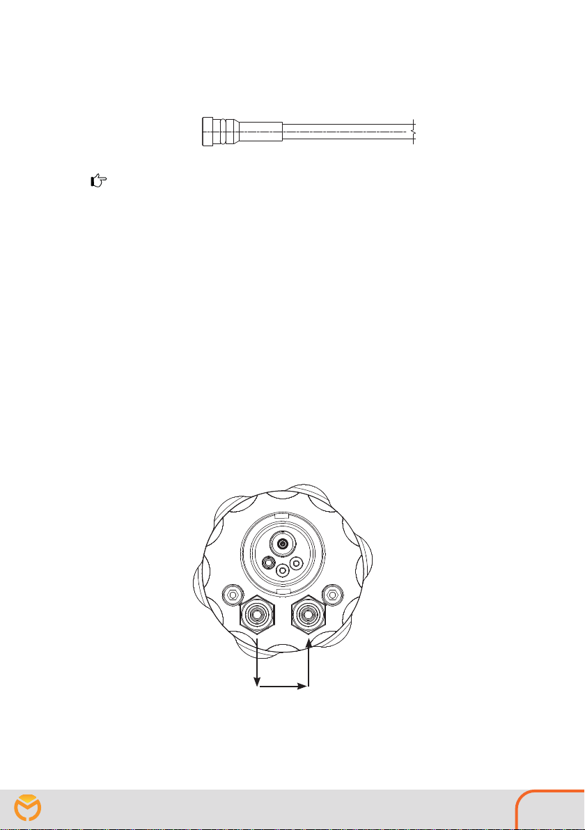
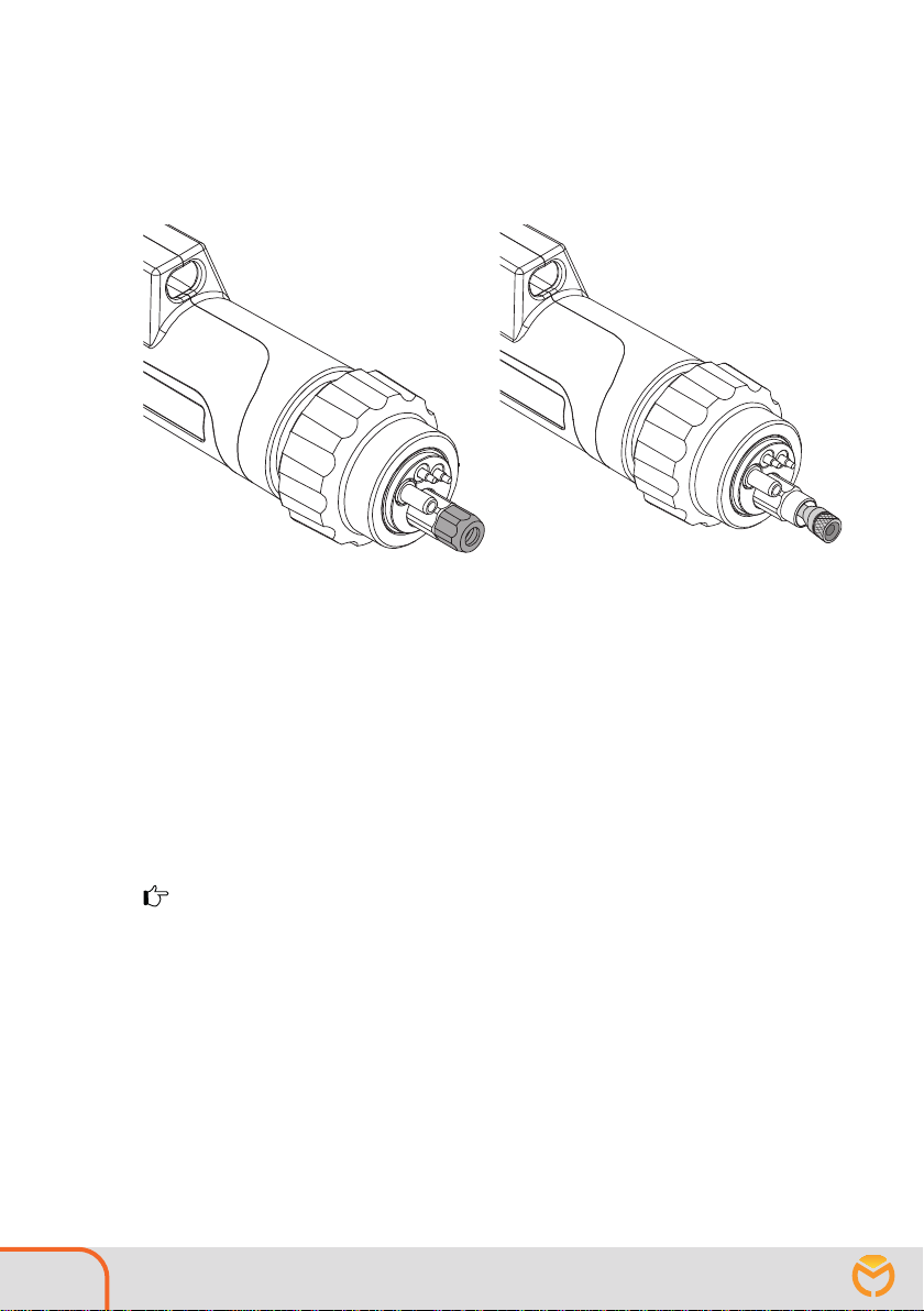
6.2. Connecting
Connect the hose pack of the intermediate drive to your wire feeder with a Euro plug (just like the
welding torch). Connect the two water connections (for the water-cooled intermediate drive) correctly.
Connect the motor / encoder plug with the corresponding connector of your machine.
Connect the welding torch (gas or liquid cooled) to the Euro plug of the intermediate drive.
For the connection of a gas-cooled welding torch, the water connections can be bridged in systems that
are intended for water cooling. This creates a connection between port A water supply (blue) and port
B water return (red). Application only when using a gas-cooled burner.
1
1
8Operating instructions Intermediate drive PushPull MECHAFIN AG 03 / 2023
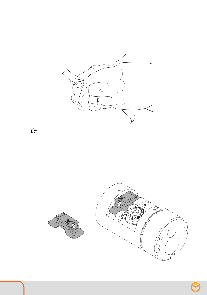
6.3. Introducing wire
Lay out the intermediate drive with stretched hose as straight as possible. Open the intermediate drive
in order to observe the correct wire feeding process. Place the wire reel in the feeding device of your
welding source. Deburr the cut welding wire with emery cloth or file. If the wire is deburred and reason-
ably straight, it will thread itself. In case of a fault, stop and insert the wire by hand into the wire guide.
NOTE
Deburr the interface on the wire every time the wire is changed.
6.4. Opening/closing the pressure arm
The wire can be extended in idle mode. In special cases you can open/close the pressure arm (dark grey)
manually. To do so, open the housing, unlock the bayonet and pull the slider back.
To open lift the pressure arm (dark grey) at position [1] with a slotted screwdriver.
To close, press the pressure arm down until it locks into place.

1
3
4
2
3
1
2
Operating instructions Intermediate drive PushPull MECHAFIN AG 03 / 2023 9
6.5. Changing the feed roller
Open the pressure arm. Open the fastening screw [1].
Remove the driving sprocket, then pull the feed roller [4] from the sprocket [3]. Then
replace the feed roller and reassemble in reverse order.
6.6. Exchanging the wire guide
Open the Allen screw [1]. Replace the wire guide [2]. For exact positioning, make sure that the notch
[3] is positioned under the Allen screw. Then carefully tighten the Allen screw again.
6.7. Exchanging the wire liner
10 Operating instructions Intermediate drive PushPull MECHAFIN AG 03 / 2023
Plastic wire guides with wire spiral attachment, can be used for aluminium, copper, nickel and stainless
steel wires. Lay the hose pack out straight. Then loosen the union nut (grey) with a size 12 open-end
wrench and remove it.
After removing the union nut the nipple of the wire guide spiral becomes visible. Use the same to pull
the wire guide spiral out of the hose pack.
There are wire guide spirals with firmly pressed nipples and wire guide spirals with clamping nipples. If the
nipple is not already firmly pressed, push it onto the wire guide spiral. Then insert the new wire guide spiral
intothehosepackandmeasurethelengththatprotrudesfromthecentraladaptertotheO-ringonthenipple.
Pull out the wire guide spiral again and cut off the measured length -1 cm, the cut edge must be
deburred.
Push the wire guide spiral back in and tighten the union nut again hand-tight with the open-end
wrench.
NOTE
Always check that the wire guide is fastened correctly.

Operating instructions Intermediate drive PushPull MECHAFIN AG 03 / 2023 11
6.8. Coolant (this is only required for liquid-cooled welding torches.)
WARNING
Risk of burns
Liquid-cooled torches will overheat if the coolant level is too low. Check
the coolant level in the cooling unit on a regular basis.
NOTE
The cooling system and welding torch must be thoroughly rinsed and filled every time initial installa-
tion is carried out, or whenever the hose pack is changed.
CAUTION
Material damage may occur
Damage to feed device and torch due to defective coolant connection. Be mindful of the flow and
return coolant connections on the cooling unit.
Coolant flow blue
Coolant return red
• Connect the hose on the welding torch from the blue coolant flow to blue quick-coupling NW5 on the
welding power source's cooling unit.
• Connect the hose on the welding torch from the red coolant return to the red quick-coupling on the
welding power source's cooling unit.
The coolant system is connected.
• Now rinse the welding torch with coolant, top up coolant if required.
• To do this, run the welding machine's own coolant flow program 2 to 4 times.
• The longer the welding torch is, the longer the coolant rinsing program must be used.
6.9. Setting the shielding gas quantity
NOTE
The type and quantity of the shielding gas to be used always depends on the welding task.
NOTE
To prevent a blockage due to impurities in the inert gas supply, briefly open the cylinder valve before
connection and thus flush out any impurities. This ensures a safe gas flow afterwards. All inert gas
connections must be gas-tight!
6.10. Application
Connect the shielding gas cylinder to the welding power source or the feed unit, then adjust the gas
flow quantity to the shielding gas cylinder's pressure reducer.
NOTE
Check
• before connecting to the feed unit that the correct wire guide (guide spiral or plastic core) has been
installed for the appropriate wire type in the welding torch's hose pack.
• that the equipment parts have been fitted on the torch elbow for appropriate wire diameters.
• that cooling unit functionality is ensured with liquid-cooled welding torch designs.

12 Operating instructions Intermediate drive PushPull MECHAFIN AG 03 / 2023
7. The control unit
7.1. Overview
Front view
Rear view
7.2. Technical data
Protection type: IP67 (except debug BNC connectors)
Power supply: 100 .. 240 VAC, max. 2.0 A, 50/60 Hz
Fuse protection: 2.5 AT, 5 x 20 mm
Internal supply: 48 VDC, max. 1.6 A (75 W)
Reference input: 0 .. ±50 V, max. 5 mA
Motor output: ±3.6 V .. ±48 V, max. 3 A, software limited to 60 W
Max. motor acceleration: 30 m/min/s
Push-pull speed: ±1 m/min .. ±30 m/min
Fuse
On
O
DC In
DC-Motor
Reference
Operating instructions Intermediate drive PushPull MECHAFIN AG 03 / 2023 13
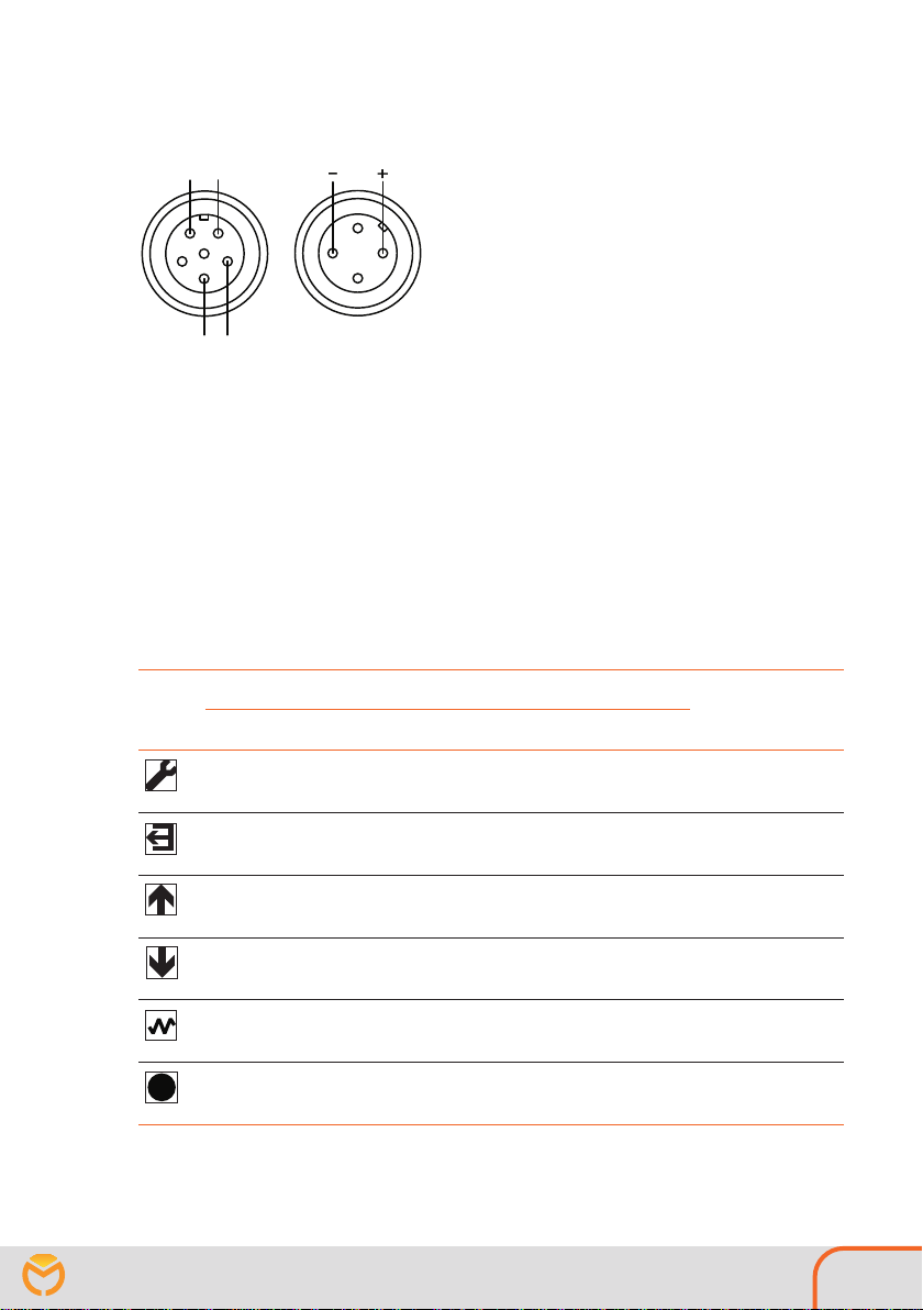
7.3. Pin assignment
Reference motor
Test contact
The test contact of the reference connector is used for connection detection of the reference cable. The
two pins must be connected directly in the connector. The reference cable is connected to the power
supply (+/-) at the master motor of the feed unit in the welding power source with connection to the
supplied cable clamps.
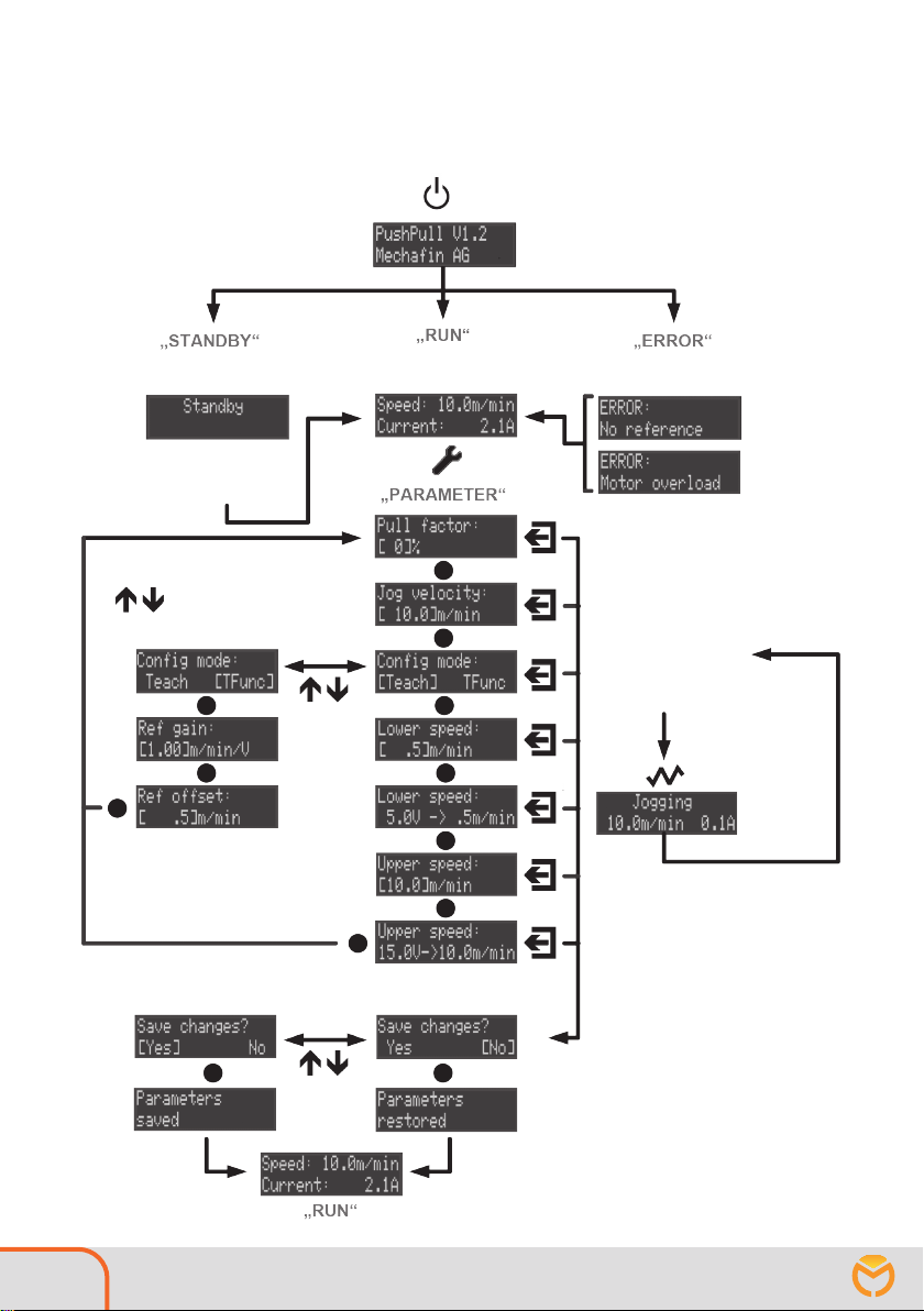
7.4. Operating the control unit
The push-pull device is entirely operated with six push buttons. There are five different program modes:
Standby, Run, Parameter, Setup and Error. The button functions depend on the current program mode.
The table below provides an overview:
Program mode Button > 2s
press
Button Run / Standby Parameter / Setup Error
Change to
„Parameter“
status
no function
Change to
„Parameter“
status
no function
no function Back to „Run“ no function no function
no function Increase parameter
value no function Increase parameter
value quickly
no function Reduce parameter value no function Quickly reduce
parameter value
Switch on
push-pull
(Jog function)
no function
Switch on
push-pull
(Jog function)
Switch on
push-pull
(Jog function)
no function Confirm set parameter,
jump to next parameter no function no function
14 Operating instructions Intermediate drive PushPull MECHAFIN AG 03 / 2023
7.5. Operation overview
Operation in regular mode
Display for
5 seconds
No reference
Signal present
As soon as the reference signal
is present, automatic change
to "RUN" mode
Push-pull in operation
As soon as the error is eliminated,
automatic change to the
"STANDBY" or "RUN" mode
"STANDBY" mode
"RUN" mode
"Error" mode
The parameters can be
adjusted with the
"UP" and "DOWN" buttons.
Display for
3 seconds
Operating instructions Intermediate drive PushPull MECHAFIN AG 03 / 2023 15
Operation in setup mode
By pressing the button during
the welding process, you enter
"SETUP MODE" for advanced settings.
Display for
3 seconds
Display for
3 seconds
Display for
3 seconds
The cable length is adjust here.
The cable length is calculated on the basis of
the following formula:
Length (m) x 0.08 + 3.4
5 m = value 3.8
10 m = value 4.2
15 m = value 4.6
20 m = value 5.0
25 m = value 5.4
The value in the scheme on the right corre-
sponds to a length of 20 m

16 Operating instructions Intermediate drive PushPull MECHAFIN AG 03 / 2023
7.6. Program modes
Standby mode
If the reference cable is connected, but no reference signal is present at the
input, the control unit is in standby mode. In this state the motor on the
push-pull unit is switched on and off. As soon as a voltage is measured at
the "Reference" input, the unit automatically switches to run mode and the
push-pull unit runs at the preset speed.
Run mode
In run mode, the push-pull unit operates at the speed specified at the "Ref-
erence" input. The current speed and motor current are shown on the dis-
play.
Parameter mode Pull factor: This value is used to set the percentage by which the push-pull
unit should run faster than the specified reference speed of the welding
machine. Value range: [0..30] %
Jog velocity Jog velocity: Push-pull velocity in jog mode. By pressing the Jog button
the program leaves the Run mode and the push-pull unit runs with the
speed set in this parameter. By entering negative values, the push-pull unit
can also be operated in the opposite direction.
Value range: ± [0..30] m/min
Teach config mode
In [Teach] config mode, a straight line equation for the speed control of the
push-pull unit is calculated on the basis of two defined speeds, depending
on the specified voltage at the reference input. For this purpose, the current
speed of the push-pull unit must be configured for two given reference
voltages, „Lower UREF“ and „Upper UREF“. . These recorded values must be
entered in the corresponding parameters „Lower speed“ and „Upper speed“.
[Teach] procedure
Lower
speed
Upper
speed
Lo
wer
U
REF
Upper
U
REF
v
UREF
Gain
Offset
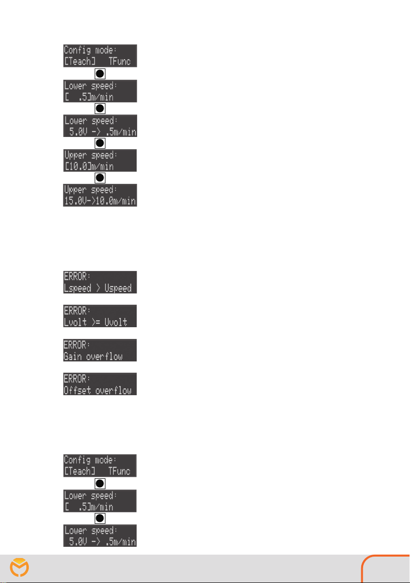
Operating instructions Intermediate drive PushPull MECHAFIN AG 03 / 2023 17
1.) Select [Teach] config mode
2.) Lower speed: Lower speed reference value.
Value range: [0.1..30] m/min
As a check, the measured reference voltage is displayed at the current
speed „Lower speed“.
3.) Upper speed: Upper speed reference value.
Value range: [0.1..30] m/min
For control purposes, the measured reference voltage is displayed at
the current speed „UPPER speed“.
When saving the parameters, the two straight line points are converted
into gain and offset values and stored in the memory.
Possible error messages after setting the [Teach] parameters:
Ensure that the following conditions are fulfilled for the above men-
tioned parameters:
Lower speed ≤Upper speed
Lower UREF < Upper UREF
If these conditions are not fulfilled when exiting the parameter set-
tings, an error message is output (see images on the left).
If the calculated gain or offset is too high, this is also indicated by a
message. In all cases, after three seconds the system switches back to
the „Lower speed“ parameter.
If the dependence of reference voltage and speed is known, it can be
entered directly in „[TFunc] config mode“ using the two parameters
Offset and Gain.
1.) Select [Teach] config mode
2.) Ref gain: known gain of the line equation
Value range: [0.1..5.0] m/min/V
3.) Ref offset: known OFFSET of the line equation
Value range: ± [0..30.0] m/min

18 Operating instructions Intermediate drive PushPull MECHAFIN AG 03 / 2023
Setup mode:
Setup mode: In „Setup mode“ adjustments can be made to adjust the
push-pull control to a specific push-pull unit. These parameters should
normally only be changed by the manufacturer.
Vel. threshold: As long as the reference voltage or the target speed is
below the set threshold value, the push-pull unit is inactive („Stand-
by“).
PushPull gain: This parameter is used to adjust the gain of the transfer
function between the push-pull control and the push-pull motor.
PushPull offset: With this parameter the offset of the transfer func-
tion between the push-pull control and the push-pull motor can be set.
Accel. ramp: This value determines the steepness of the acceleration
ramp in PWM steps per millisecond (see below). Caution: Higher values
lead to higher load on the electronic components.
Decel. ramp: Decel. ramp: This value determines the steepness of the
deceleration ramp in PWM steps per millisecond (see below).
Caution: Higher values lead to higher load on the electronic com-
ponents.
I*R gain: This parameter sets the gain of the I*R compensation.
Pos. I offset: Correction value of the current measurement for positive
output voltages.
Neg.I offset:Correction value of the current measurement for negative
output voltages.
Supply Voltage: This value is used to control the internal
power supply.
Factory Reset: Default values are loaded for all parameters.
Note on the acceleration ramps:
The full range of the output voltage extends over 32,768 PWM steps.
A speed change of 1 m/min corresponds approximately (depending on
the load) to 1100 PWM steps. Thus a value of 40 steps/ms leads to an
acceleration ramp of about 35.5 m/min/s. An acceleration of 0 to 10 m/
min takes 282 ms.
Operating instructions Intermediate drive PushPull MECHAFIN AG 03 / 2023 19
Default values
A "Factory reset" loads the following parameter values:
Pull factor: [10] %
Jog velocity: [10] m/min
Ref gain: [0.2] m/min/V
Ref offset: [-0.3] m/min
Vel. Threshold: [0.3] m/min
PushPull gain: [1.65] V/m/min
PushPull offset: [0.0] m/min
Accel. ramp: [40] steps/ms
Decel. ramp: [200] steps/ms
I*R gain: [5] V/A
Pos. I offset: [0] A
Neg. I offset: [0] A
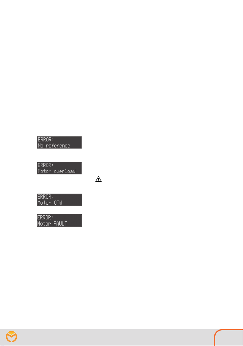
Error mode
No reference: The cable at the reference input is not connected. This is
detected by a wire jumper in the cable connector. As soon as the cable
is plugged in, the program returns to Run mode.
Motor overload: The motor was overloaded over a longer period of
time. The motor is switched off.
Attention: After about 30 seconds the motor is switched on again
and the program returns to Run mode.
Motor OTW: Over temperature warning of the motor driver on the
MMU 01 electronics. As soon as the temperature is back in the permit-
ted range, the program returns to the „Run“ state.
Motor FAULT: Protection mechanism of the motor driver on the MMU
01 electronics has responded, the motor is switched off immediately.
The error is cleared once the unit is switched into Standby mode
Table of contents
Popular Welding Accessories manuals by other brands


Lincoln Electric
Lincoln Electric ZIPLINE BOOM PACKAGE Operator's manual

RUD
RUD PowerPoint WPP Series Translation of the original instructions

dymax
dymax BlueWave Dymax Unpacking and setup instructions

Miller
Miller Classic Clearlight owner's manual

Würth
Würth WSH III 5-13 instruction manual

Lincoln Electric
Lincoln Electric W000315558 Safety instruction for use and maintenance


