Mecon mag-flux F5 User manual
MeconGmbH Phone +49(0)223760006-0 Fax +49(0)223760006-40 page 1to4
Röntgenstraße 105 www.mecon.de info@mecon.de Mecon01/2007
D-50169Kerpen
ElectromagneticflowSensor
mag
-
flux
F5
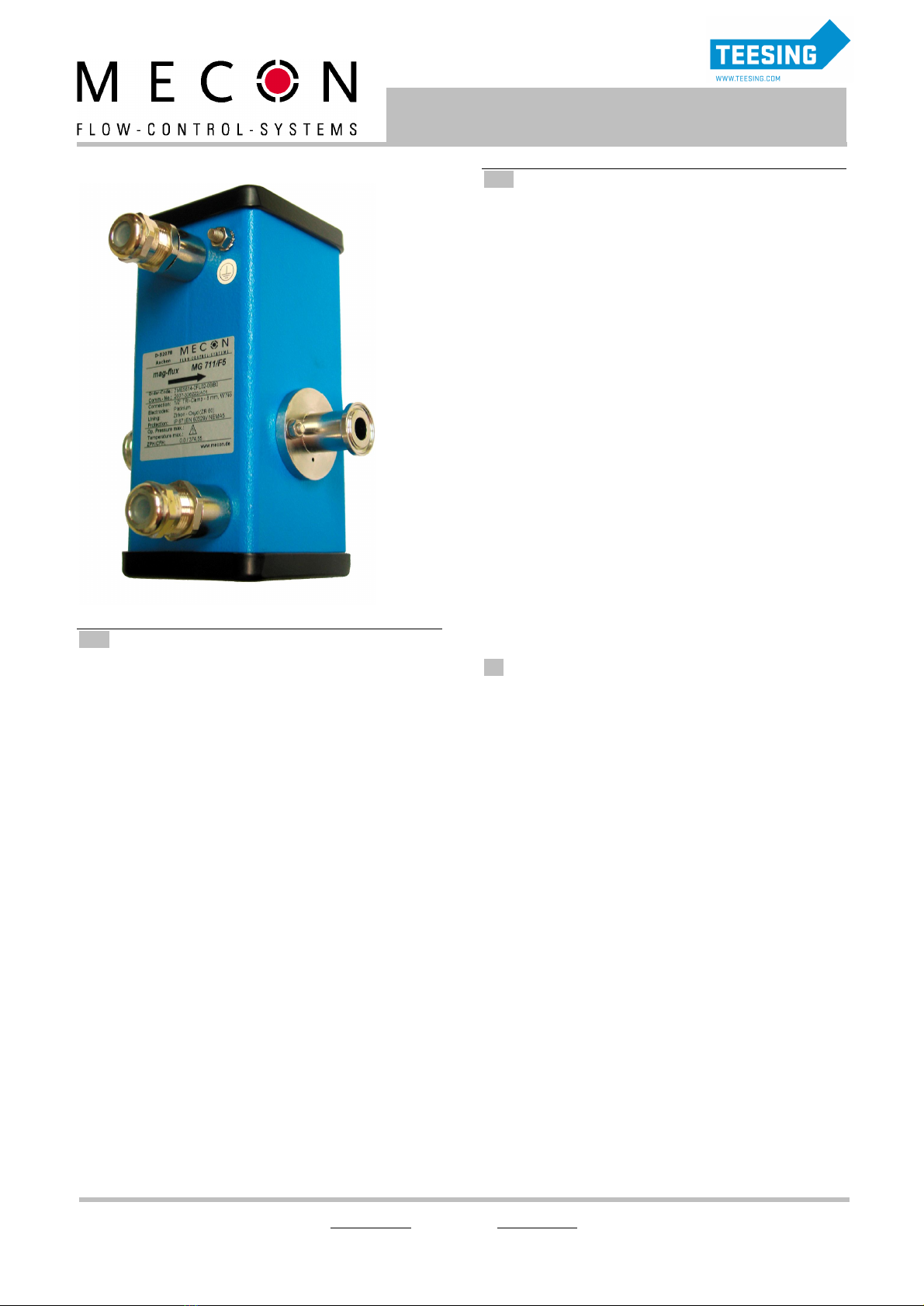
Fig.1electromagneticflowsensor mag-flux F5
__ Application
Electromagneticflowmetersaresuitableformeasuringthe flow
ofalmostall electricallyconductingliquids,aswellassludges,
pastesandslurries.
Aprerequisiteisthat the mediummusthaveacertainminimum
conductivity.The temperature,pressure,viscosityanddensity
have noinfluence onthe result.
Thisspecialdesignofan electromagneticflowmeter(MID)is
particularlysuitableformeasuringtheflowofextremelysmall
quantitiesandespeciallyforusewith proportioningandbatching
systems.Inconjunctionwith thetransmittersIntermag
2/Transmag2,complextasks can besolvedusingtheintegral
softwareforbatchingapplications.Typicalapplicationscan be
foundinthefoodindustry,thedosingofchemicalsin
photographicsystems,andthedosingofmedicinesinmedical
fields.
When usingthealternatingfieldtechnique with thetransmitter
Transmag2,even verysmallflowscan beexactlymeasuredasa
resultofthe largermagneticfieldandthe zerostability.
The flowsensors mag-flux F5areusedmainlyinthefollowing
industries:
·Waterandwaste waterplants
·Chemicalandpharmaceuticalindustry
·Food- andbeverage industry
·Mining,cementandmineralmaterials
·Pulp- andpaperindustry
·Steelindustry
·Powergenerationanddistribution.
The flowsensorarecombinedwith thetransmittersIntermag
2/Transmag2andare only available asremoteversions.
__ Special features
·Meteringtubemadefromhighcorrosion-andtemperature
resistant zirconium oxide
·Meteringtube innerdiameter2mm(0,078")andabove
·smallestmeasuringranges:
o0to5l/h(0to0,022 USgpm) with constantfield
o0to3l/h(0to0,0132USgpm) withalternatingfield
·verylowminimum conductivity:
o10 S/cm with constantfield
o0,1 S/cmwith alternatingfield
·robustandinterference-freeasaresultofclosedsteel
housing
·differentprocessconnectionsandmaterials
oThread:DIN,NPT,BSP
oFlange: DIN,ANSI,JIS
oClamp
oDIN11851
oandmoreuponrequest
·differentprocessconnectionmaterials
oMat.No. 1.4571
oHastelloy C4W.Nr.2.4610
oPVDFwith earthingringmadefromHastelloyC4
mat.No. 2.4610
oTitanium
oandmoreuponrequest
____________________________________________________________
__ Noteof application
·The operatorofthesemeasuringinstrumentsisresponsiblefor
suitability,properuseandcorrosionresistanceoftheused
materialswith regardtothemeasuringmaterial.Itmustbe
ensuredthatthematerialsselectedforthemeterpartsin
contactwiththemediumaresuitablefortheusedprocess
media.
·Beforereplacingthe measuringtubes,checkthatthe meteris
freeof hazardousmediaandisnotpressurized.
·The unitmayonlybeusedwithinthepressureandvoltage
limitsspecifiedonthe ratingplate.
·The flowmetercomplieswith therequirementsofthePressure
EquipmentDirective97/23/EC,article3,paragraph3.The
mosthazardouspermissiblemediaarethe fluidsdefinedin
group1.
·Provideatouchguardforsurfacetemperaturesof>70°C.
Thistouchguardmustbedesignedinawaythat the max.
allowable ambienttemperature ontheunitisnotexceeded.
·The sensormustnotbeaffectedbyexternalloads.
·The unitsaredesignedforpredominantly recumbentload.
WWW.TEESING.COM | +31 70 413 07 50

MeconGmbH Phone +49(0)223760006-0 Fax +49(0)223760006-40 page 2to4
Röntgenstraße 105 www.mecon.de info@mecon.de Mecon01/2007
D-50169Kerpen
ElectromagneticflowSensor
mag
-
flux
F5
__ Installation
The measuringprincipleisgenerallyindependentofthe flow
profile.Ideally,thedeviceshouldbeinstalledinapipeline,which
hassufficientstraight tubingbeforeandafterthe measuring
point.Ingeneral,aninletpath ofmin.5xdia.andanoutflow
zone ofmin.2-3x dia.isrequired.
Providedthatconstantturbulencedoesnotenterthe areain
whichthemeasurementtakesplace(e.g.afterelbows,during
tangentialfeedsorifthe valveinfrontofthesensorispartially
open).Insuchcasesmeasurestonormalize theflowprofileare
necessary.Suitable measuresinthisrespectare:
·increasingtheinletandoutletzones
·usingflowconditioners
·reducingthe innerdiameterofthe pipe
Fig.2Installationin horizontalandverticalpipelines
Installationmaybehorizontalorvertical(Fig.2)butitmustbe
ensuredthat theaxesoftheelectrodesrun horizontally(the
directionarrowmarks the electrodeaxes) toavoidmeasuring
errorsduetodepositsorairbubblesonthe electrodes.
Fig.3Installation between pipeelbows,valvesandpumps
The inletandoutletzonesmustbekeptstraight (Fig.3).
Fig.4Installationin aconstantly filledpipe
The flowmeasuringdevicemustbeinstalledsothatthe
measuringpipecannotrunemptyandisalways filledwith
medium.Thesensormustbeinstalledinaculvertinthecaseof
an unfilledpipe oronly afreelevelline (outlet).
Fig.5Installationin pipeswithout emptying
The sensorshouldnotbeinstalledinpipesectionswith afree
pipeoutletwhichcouldrunempty(e.g.downpipes).When
installinginadownpipemakesurethat the pipeisalways filled
100% with the medium.
Fig.6Installation at the highest point
Avoidinstallationat the highestpoint ofthepipedue to
accumulationof gas.
Fig.7Installation of severalsensors,eitherin seriesorin parallel
Ifseveralsensorsareseriesconnected,thedistancebetween the
individualsensorsmustbeatleastequaltothelength ofone
sensor.Iftwoormoresensorsaretobeconnectedinparallel,
thedistancemustbe atleast1m.
WWW.TEESING.COM | +31 70 413 07 50
MeconGmbH Phone +49(0)223760006-0 Fax +49(0)223760006-40 page 3to4
Röntgenstraße 105 www.mecon.de info@mecon.de Mecon01/2007
D-50169Kerpen
ElectromagneticflowSensor
mag
-
flux
F5
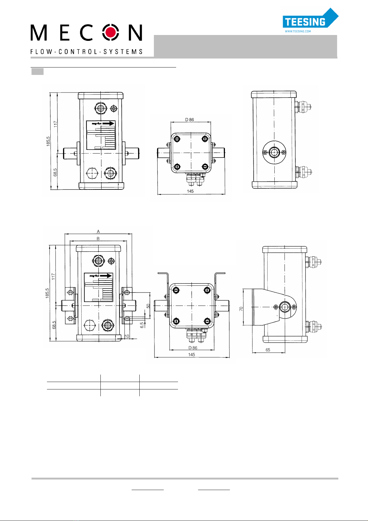
__ Dimensions
X1: if flange connectionmaterialisPVDF,installationdimension
is160mm!
Connectionmaterial DimensionA DimensionB
Metal 133 132
Plastic 140 120
Fig.2ElectromagneticflowSensor
mag
-
flux
F5(without wallmount),dimensionsin mm
Fig.3ElectromagneticflowSensor
mag
-
flux
F5(with wallmount),dimensionsinmm
X
1
X
1
WWW.TEESING.COM | +31 70 413 07 50

MeconGmbH Phone +49(0)223760006-0 Fax +49(0)223760006-40 page 4to4
Röntgenstraße 105 www.mecon.de info@mecon.de Mecon01/2007
D-50169Kerpen
ElectromagneticflowSensor
mag
-
flux
F5
__ TechnicalData
Applicationfield see page1
Measuringprinciple pulsedconstant field(DC)
pulsedalternatingfield(AC)
Inlet
Nominaldiametermeteringtube Measuringrange
Constant field Alternatingfield
2mm (0,078”) 5-110 l/h 3 -110 l/h
4 mm (0,156”) 25 -450 l/h 15 -450 l/h
8 mm (0,312”) 100 -1800 l/h 60 -1800 l/h
12 mm (0,47”) 200 -4000 l/h 120 -4000 l/h
Measuringaccuracy
Errorof measurement ±0,5%of measuredvalue
0,25 m/sto10 m/s
Repeat accuracy ±0,15 %of measuredvalue
0,25 m/sto10 m/s
Operational conditions
Mountingposition verticalorhorizontal
Max.operatingtemperature 150°C/302°F
Pressurelimits 25 bar/362,5psi
higheruponrequest
Temperature Max.pressure
°C °F Bar Psi
0-50 32 -122 10 145
60 140 8,5 123
70 158 7,5 109
80 176 6,5 94
90 194 5,5 80
100 212 4,5 65
110 230 3,8 55
Pressure/temperaturelimitswith
PVDFconnections(DIN8062)
120 248 3,0 44
Protection class IP67/IP68
Minimumconductivity
·with constant field
·with alternatingfield
>10 S/cm
>0,1 S/cm
Specifications
Design Fully-weldedsteelfittingwith cover
madeof aluminium
Weight approx.3kg
Cableinlet
·with constant field
·with alternatingfield
2x M16 x 1,5/2x½”NPT
3x M16 x 1,5/3x½”NPT
Material
·Meteringtube
·Sensorhousing
·Process connection
Zirconiumoxide
Steel
Stainless Steel,Hastelloy,PVDF
Electrodes
·Material
·Design
Platinum99,9%,sintered
Flat electrode
__ Orderingdata
ElectromagneticflowSensor
mag-flux
F5
M
A
G
5
6
1
-
0
0
-
0
Measuringprinciple
•alternatingfield
3
•constantfield
4
Nominaldiameterofmeteringtube
•2mm
D
•4mm
E
•8mm
F
•12mm
G
Process connection
•G1/2,mat.No.1.4571
A
•G1/2,HC4(mat.No.2.4610)
B
•G1/2,PVDFwithHC4-earthingrings(mat..No.2.4610)
C
•G1/2,Titanium
S
•NPT1/2",mat.No.1.4571
D
•NPT1/2",HC4(mat.No.2.4610)
E
•NPT1/2",PVDFwithHC4-earthingrings(mat.No.2.4610)
F
•DN15 PN25 DIN2501,mat.No.1.4571
H
•DN15 PN25 DIN2501,HC4(mat.No.2.4610)
J
•DN15 PN25 DIN2501,
K
PVDFwithHC4-earthingrings(mat.No.2.4610)
•1/2"Tri-Clamp,mat.No.1.4571
L
•1"Tri-Clamp,mat.No.1.4571
N
•1/2"ANSIB16.5150RF,mat.No.1.4571
Q
•1/2"ANSIB16.5150RF,
T
PVDFwithHC4-earthingrings(mat.No.2.4610)
•otherconnections/materials
Z
Gasketmaterial
•EPDM
2
•Kalrez
3
Wallmount
•without
0
•with
1
Screwedgland
•M16x1,5
C
•NPT1/2"
B
Degree of protection
•IP67/NEMA5
B
•IP68/NEMA6mit5mfirmlyconnectedcable
C
•IP68/NEMA6mit10mfirmlyconnectedcable
D
Furtherdesigns
•Measuringrange<10l/h
A11
•TAGplateinscriptioninenglish
B11
•with3-pointcalibrationcertificate
B06
•with6-pointcalibrationcertificate
B07
•Silicone-freematerials
Y04
•TAGplatestainlesssteel
Y17
WWW.TEESING.COM | +31 70 413 07 50
Table of contents
Other Mecon Accessories manuals


