MEDC SM87BG User manual

© MEDC 2015 07/15
Please note that every care has been taken to ensure the accuracy of our technical manual. We do not, how-
ever, accept responsibility for damage, loss or expense result-ing from any error or omission. We reserve the
right to make alterations in line with technical advances and industry standards.
fÍÁÐÃÇÓÑÇÙÇÏÊÁÎÂÌÓÊÎÂÍÞÏÐËÔÐÙÏÐÓÔÊÏÂÚÇÅÐÔÇ×ÏÊÙÇÓÌÐÅÐÒÕÌÐÄÐÆÓÔÄÂÃÝÍÊÑÒÇÆÑÒÊÏÁÔÝ
ÄÓÇÄÐÉÎÐÈÏÝÇÎÇÒÝoÂÚÂÌÐÎÑÂÏÊÁÏÇÏÇÓÇÔÐÔÄÇÔÓÔÄÇÏÏÐÓÔÊÉÂÑÐÄÒÇÈÆÇÏÊÁÕÛÇÒÃÊÍÊ
ÒÂÓ×ÐÆÝÓÄÁÉÂÏÏÝÇÓÄÐÉÎÐÈÏÝÎÏÂÍÊÙÊÇÎÄÏÇÎÐÚÊÃÐÌÊÍÊÑÒÐÑÕÓÌÐÄnÝÐÓÔÂÄÍÁÇÎÉÂ
ÓÐÃÐË ÑÒÂÄÐ ÄÏÐÓÊÔÞ Ä ÏÇÅÐ ÊÉÎÇÏÇÏÊÁ Ó ÕÙÇÔÐÎ ÔÇ×ÏÊÙÇÓÌÐÅÐ ÑÒÐÅÒÇÓÓÂ Ê ÊÉÎÇÏÇÏÊÁ
ÑÒÐÎÝÚÍÇÏÏÝ×ÓÔÂÏÆÂÒÔÐÄ
Toutes les précautions ont été prises pour garantir la précision de cette notice technique. Toutefois, nous ne
saurions accepter de responsabilité à l’égard des dégâts, pertes ou frais résultant d’une quelconque erreur ou
omission. Nous nous réservons le droit d’apporter d’éventuelles modifications pouvant résulter de progrès
techniques ou de l’évolution des normes industrielles.
Wir möchten Sie darauf hinweisen, dass wir große Sorgfalt darauf verwendet haben, die Richtigkeit unserer
technischen Anleitung zu gewährleisten. Wir übernehmen jedoch keine Verantwortung für Schäden, Verluste
oder Kosten, die sich aus einem etwaigen Fehler oder einem Versäumnis ergeben. Änderungen die dem technischen
Fortschritt bzw. neusten Industrienormen entsprechen, behalten wir uns vor.
Tenga en cuenta que se han tomado todas las precauciones para garantizar la exactitud de nuestro manual
técnico. No obstante, no nos responsabilizamos de daños, pérdidas o costes resultantes de cualquier error u
omisión. Nos reservamos el derecho de realizar modificaciones en línea con los avances técnicos y las normas
de la industria.
Por favor, tenha em atenção que tivemos todo o cuidado para garantir a precisão do nosso manual
técnico. No entanto, não nos responsabil izamos por danos, perdas ou despesas resultantes de qualquer
erro ou omissão. Reservamo-nos o direito de fazer alterações conforme os avanços técnicos e padrões
industriais.
d
Technical Manual for the call points SM87BG/PB Exd versions
tÇ×ÏÊÙÇÓÌÐÇÒÕÌÐÄÐÆÓÔÄÐÌÊÉÄÇÛÂÔÇÍÁÎÄÇÒÓÊË60%*3%
Manuel Technique pour les versions Exd SM87BG/PB de Points d’Appel Manuel
Technische Anleitung für die Feuermelder SM87BG/PB Exd-Ausführungen
Manual técnico de los pulsadores SM87BG/PB versiones Exd
P technical manual. We do not, how-
e
möchten Sie darauf hinweisen, dass wir große Sorgfalt darauf verwendet haben, die Richtigkeit unserer
t
Versões Ex SM87BG/PB
P
d
Manual Técnico para o estação de alarme de uso geral

07/15 © MEDC 2015

English
1.0 INTRODUCTION
These manual fire alarm, emergency shutdown breakglass and pushbutton units have been designed for the
most arduous environmental conditions. The units are both easy to install and maintain. A choice of either
stainless steel or alloy makes the range suitable for both the offshore and onshore industries.
The units are available with the following options and features:
Lift flap
Duty label
Tag label
Earth continuity via internal/external earth studs
LED
End of Line and Series resistors and diodes
Switches (two switches, four poles maximum)
M20 or M25 gland entries in a range of positions, with a maximum of four
Optional momentary or latching with key reset actions
2.0 INSTALLATION
General
When installing and operating explosion-protected equipment, requirements for selection, installation and op-
eration should be referred to e.g. IEE Wiring Regulations and the ‘National Electrical Code’ in North America.
Additional national and/or local requirements may apply.
Ensure that all nuts, bolts and fixings are secure.
Ensure that only the correct listed or certified stopping plugs are used to blank off unused gland entry points
and that the NEMA/IP rating of the unit is maintained. MEDC recommend the use of a sealing compound such
as HYLOMAR PL32 on the threads of glands and stopping plugs in order to maintain the IP rating of the unit.
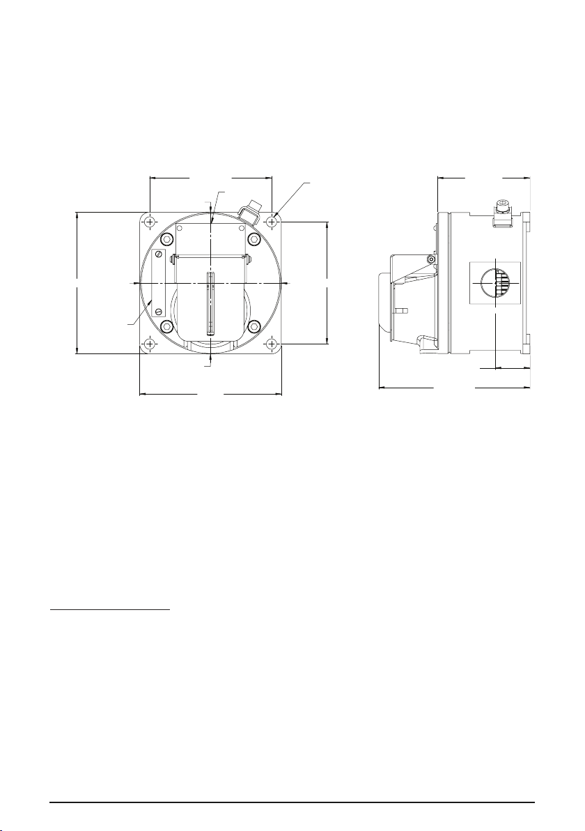
These alarm call points are designed to be directly mounted using the 4 off 9mm holes in the base of the unit.
Units may be mounted to vertical, horizontal or angled surfaces.
The holes have been designed to accept an M8 screw or bolt. MEDC recommend the use of stainless steel
screws.
Cable Termination
CAUTION: Before removing the cover assembly, ensure that the power to the unit is isolated.
Unscrew and remove the 4 off M6 screws (5.0mm A/F hexagon key) holding the cover assembly to the base.
Keep in a safe, accessible location.
Twist the cover assembly gently clockwise and anti-clockwise, whilst pulling it away from the base. Remove to
gain access to the interior.
Cable termination should be in accordance with specifications applying to the required application. MEDC rec-
ommends that all cables and cores should be correctly identified. Please refer to the wiring diagram provided
with the product.
Ensure that only the correct listed or certified cable glands are used and that the assembly is shrouded and
correctly earthed.
All cable glands should be of an equivalent NEMA/IP rating to that of the call point and integrated with the
unit such that this rating is maintained.
The internal earth terminal, where fitted, must be used for the equipment grounding connection and the
1
external terminal is for a supplementary bonding connection where local codes or authorities permit or require
such a connection.
© MEDC 2015 07/15

Once termination is complete, carefully push the cover assembly back onto the base, avoiding damage to the
mating surfaces. Ensure that the retaining strap is not trapped between the mating surfaces and that the o-ring
is correctly seated in its groove. Ensure the retaining strap and wires are clear of the microswitch actuator and
operating mechanism. Replace the 4 off M6 screws (5.0mm A/F hexagon key) into the holes in the cover as-
sembly and tighten evenly. Ensure the maximum gap of 0.15mm is maintained between the cover and the base
once assembled.
3.0 OPERATION
The operating voltage of the unit is stated on the unit label.
SM87BG GENERAL ARRANGEMENT
SM87 units - operationBG
The unit is operated by breaking the glass element in the front of the cover using the hammer attached to the
unit. If a lift flap has been specified, this will need to be raised first to gain access to the glass element.
SM87BG unit - resetting procedure
a. To replace the glass, a kit containing O-rings and glass is provided.
b. Unscrew and remove the circular bezel on the front of the unit.
c. Remove the original O-rings and glass and ensure the grooves in the bezel and cover are clean.
d. Fit the larger O-ring into the groove on the cover.
e. Fit the smaller O-ring into the groove on the underside of the bezel:-
i. Offer the O-ring up to the groove.
ii. Place thumbs of both hands side by side onto the O-ring
iii. Press the O-ring down into the groove circumference maintaining even pressure, forcing the O-ring into
the groove.
iv. The O-ring should be fully seated in the groove and not fall out when fitting the bezel to the cover.
v. Centralise the new glass element on the cover
f. Place the new glass element into position on the cover and assemble the bezel over the top of the glass
element
.
g. Ensure the glass element stays central on the cover by holding down the glass with thumb through the hole
in the centre of the bezel.
h. Carefully use the glass element to depress the plunger until the glass is in full contact with the cover O-ring.
Ensure there is an even gap around the glass.
Without allowing the glass element to move, screw down the bezel until the bottom of the bezel is tightened
against the cover.
S
07/15 © MEDC 2015

SM87PB units - resetting procedure
On units with a latching mechanism, once operated, the actuator remains in its depressed position. To reset
the call point, lift the flap on the front of the cover and insert the key (provided with the unit) into the slot in the
front face of the actuator. The key should be turned slightly to locate it in the actuator and pulled back to the
initial position. The key can then be removed and the flap lowered.
4
SM87PB units - operation
The unit is operated by lifting the flap on the front of the cover, then depressing the steel actuator underneath.
Depending on the unit type ordered, the actuator will either remain in its depressed position (latching versions)
or return to its original position (momentary versions).
S
122 ±1
122 ±1
105 ±1 CRS
105 ±1 CRS
'T'
'B'
'R'
'L'
DUTY LABEL
TAG LABEL
(OPTIONAL)
9
1 FIXING HOLES
4 POSITIONS
36.5 ±1 (A)
30 ±1 (S)
87.5 ±2 (A)
81 ±2 (S)
138.5 ±3 (A)
132 ±3 (S)
SM87PB Turn & Push - operation
The unit is operated by lifting the flap on the front over, then turning the a tuator lo kwise 90° and
depressing the a tuator. The a tuator will remain in its depressed position.
SM87PB Turn & Push – resetting pro edure
On e operated the a tuator remains in its depressed position. To reset the all point, lift the flap on the front
over and pull the a tuator out from its depressed position. Turn the a tuator anti- lo kwise 90°. The lift flap
an then be lowered.
© MEDC 2015 07/15
SM87PB GENERAL ARRANGEMENT
SM87PB TURN AND PUSH GENERAL ARRANGEMENT

5.0 CERTIFICATION/APPROVALS
IECEx units
Certified to IEC 60079-0, IEC 60079-1 and IEC 60079-31
Ex d unit (IEC certification No. IECEx BAS 09.0060)
Ex d IIC T6 (-55°C to +55°C) Gb
Ex tb IIIC T85°C (-55°C to +55°C) Db IP66/IP67
or
Ex d IIC T5 (-55°C to +70°C) Gb
Ex tb IIIC T100°C (-55°C to +70°C) Db IP66/IP67
The IECEx certificate and product label carry the IECEx equipment protection level marking
Gb
Db
Where:
Gb signifies suitability for use in a Zone 1 surface industries area in the presence of gas.
Db signifies suitability for use in a Zone 21 surface industries area in the presence of dust
ATEX units
Certified to EN60079-0, EN60079-1 and EN60079-31
Ex d unit (ATEX certification No. Baseefa03ATEX0075)
Ex d IIC T6 (-55°C to +55°C) Gb
Ex tb IIIC T85°C (-55°C to +55°C) Db IP66/IP67
or
Ex d IIC T5 (-55°C to +70°C) Gb
Ex tb IIIC T100°C (-55°C to +70°C) Db IP66/IP67
The ATEX certificate and product label carry the ATEX group and category marking:
II 2 GD
Where:
Signifies compliance with ATEX
II Signifies suitability for use in surface industries
2 Signifies suitability for use in a zone 1 area
G Signifies suitability for use in the presence of gases
D Signifies suitability for use in the presence of dust
The ATEX certificate and product label also carry the following mark:
This signifies unit compliance to the relevant European directives, in this case 94/9/EC, along with the number
of the notified body issuing the EC type examination certificate.
1180
4.0 MAINTENANCE
During the working life of the unit, it should require little or no maintenance. However, if abnormal or unusual
environmental conditions occur due to plant damage or accident etc., then visual inspection is recommended.
If the unit requires cleaning, then only clean exterior with a damp cloth to avoid electro-static charge build up.
If a unit fault should occur, then the unit can be repaired by MEDC. All parts of the unit are replaceable.
If you acquired a significant quantity of units, then it is recommended that spares are also made available.
Please discuss your requirements with the Technical Sales Engineers at MEDC.
07/15 © MEDC 2015

ÒÕÓÓÌÊË
(%'xx{z{~{
oÂÓÔÐÁÛÊÇÕÓÔÒÐËÓÔÄÂÒÕÙÏÐËÑÐÈÂÒÏÐËÓÊÅÏÂÍÊÉÂØÊÊÑÒÇÆÕÓÎÂÔÒÊÄÂàÛÊÇÒÂÉÃÊÄÂÏÊÇ
ÓÔÇÌÍÂÊÏÂÈÂÔÊÇÌÏÐÑÌÊÂÄÂÒÊËÏÐÅÐÄÝÌÍàÙÇÏÊÁÒÂÉÒÂÃÐÔÂÏÝÆÍÁÓÂÎÝ×ÔÁÈÇÍÝ×ÕÓÍÐÄÊË
ÐÌÒÕÈÂàÛÇËÓÒÇÆÝÔÊÕÓÔÒÐËÓÔÄÂÍÇÅÌÐÊÕÓÔÂÏÂÄÍÊÄÂÔÞÊÐÃÓÍÕÈÊÄÂÔÞdÐÉÎÐÈÏÐÓÔÞ
ÄÝÃÐÒÂÄÌÂÙÇÓÔÄÇÌÐÏÓÔÒÕÌØÊÐÏÏÐÅÐÎÂÔÇÒÊÂÍÂÏÇÒÈÂÄÇàÛÇËÓÔÂÍÊÊÍÊÓÑÍÂÄÂÑÐÉÄÐÍÁÇÔ
ÊÓÑÐÍÞÉÐÄÂÔÞÊ×ÄÐÔÒÂÓÍÁ×ÑÒÐÎÝÚÍÇÏÏÐÓÔÊÅÆÇÒÂÃÐÔÝÎÐÅÕÔÑÒÐÊÉÄÐÆÊÔÞÓÁÌÂÌÄ
ÎÐÒÓÌÊ×ÕÓÍÐÄÊÁ×ÔÂÌÊÏÂÓÕÚÇ
uÓÔÒÐËÓÔÄÂÄÝÑÕÓÌÂàÔÓÁÓÐÓÍÇÆÕàÛÊÎÊÄÐÉÎÐÈÏÐÓÔÁÎÊÊÖÕÏÌØÊÁÎÊ
qÐÆÜÇÎÏÝËÛÊÔÐÌ
ÒÍÝÌÓÒÂÃÐÙÊÎÊ×ÂÒÂÌÔÇÒÊÓÔÊÌÂÎÊ
ÔÊÌÇÔÌÂÓÎÂÒÌÊÒÐÄÌÐË
iÂÉÇÎÍÇÏÊÇÑÒÊÑÐÎÐÛÊÄÏÕÔÒÇÏÏÊ×ÏÂÒÕÈÏÝ×ÉÂÉÇÎÍÁàÛÊ×ÚÔÝÒÇË
sjf
lÐÏÇÙÏÝÇÊÆÐÃÂÄÐÙÏÝÇÒÇÉÊÓÔÐÒÝÊÆÊÐÆÝ
qÇÒÇÌÍàÙÂÔÇÍÊÆÄÂÑÇÒÇÌÍàÙÂÔÇÍÁÓÙÊÓÍÐÎÑÐÍàÓÐÄÆÐÙÇÔÝÒÇ×
sÂÍÞÏÊÌÐÄÝÇÄÄÐÆÝÒÂÉÎÇÒÐÎ0ÊÍÊ0ÄÑÐÍÐÈÇÏÊÁ×ÎÂÌÓÊÎÂÍÞÏÐÇÙÊÓÍÐÌÐÔÐÒÝ×ÏÇ
ÑÒÇÄÝÚÂÇÔÙÇÔÝÒÇ×
qÒÇÆÕÓÎÐÔÒÇÏÏÝÇÐÔÆÇÍÞÏÝÎÉÂÌÂÉÐÎÌÒÂÔÌÐÄÒÇÎÇÏÏÝÇÊÍÊÖÊÌÓÊÒÕÇÎÝÇÆÇËÓÔÄÊÁF
ÄÐÉÄÒÂÔÐÎÄÊÓ×ÐÆÏÐÇÓÐÓÔÐÁÏÊÇÓÑÐÎÐÛÞàÌÍàÙÂ
)%'vxv
×ïÖÕÞãêäæâÖìÞÕ
tÒÇÃÐÄÂÏÊÁÑÒÇÆÜÁÄÍÁÇÎÝÇÌÄÝÃÐÒÕÕÓÔÂÏÐÄÌÇÊßÌÓÑÍÕÂÔÂØÊÊÄÉÒÝÄÐÉÂÛÊÛÇÏÏÐÅÐ
ÐÃÐÒÕÆÐÄÂÏÊÁÆÐÍÈÏÝÓÐÐÔÄÇÔÓÔÄÐÄÂÔÞ©oÐÒÎÂÔÊÄÏÝÎÔÒÇÃÐÄÂÏÊÁÎÌÎÐÏÔÂÈÕ
ßÍÇÌÔÒÊÙÇÓÌÊ×Ó×ÇÎjÏÓÔÊÔÕÔÂÊÏÈÇÏÇÒÐÄßÍÇÌÔÒÊÌÐÄ,((ªÊ©oÂØÊÐÏÂÍÞÏÝÎ
ßÍÇÌÔÒÐÔÇ×ÏÊÙÇÓÌÊÎÏÐÒÎÂÔÊÄÂΪÆÍÁsÇÄÇÒÏÐËbÎÇÒÊÌÊoÇÐÃ×ÐÆÊÎÐÕÙÊÔÝÄÂÔÞÔÂÌÈÇ
ÏÂÍÊÙÊÇÆÐÑÐÍÏÊÔÇÍÞÏÝ×ÖÇÆÇÒÂÍÞÏÝ×ÊÊÍÊÎÇÓÔÏÝ×ÔÒÇÃÐÄÂÏÊË
qÒÐÓÍÇÆÊÔÇÙÔÐÃÝÄÓÇÅÂËÌÊÃÐÍÔÝÊÌÒÇÑÍÇÏÊÁÃÝÍÊÏÂÆÇÈÏÐÉÂÔÁÏÕÔÝ
qÒÐÓÍÇÆÊÔÇÙÔÐÃÝÆÍÁÉÂÅÍÕÚÌÊÏÇÊÓÑÐÍÞÉÕÇÎÝ×ÓÂÍÞÏÊÌÐÄÝ×ÄÄÐÆÐÄÊÓÑÐÍÞÉÐÄÂÍÊÓÞ
ÔÐÍÞÌÐÑÒÂÄÊÍÞÏÐÌÂÔÂÍÐÅÊÉÊÒÐÄÂÏÏÝÇÊÍÊÓÇÒÔÊÖÊØÊÒÐÄÂÏÏÝÇÉÂÅÍÕÚÌÊÊÙÔÐÃÝÃÝÍ
ÄÝÆÇÒÈÂÏÌÍÂÓÓÉÂÛÊÔÝ1(0$,3ÕÓÔÒÐËÓÔÄÂlÐÎÑÂÏÊÁ0('&ÒÇÌÐÎÇÏÆÕÇÔÏÂÏÇÓÔÊ
ÅÇÒÎÇÔÊÌ+</20$53/ÏÂÒÇÉÞÃÕÓÂÍÞÏÊÌÐÄÊÉÂÅÍÕÚÇÌÓØÇÍÞàÓÐ×ÒÂÏÇÏÊÁÌÍÂÓÓÂ
ÉÂÛÊÔÝ,3ÕÓÔÒÐËÓÔÄÂ
fÂÏÏÝÇÔÒÇÄÐÈÏÝÇÊÉÄÇÛÂÔÇÍÊÒÂÓÓÙÊÔÂÏÝÏÂÕÓÔÂÏÐÄÌÕÓÊÓÑÐÍÞÉÐÄÂÏÊÇÎÐÔÄÇÒÓÔÊË
ÒÂÉÎÇÒÐÎÎÎÄÃÂÉÐÄÐËÙÂÓÔÊÕÓÔÒÐËÓÔÄÂ
uÓÔÒÐËÓÔÄÂÎÐÅÕÔÎÐÏÔÊÒÐÄÂÔÞÓÁÏÂÄÇÒÔÊÌÂÍÞÏÝ×ÅÐÒÊÉÐÏÔÂÍÞÏÝ×ÑÐÄÇÒ×ÏÐÓÔÁ×ÂÔÂÌÈÇ
ÏÂÑÐÄÇÒ×ÏÐÓÔÁ×ÒÂÓÑÐÍÐÈÇÏÏÝ×ÑÐÆÕÅÍÐÎÌÄÇÒÔÊÌÂÍÊ
pÔÄÇÒÓÔÊÁÒÂÓÓÙÊÔÂÏÝÑÐÆÄÊÏÔÝÊÍÊÃÐÍÔÝÒÂÉÎÇÒÐÎ00('&ÒÇÌÐÎÇÏÆÕÇÔÊÓÑÐÍÞÉÐÄÂÔÞ
ÄÊÏÔÝÊÉÏÇÒÈÂÄÇàÛÇËÓÔÂÍÊ
Ö×ÛáòãñߨØäÚ
|ÛæÛÚçãÕèÞÛâéÝáÖàæñîàÞé×ÛÚÞèÛçòØèäâ#íèäåÞèÖãÞÛéçèæäßçèØÖ
äèàáôíÛãä%
dÝÄÇÒÏÊÔÇÄÊÏÔÂ0ÒÂÉÎÇÒÉÇÄÂÚÇÓÔÊÅÒÂÏÏÐÅÐÌÍàÙ³ÎÎÕÆÇÒÈÊÄÂÁÌÒÝÚÌÕÄ
ÓÃÐÒÇÏÂÕÓÔÂÏÐÄÐÙÏÐËÑÐÄÇÒ×ÏÐÓÔÊwÒÂÏÊÔÇÊ×ÄÃÇÉÐÑÂÓÏÐÎÍÇÅÌÐÆÐÓÔÕÑÏÐÎÎÇÓÔÇ
pÓÔÐÒÐÈÏÐÑÐÄÐÒÂÙÊÄÂËÔÇÌÒÝÚÌÕÄÓÃÐÒÇÑÐÙÂÓÐÄÐËÓÔÒÇÍÌÇÊÑÒÐÔÊÄÏÇÇÑÒÊßÔÐÎ
ÄÝÔÂÓÌÊÄÂÁÇÇÊÉÃÂÉÐÄÐËÙÂÓÔÊuÆÂÍÊÔÇÇÇÙÔÐÃÝÑÐÍÕÙÊÔÞÆÐÓÔÕÑÌÄÏÕÔÒÇÏÏÇÎÕ
ÑÒÐÓÔÒÂÏÓÔÄÕ
© MEDC 2015 07/15

Ò Ò Õ
lÂÃÇÍÞÏÝËÄÄÐÆÆÐÍÈÇÏÓÐÐÔÄÇÔÓÔÄÐÄÂÔÞÓÑÇØÊÖÊÌÂØÊÁÎÒÂÉÒÂÃÐÔÂÏÏÝÎÆÍÁÌÐÏÌÒÇÔÏÐË
ÑÒÊÌÍÂÆÏÐËÉÂÆÂÙÊ0('&ÒÇÌÐÎÇÏÆÕÇÔÙÔÐÃÝÄÓÇÌÂÃÇÍÊÊÈÊÍÝÌÂÃÇÍÇËÃÝÍÊÆÐÍÈÏÝÎ
ÐÃÒÂÉÐÎÊÆÇÏÔÊÖÊØÊÒÐÄÂÏÝsÎÓ×ÇÎÕßÍÇÌÔÒÐÑÒÐÄÐÆÌÊÑÐÓÔÂÄÍÁÇÎÕàÄÎÇÓÔÇÓÊÉÆÇÍÊÇÎ
qÒÐÓÍÇÆÊÔÇÙÔÐÃÝÊÓÑÐÍÞÉÐÄÂÍÊÓÞÔÐÍÞÌÐÑÒÂÄÊÍÞÏÐÌÂÔÂÍÐÅÊÉÊÒÐÄÂÏÏÝÇÊÍÊ
ÓÇÒÔÊÖÊØÊÒÐÄÂÏÏÝÇÌÂÃÇÍÞÏÝÇÕÑÍÐÔÏÇÏÊÁÊÙÔÐÃÝÕÉÇÍÃÝÍßÌÒÂÏÊÒÐÄÂÏÊÑÒÂÄÊÍÞÏÐ
ÉÂÉÇÎÍÇÏ
dÓÇÌÂÃÇÍÞÏÝÇÕÑÍÐÔÏÇÏÊÁÆÐÍÈÏÝÓÐÐÔÄÇÔÓÔÄÐÄÂÔÞÌÍÂÓÓÕÉÂÛÊÔÝ1(0$,3ÊÉÄÇÛÂÔÇÍÁÊ
ÃÝÔÞÄÓÔÒÐÇÏÝÄÕÓÔÒÐËÓÔÄÐÌÂÌÔÐÅÐÔÒÇÃÕÇÔßÔÐÔÌÍÂÓÓ
dÏÕÔÒÇÏÏÁÁÌÍÇÎÎÂÉÂÉÇÎÍÇÏÊÁÔÂÎÅÆÇÐÏÂÕÓÔÂÏÐÄÍÇÏÂÆÐÍÈÏÂÊÓÑÐÍÞÉÐÄÂÔÞÓÁÆÍÁ
ÉÂÉÇÎÍÇÏÊÁÐÃÐÒÕÆÐÄÂÏÊÁÂÄÏÇÚÏÁÁÌÍÇÎγÆÍÁÆÐÑÐÍÏÊÔÇÍÞÏÐÅÐÉÂÉÇÎÍÇÏÊÁÔÂÎÅÆÇ
ÎÇÓÔÏÝÇÉÂÌÐÏÝÊÍÊÄÍÂÓÔÊÑÐÉÄÐÍÁàÔÊÍÊÔÒÇÃÕàÔÏÂÍÊÙÊÁÔÂÌÐÅÐÓÐÇÆÊÏÇÏÊÁ
qÐÉÂÄÇÒÚÇÏÊÊÉÂÆÇÍÌÊÓÃÐÍÞÚÐËÐÓÔÐÒÐÈÏÐÓÔÞàÑÐÎÇÓÔÊÔÇÌÒÝÚÌÕÄÓÃÐÒÇÐÃÒÂÔÏÐ
ÏÂÐÓÏÐÄÂÏÊÇÓÔÂÒÂÁÓÞÏÇÑÐÄÒÇÆÊÔÞÓÐÑÒÁÅÂàÛÊÇÓÁÑÐÄÇÒ×ÏÐÓÔÊqÒÐÓÍÇÆÊÔÇÙÔÐÃÝ
ÖÊÌÓÊÒÕàÛÂÁÓÌÐÃÂÏÇÑÐÑÂÍÂÎÇÈÆÕÓÐÑÒÁÅÂàÛÊÎÊÓÁÑÐÄÇÒ×ÏÐÓÔÁÎÊÊÙÔÐÃÝÌÐÍÞØÇÄÐÇ
ÕÑÍÐÔÏÇÏÊÇÑÒÂÄÊÍÞÏÐÓÇÍÐÄÓÄÐàÌÂÏÂÄÌÕqÒÐÓÍÇÆÊÔÇÙÔÐÃÝÖÊÌÓÊÒÕàÛÂÁÓÌÐÃÂÊ
ÑÒÐÄÐÆÂÏÇÉÂÆÇÄÂÍÊÑÒÊÄÐÆÎÊÌÒÐÑÇÒÇÌÍàÙÂÔÇÍÁÊÕÑÒÂÄÍÁàÛÊËÎÇ×ÂÏÊÉÎuÓÔÂÏÐÄÊÔÇ
ÄÊÏÔÂÒÂÉÎÇÒÐÎ0ÒÂÉÎÇÒÉÇÄÂÚÇÓÔÊÅÒÂÏÏÐÅÐÌÍàÙ³ÎÎÐÃÒÂÔÏÐÄÐÔÄÇÒÓÔÊÁÕÉÍÂ
ÌÒÝÚÌÊÊÒÂÄÏÐÎÇÒÏÐÊ×ÉÂÔÁÏÊÔÇqÒÐÓÍÇÆÊÔÇÙÔÐÃÝÎÇÈÆÕÌÒÝÚÌÐËÊÐÓÏÐÄÂÏÊÇÎÃÝÍ
ÄÝÆÇÒÈÂÏÉÂÉÐÒÄÇÍÊÙÊÏÐËÏÇÃÐÍÇÇÎÎ
*%'vv~
rÂÃÐÙÇÇÏÂÑÒÁÈÇÏÊÇÕÓÔÒÐËÓÔÄÂÑÒÊÄÇÆÇÏÐÏÂÇÅÐßÔÊÌÇÔÌÇ
wvxvJD/.9>
uÓÔÒÐËÓÔÄÂ60 ³ßÌÓÑÍÕÂÔÂØÊÁ%*
fÍÁÕÑÒÂÄÍÇÏÊÁÕÓÔÒÐËÓÔÄÐÎÏÇÐÃ×ÐÆÊÎÐÒÂÉÃÊÔÞÓÔÇÌÍÐÄÑÇÒÇÆÏÇËÙÂÓÔÊÌÒÝÚÌÊÑÒÊ
ÑÐÎÐÛÊÎÐÍÐÔÌÂÑÒÊÍÂÅÂÇÎÐÅÐÌÕÓÔÒÐËÓÔÄÕdÓÍÕÙÂÇÇÓÍÊÃÝÍÑÒÇÆÕÓÎÐÔÒÇÏÑÐÆÜÇÎÏÝË
ÛÊÔÐÌÙÔÐÃÝÑÐÍÕÙÊÔÞÆÐÓÔÕÑÌÓÔÇÌÍÕÛÊÔÐÌÏÇÐÃ×ÐÆÊÎÐÑÒÇÆÄÂÒÊÔÇÍÞÏÐÑÐÆÏÁÔÞ
07/15 © MEDC 2015

uÓÔÒÐËÓÔÄÐ60%*³ÑÒÐØÇÆÕÒÂÓÃÒÐÓÂ
DfÍÁÉÂÎÇÏÝÓÔÇÌÍÂÑÐÓÔÂÄÍÁÇÔÓÁÌÐÎÑÍÇÌÔÓÐÆÇÒÈÂÛÊËÌÐÍÞØÇÄÝÇÕÑÍÐÔÏÇÏÊÁÊÓÂÎÐ
ÓÔÇÌÍÐ
EdÝÄÇÒÏÊÔÇÊÓÏÊÎÊÔÇÌÒÕÅÍÕàÍÊØÇÄÕàÑÂÏÇÍÞÄÑÇÒÇÆÏÇËÙÂÓÔÊÕÓÔÒÐËÓÔÄÂ
FsÏÊÎÊÔÇÊÓ×ÐÆÏÝÇÌÐÍÞØÇÄÝÇÕÑÍÐÔÏÇÏÊÁÊÓÔÇÌÍÐÊÑÒÐÓÍÇÆÊÔÇÙÔÐÃÝÌÂÏÂÄÌÊÄ
ÍÊØÇÄÐËÑÂÏÇÍÊÊÌÒÝÚÌÇÃÝÍÊÙÊÓÔÝÎÊ
GuÓÔÂÏÐÄÊÔÇÌÐÍÞØÇÄÐÇÕÑÍÐÔÏÇÏÊÇÃÐÍÞÚÇÅÐÒÂÉÎÇÒÂÄÌÂÏÂÄÌÕÏÂÌÒÝÚÌÇ
HuÓÔÂÏÐÄÊÔÇÌÐÍÞØÇÄÐÇÕÑÍÐÔÏÇÏÊÇÎÇÏÞÚÇÅÐÒÂÉÎÇÒÂÄÌÂÏÂÄÌÕÏÂÐÃÒÂÔÏÐËÓÔÐÒÐÏÇ
ÍÊØÇÄÐËÑÂÏÇÍÊ
LrÂÉÎÇÓÔÊÔÇÌÐÍÞØÇÄÐÇÕÑÍÐÔÏÇÏÊÇÏÂÌÂÏÂÄÌÇ
LLqÐÍÐÈÊÔÇÃÐÍÞÚÊÇÑÂÍÞØÝÐÃÇÊ×ÒÕÌÒÁÆÐÎÆÒÕÅÓÆÒÕÅÐÎÏÂÌÐÍÞØÇÄÐÇÕÑÍÐÔÏÇÏÊÇ
LLLrÂÄÏÐÎÇÒÏÐÏÂÈÊÎÂÁÏÂÌÐÍÞØÇÄÐÇÕÑÍÐÔÏÇÏÊÇÑÐÄÓÇÎÕÌÐÏÔÕÒÕÄÓÔÂÄÞÔÇÇÅÐÄÌÂÏÂÄÌÕ
LYlÐÍÞØÇÄÐÇÕÑÍÐÔÏÇÏÊÇÆÐÍÈÏÐÑÐÍÏÐÓÔÞàÓÇÓÔÞÄÌÂÏÂÄÌÕÊÏÇÆÐÍÈÏÐÄÝÑÂÆÂÔÞÑÒÊ
ÕÓÔÂÏÐÄÌÇÍÊØÇÄÐËÑÂÏÇÍÊÏÂÌÒÝÚÌÕ
YpÔØÇÏÔÒÊÒÕËÔÇÑÐÍÐÈÇÏÊÇÏÐÄÐÅÐÓÔÇÌÍÂÏÂÌÒÝÚÌÇ
IuÓÔÂÏÐÄÊÔÇÏÐÄÐÇÓÔÇÌÍÐÄÏÂÆÍÇÈÂÛÇÇÑÐÍÐÈÇÏÊÇÏÂÌÒÝÚÌÇÂÑÐÄÇÒ×ÓÔÇÌÍÂ
ÕÓÔÂÏÐÄÊÔÇÍÊØÇÄÕàÑÂÏÇÍÞ
JpÃÇÓÑÇÙÞÔÇØÇÏÔÒÂÍÞÏÐÇÑÐÍÐÈÇÏÊÇÓÔÇÌÍÂÏÂÌÒÝÚÌÇÑÒÊÈÊÎÂÁÊÕÆÇÒÈÊÄÂÁÇÅÐ
ÃÐÍÞÚÊÎÑÂÍÞØÇÎÙÇÒÇÉÐÔÄÇÒÓÔÊÇÄØÇÏÔÒÇÍÊØÇÄÐËÑÂÏÇÍÊ
KpÓÔÐÒÐÈÏÐÏÂÆÂÄÍÊÄÂËÔÇÓÔÇÌÍÐÎÏÂÚÔÐÌÑÐÌÂÐÏÐÏÇÄÐËÆÇÔÄÑÐÍÏÝËÌÐÏÔÂÌÔÓ
ÌÐÍÞØÇÄÝÎÕÑÍÐÔÏÇÏÊÇÎÌÒÝÚÌÊqÒÐÓÍÇÆÊÔÇÙÔÐÃÝÉÂÉÐÒÄÐÌÒÕÅÓÔÇÌÍÂÃÝÍ
ÒÂÄÏÐÎÇÒÏÝÎ
oÇÓÆÄÊÅÂÁÓÔÇÌÍÂÄÄÐÒÂÙÊÄÂËÔÇÍÊØÇÄÕàÑÂÏÇÍÞÆÐÔÇ×ÑÐÒÑÐÌÂÇÇÆÏÐÏÇÃÕÆÇÔ
ÑÒÊÈÂÔÐÌÌÒÝÚÌÇ
wvxvJD/.G9
uÓÔÒÐËÓÔÄÂ603%³ßÌÓÑÍÕÂÔÂØÊÁ
fÍÁÕÑÒÂÄÍÇÏÊÁÕÓÔÒÐËÓÔÄÐÎÏÇÐÃ×ÐÆÊÎÐÑÐÆÏÁÔÞÛÊÔÐÌÒÂÓÑÐÍÐÈÇÏÏÝËÑÇÒÇÆÌÒÝÚÌÐË
ÊÏÂÈÂÔÞÏÂÓÔÂÍÞÏÐËÑÕÓÌÂÔÇÍÞÏÂ×ÐÆÁÛÊËÓÁÑÐÆÏÊÎdÉÂÄÊÓÊÎÐÓÔÊÐÔÔÊÑÂÉÂÌÂÉÂÏÏÐÅÐ
ÕÓÔÒÐËÓÔÄÂÑÕÓÌÂÔÇÍÞÍÊÃÐÐÓÔÂÏÇÔÓÁÄÏÂÈÂÔÐÎÑÐÍÐÈÇÏÊÊÄÇÒÓÊÊÓÖÊÌÓÂØÊÇË
ÑÕÓÌÂÔÇÍÁÍÊÃÐÄÇÒÏÇÔÓÁÄÊÓ×ÐÆÏÐÇÄÇÒÓÊÊÓÌÒÂÔÌÐÄÒÇÎÇÏÏÝÎÏÂÈÂÔÊÇÎ
© MEDC 2015 07/15

uÓÔÒÐËÓÔÄÂ603%³ÑÒÐØÇÆÕÒÂÓÃÒÐÓÂ
dÕÓÔÒÐËÓÔÄÂ×ÓÎÇ×ÂÏÊÉÎÐÎÖÊÌÓÂØÊÊÏÂÈÂÔÝËÑÕÓÌÂÔÇÍÞÐÓÔÂÇÔÓÁÄÏÂÈÂÔÐÎÑÐÍÐÈÇÏÊÊ
yÔÐÃÝÄÐÓÓÔÂÏÐÄÊÔÞÅÐÔÐÄÏÐÓÔÞÊÉÄÇÛÂÔÇÍÁÑÐÆÏÊÎÊÔÇÛÊÔÐÌÏÂÑÇÒÇÆÏÇËÌÒÝÚÌÇÊ
ÄÓÔÂÄÞÔÇÌÍàÙÑÐÓÔÂÄÍÁÇÔÓÁÄÎÇÓÔÇÓÕÓÔÒÐËÓÔÄÐÎÄÛÇÍÞÏÂÑÇÒÇÆÏÇËÓÔÐÒÐÏÇÑÕÓÌÂÔÇÍÁ
lÍàÙÓÍÇÆÕÇÔÓÍÇÅÌÂÑÐÄÇÒÏÕÔÞÙÔÐÃÝÕÓÔÂÏÐÄÊÔÞÇÅÐÄÑÕÓÌÂÔÇÍÇÉÂÔÇÎÑÐÔÁÏÕÔÞÏÂÉÂÆÊ
ÄÇÒÏÕÔÞÓÁÄÊÓ×ÐÆÏÐÇÑÐÍÐÈÇÏÊÇiÂÔÇÎÎÐÈÏÐÊÉÄÍÇÙÞÌÍàÙÊÐÑÕÓÔÊÔÞÛÊÔÐÌ
+%'{w|~xv~{
dÔÇÙÇÏÊÇÄÓÇÅÐÓÒÐÌÂÓÍÕÈÃÝÕÓÔÒÐËÓÔÄÕÏÇÐÃ×ÐÆÊÎÐÎÊÏÊÎÂÍÞÏÐÇÔÇ×ÐÃÓÍÕÈÊÄÂÏÊÇ
ÊÍÊÄÐÐÃÛÇÏÇÔÒÇÃÕÇÔÓÁÏÊÌÂÌÐÅÐÔÇ×ÐÃÓÍÕÈÊÄÂÏÊÁpÆÏÂÌÐÇÓÍÊÏÂÑÒÊÎÇÒÊÉÉÂ
ÑÐÄÒÇÈÆÇÏÊÁÊÍÊÂÄÂÒÊÊÕÓÔÂÏÐÄÌÊÄÐÉÏÊÌÂàÔÂÏÐÎÂÍÞÏÝÇÊÍÊÏÇÐÃÝÙÏÝÇÕÓÍÐÄÊÁ
ÐÌÒÕÈÂàÛÇËÓÒÇÆÝÒÇÌÐÎÇÏÆÕÇÔÓÁÑÒÐÊÉÄÐÆÊÔÞÄÊÉÕÂÍÞÏÝËÐÓÎÐÔÒ
gÓÍÊÕÓÔÒÐËÓÔÄÐÏÕÈÆÂÇÔÓÁÄÐÙÊÓÔÌÇÑÒÐÊÉÄÐÆÊÔÇÇÇÔÐÍÞÌÐÆÍÁÄÏÇÚÏÇËÇÅÐÑÐÄÇÒ×ÏÐÓÔÊ
ÊÓÑÐÍÞÉÕÁÆÍÁßÔÐÅÐÌÕÓÐÌÄÍÂÈÏÐËÔÌÂÏÊÄÐÊÉÃÇÈÂÏÊÇÏÂÌÐÑÍÇÏÊÁßÍÇÌÔÒÐÓÔÂÔÊÙÇÓÌÐÅÐ
ÉÂÒÁÆÂ
gÓÍÊÄÒÂÃÐÔÇÕÓÔÒÐËÓÔÄÂÑÒÐÊÓ×ÐÆÁÔÓÃÐÊÇÅÐÎÐÈÏÐÐÔÒÇÎÐÏÔÊÒÐÄÂÔÞÄÌÐÎÑÂÏÊÊ0('&
nÐÈÇÔÃÝÔÞÉÂÎÇÏÇÏÂÍàÃÂÁÆÇÔÂÍÞÕÓÔÒÐËÓÔÄÂ
gÓÍÊÄÝÑÒÊÐÃÒÇÔÂÇÔÇÃÐÍÞÚÐÇÌÐÍÊÙÇÓÔÄÐÕÓÔÒÐËÓÔÄÒÇÌÐÎÇÏÆÕÇÔÓÁÊÎÇÔÞÏÇÐÃ×ÐÆÊÎÝË
ÆÐÓÔÕÑÌÓÐÐÔÄÇÔÓÔÄÕàÛÊÎÉÂÑÂÓÏÝÎÙÂÓÔÁÎpÃÓÕÆÊÔÇÓÄÐÊÔÒÇÃÐÄÂÏÊÁÓÊÏÈÇÏÇÒÂÎÊ
ÓÍÕÈÃÝÓÃÝÔÂÌÐÎÑÂÏÊÊ0('&
OБ AЯ КOMПOHOBКA SM87PB ПОВОРОТНО - НАЖИМНОГО ТИПА
Э
122 ±1
122 ±1
'T'
'B'
'R'
'L'
36.5 ±1 (A)
30 ±1 (S)
87.5 ±2 (A)
81 ±2 (S)
138.5 ±3 (A)
132 ±3 (S)
ЭT КETКA C MAPК POBКOЙ
(OПЦ Я)
ЯPЛЬIК C PAБOЧ M
XAPAКTEP CT КAM
УCTAHOBOЧHЬIE OTBEPCT Я
9±1 4’ПOЛOЖEH Я
105 ±1 PACCTOЯH E
MEЖДУ ЦЕHTPAM
105 ±1 PACCTOЯH E
MEЖДУ ЦЕHTPAM
Извещател SM87PB поворотно-нажимного типа - Включение
Для того чтобы включит устройство, поднимите откидную крышку на передней панели,
после чего поверните рукоятку по часовой стрелке на 90° и утопите ее. Рукоятка
останется в нажатом положении.
Извещател SM87PB поворотно-нажимного типа - Сброс
После включения рукоятка останется в нажатом положении. Для того чтобы выполнит
сброс ручного извещателя, поднимите откидную крышку на передней панели и потяните
рукоятку, чтобы вернут ее в исходное положение. Поверните рукоятку против часовой
стрелки на 90°. Опустите откидную крышку.
07/15 © MEDC 2015

çèæäßçèØÖàáÖççÖ8K<O1
sÇÒÔÊÖÊØÊÒÐÄÂÏÝÏÂÓÐÐÔÄÇÔÓÔÄÊÇÓÔÂÏÆÂÒÔÂÎ(1(1Ê(1
uÓÔÒÐËÓÔÄÐ([GÓÇÒÔÊÖÊÌÂØÊÁ$7(;¾%DVHHID$7(;
([G,,&7ÐÔÆÐ&*E
([WE,,,&7&ÐÔÆÐ&'E,3,3
ÊÍÊ
([G,,&7ÐÔÆÐ&*E
([WE,,,&7&ÐÔÆÐ&'E,3,3
dÓÇÒÔÊÖÊÌÂÔÇ$7(;ÊÏÂßÔÊÌÇÔÌÇÊÉÆÇÍÊÁÓÐÆÇÒÈÊÔÓÁÎÂÒÌÊÒÐÄÌÂ×ÂÒÂÌÔÇÒÊÉÕàÛÂÁ
ÅÒÕÑÑÕÊÌÂÔÇÅÐÒÊà$7(;
,,*'
eÆÇ
ÐÉÏÂÙÂÇÔÓÐÃÍàÆÇÏÊÇÔÒÇÃÐÄÂÏÊË$7(;
,, ÐÉÏÂÙÂÇÔÄÐÉÎÐÈÏÐÓÔÞÊÓÑÐÍÞÉÐÄÂÏÊÁÄÏÂÉÇÎÏÝ×ÑÒÐÎÝÚÍÇÏÏÝ×ÕÓÍÐÄÊÁ×
ÐÉÏÂÙÂÇÔÄÐÉÎÐÈÏÐÓÔÞÊÓÑÐÍÞÉÐÄÂÏÊÁÄÕÓÍÐÄÊÁ×iÐÏÝ
*ÐÉÏÂÙÂÇÔÄÐÉÎÐÈÏÐÓÔÞÊÓÑÐÍÞÉÐÄÂÏÊÁÄÑÒÊÓÕÔÓÔÄÊÊÅÂÉÐÄ
'ÐÉÏÂÙÂÇÔÄÐÉÎÐÈÏÐÓÔÞÊÓÑÐÍÞÉÐÄÂÏÊÁÄÑÒÊÓÕÔÓÔÄÊÊÑÝÍÊ
dÓÇÒÔÊÖÊÌÂÔÇ$7(;ÊÏÂßÔÊÌÇÔÌÇÊÉÆÇÍÊÁÊÎÇÇÔÓÁÔÂÌÈÇÓÍÇÆÕàÛÂÁÐÔÎÇÔÌÂ
pÏÂÐÉÏÂÙÂÇÔÓÐÐÔÄÇÔÓÔÄÊÇÕÓÔÒÐËÓÔÄÂÊÎÇàÛÊÎÐÔÏÐÚÇÏÊÇÌÆÂÏÏÐÎÕÄÐÑÒÐÓÕ
ÇÄÒÐÑÇËÓÌÊÎÆÊÒÇÌÔÊÄÂÎÄÆÂÏÏÐÎÓÍÕÙÂÇÆÊÒÇÌÔÊÄÇ(&ÊÓÐÆÇÒÈÊÔÌÐÍÊÙÇÓÔÄÐ
ÕÑÐÍÏÐÎÐÙÇÏÏÝ×ÐÒÅÂÏÐÄÄÝÑÕÓÌÂàÛÊ×ÓÄÊÆÇÔÇÍÞÓÔÄÐÐÑÒÐÄÇÒÌÇÐÃÒÂÉØÂgÄÒÐÑÇËÓÌÐÅÐ
ÓÐÐÃÛÇÓÔÄÂ
1180
&
&
&
&
,%'{~~v~&v{v~
çèæäßçèØÖàáÖççÖ@<:<o
sÇÒÔÊÖÊØÊÒÐÄÂÏÝÏÂÓÐÐÔÄÇÔÓÔÄÊÇÓÔÂÏÆÂÒÔÂÎ,(&,(&Ê,(&
uÓÔÒÐËÓÔÄÐ([GÓÇÒÔÊÖÊÌÂØÊÁ,(&¾,(&([%$6
([G,,&7ÐÔÆÐ&*E
([WE,,,&7&ÐÔÆÐ&'E,3,3
ÊÍÊ
([G,,&7ÐÔÆÐ&*E
([WE,,,&7&ÐÔÆÐ&'E,3,3
dÓÇÒÔÊÖÊÌÂÔÇ,(&([ÊÏÂßÔÊÌÇÔÌÇÊÉÆÇÍÊÁÓÐÆÇÒÈÊÔÓÁÎÂÒÌÊÒÐÄÌÂ,(&([ÕÒÐÄÏÁÉÂÛÊÔÝ
ÐÃÐÒÕÆÐÄÂÏÊÁ
*E
'E
eÆÇ
*EÐÉÏÂÙÂÇÔÄÐÉÎÐÈÏÐÓÔÞÑÒÊÎÇÏÇÏÊÁÄÏÂÉÇÎÏÝ×ÑÒÐÎÝÚÍÇÏÏÝ×ÕÓÍÐÄÊÁ×iÐÏÝÄ
ÑÒÊÓÕÔÓÔÄÊÊÅÂÉÂ
'EÐÉÏÂÙÂÇÔÄÐÉÎÐÈÏÐÓÔÞÑÒÊÎÇÏÇÏÊÁÄÏÂÉÇÎÏÝ×ÑÒÐÎÝÚÍÇÏÏÝ×ÕÓÍÐÄÊÁ×iÐÏÝÄ
ÑÒÊÓÕÔÓÔÄÊÊÑÝÍÊ
&
&
&
&
© MEDC 2015 07/15

Francais
1.0 INTRODUCTION
Ces alarmes incendie, brise-vitres d’arrêt d’urgence et boutons d’arrêt manuels ont été conçus pour fonctionner
dans les conditions environnementales les plus extrêmes. Ces unités sont faciles à installer et à entretenir. Un
choix entre un alliage en aluminium de catégorie marine ou en acier inoxydable rendent la gamme appropriée
pour l’usage en mer ou sur terre.
Les unités sont disponibles avec les options et fonctionnalités suivantes :
Volet soulevable
Etiquette de fonction
Etiquette d’identification
Continuité de mise à la masse à travers des bornes internes et externes
DEL
Résistances et diodes Fin de Ligne et Série
Commutateurs (deux commutateurs, quatre pôles maximum)
Entrées de presse-étoupes M20 ou M5 dans une série de positions, au maximum 4
Loquet ou verrou facultatif avec réinitialisation par clé
2.0 INSTALLATION
Généralités
Lors de l’installation et de la mise en service d’un appareil protégé contre les explosions, les spécifications de
sélection, d’installation et de fonctionnement doivent être consultées, par exemple les règlements de IEE Wiring
Regulations (réglementation IEE du câblage) en matière de câblage et le National Electrical Code ( code électrique
national ) en Amérique du Nord. Des spécifications nationales et/ou locales additionnelles peuvent
Assurez-vous que tous les écrous, les boulons et les attaches sont bien fixés.
Assurez-vous que seuls les bouchons listés ou certifiés sont utilisés pour neutraliser les presse-étoupes inutilisés,
et que l’indice NEMA/IP de l’unité est maintenu. MEDC recommande l’application d’un composé d’étanchéité
tel que le HYLOMAR PL32 sur les fils des presse-étoupes et des bouchons afin de maintenir l’indice IP de l’unité.
Ces points de déclenchement d’alarme sont conçus pour être directement montés via 4 trous de fixation de 9
mm à la base de l’unité.
Les unités peuvent être montées sur des surfaces verticales, horizontales ou inclinées.
Les trous ont été conçus pour accepter une vis ou un boulon M8. MEDC recommande l’usage de vis en acier
inoxydable.
Terminaisons des câbles
AVERTISSEMENT : Avant d’enlever le couvercle, assurez-vous que l’alimentation est débranchée.
Dévissez et enlevez les 4 vis M6 (clé hexagonale A/F de 5,0mm) retenant le couvercle à la base. Gardez les
vis dans un endroit accessible et sûr.
Tournez doucement le couvercle dans les deux sens tout en l’éloignant de la base du boîtier. Soulevez-le pour
accéder à l’intérieur.
Les terminaisons des câbles doivent être conformes aux spécifications relatives au domaine d’application voulu.
MEDC recommande que tous les câbles et les âmes soient correctement identifiés. Veuillez vous référer au
schéma de câblage fourni avec le produit.
Assurez-vous que seuls les presse-étoupes correctement listés ou certifiés sont utilisés et que l’ensemble est
fermé et correctement relié à la masse.
Tous les presse-étoupes doivent posséder un indice NEMA/IP équivalent à celui du point de déclenchement et
©
s’appliquer.
«
»
Enlevez les joints toriques et la vitre d’origine et assurez-vous que les rainures du panneau et du couvercle
doivent être intégrés à l’unité d’une manière qui maintienne cet indice.
La borne de masse interne, lorsqu’elle est installée, doit être utilisée pour la connexion à la masse de l’appareil,
et la borne externe sert de connexion de liaison supplémentaire lorsque les règlements ou les autorités locales
permettent ou exigent une telle connexion.
U
07/15 © MEDC 2015

l’assemblage.
3.0 FONCTIONNEMENT
La tension nominale de l’unité est indiquée sur l’étiquette.
DISPOSITION GENERALE SM87BG
Unités SM87BG - fonctionnement
L’unité fonctionne en brisant la vitre sur la face avant du couvercle au moyen du marteau attaché à l’unité. SI
un volet soulevable a été spécifié, celui-ci devra être soulevé pour pouvoir accéder à la vitre.
Unités SM87BG - procédure de réinitialisation
a. Pour remplacer la vitre, une trousse est fournie, contenant des joints toriques et des vitres.
b. Dévissez et enlevez le panneau circulaire sur la face avant de l’unité.
c. Enlevez les joints toriques et la vitre d’origine et assurez-vous que les rainures du panneau et du couvercle
sont propres.
d. Placez le joint torique le plus large dans la rainure sur le couvercle.
e. Placez le joint torique le plus petit dans la rainure sur la face interne du panneau :
i. Positionnez le joint torique dans la rainure.
ii. Placez les deux pouces de chaque côté du joint.
iii. Pressez le joint vers l’intérieur de la rainure en maintenant une pression égale.
iv. Le joint doit être complètement encastré et ne pas tomber lors du positionnement du panneau sur le
couvercle.
Une fois que les terminaisons ont été installées, replacez doucement le couvercle sur le boîtier en évitant
d’abîmer les surfaces de contact. Assurez-vous que la lanière de fixation n’est pas bloquée entre les surfaces
de contact et que le joint torique est correctement positionné dans sa cannelure. Assurez-vous que la lanière
de fixation et les câbles sont dégagés de la commande de micro contact et du dispositif de fonctionnement.
Replacez les 4 vis M6 (clé hexagonale A/F de 5,0mm) dans les trous du couvercle et resserrez de manière
égale. Assurez-vous que l’écart maximal de 0,15mm entre le couvercle et la base est maintenu après
1
v. Centrez la nouvelle vitre sur le couvercle.
f. Placez la nouvelle vitre en position sur le couvercle et assemblez le panneau par dessus la vitre.
g. Assurez-vous que la vitre reste au centre du couvercle en maintenant celle-ci avec le pouce passé à travers
le trou au centre du panneau.
h. Utilisez la vitre avec précaution pour dépressuriser le piston jusqu’à ce qu’elle soit en contact complet avec
le joint torique du couvercle. Assurez-vous qu’il y a un écart égal tout autour de la vitre.
Sans laisser la vitre bouger, vissez le panneau jusqu’à ce que sa partie inférieure soit resserrée contre le
couvercle.
© MEDC 2015 07/15

Unités SM87PB - fonctionnement
L’unité fonctionne suite au soulèvement du couvercle et à la dépressurisation de l’actionneur en acier situé des-
sous. Selon le type d’unité commandé, l’actionneur restera en position dépressurisée (versions avec loquet) ou
retournera à sa position initiale (versions avec momentum).
Unités SM87PB - procédure de réinitialisation
Sur les unités possédant un mécanisme de verrouillage, l’actionneur reste en position une fois actionné. Pour
réinitialiser le point de déclenchement, soulevez le couvercle de la face avant de l’unité et insérez la clé (fournie
avec l’unité) dans la fente de la face avant de l’actionneur. La clé doit être tournée légèrement pour la loger
dans l’actionneur, puis remise dans sa position initiale. La clé peut ensuite être retirée et le volet rabaissé.
4
122 ±1
122 ±1
105 ±1 VIS
105 ±1 VIS
'T'
'B'
'R'
'L'
ETIQUETTE DE
FONCTION
ETIQUETTE
D’IDENTIFICATION
(OPTIONNELLE)
Ø 4 EMPLACEMENTS DE
TROUS DE FIXATION 9±1
36.5 ±1 (A)
30 ±1 (S)
87.5 ±2 (A)
81 ±2 (S)
138.5 ±3 (A)
132 ±3 (S)
SM87PB Tourner & appuyer - fon tionnement
L'appareil se met en mar he en soulevant le volet du ouver le avant, puis en tournant le ommutateur
d'a tivation jusqu'à 90 degrés dans le sens des aiguilles d'une montre et en appuyant sur le ommutateur
d'a tivation. Le ommutateur d'a tivation restera appuyé.
SM87PB Tourner & Appuyer - pro édure de réarmement
Après haque utilisation, le ommutateur d'a tivation reste appuyé. Pour réarmer l'appareil, soulevez le
volet du ouver le avant et tirez le ommutateur d'a tivation hors de sa position appuyée. Tournez le
ommutateur d'a tivation dans le sens inverse de elui des aiguilles d'une montre jusqu'à 90 degrés. Le
volet soulevé peut alors être baissé et ramené à sa position initiale.
07/15 © MEDC 2015
DISPOSITION GENERALE SM87PB
DISPOSITION GENERALE SM87PB TORNER & APPUYER

5.0 CERTIFICATION/HOMOLOGATIONS
Unités IECEx
Certifiées aux normes IEC 60079-0, IEC 60079-1 et IEC 60079-31
Unité Ex d (n° de certification IEC IECEx BAS 09.0060)
Ex d IIC T6 (-55°C à +55°C) Gb
Ex tb IIIC T 85°C (-55°C à +55°C) Db IP66/IP67
ou
Ex d IIC T5 (-55°C à +70°C) Gb
Ex tb IIIC T 100°C (-55°C à +70°C) Db IP66/IP67
Le certificat IECEx et l’étiquette de produit indiquent le niveau de protection IECEx de l’appareil
Gb
Db
Où :
Gb indique l’aptitude de l’appareil à un usage dans les industries à ciel ouvert de type Zone 1 avec présence
de gaz.
Db indique l’aptitude à un usage dans les industries à ciel ouvert de type Zone 21 avec présence de poussière
Unités ATEX
Certifiées aux normes EN 60079-0, EN 60079-1 et EN 60079-31
Unité Ex d (n° de certification ATEX Baseefa03ATEX0075)
Ex d IIC T6 (-55°C à +55°C) Gb
Ex tb IIIC T 85°C (-55°C à +55°C) Db IP66/IP67
ou
Ex d IIC T5 (-55°C à +70°C) Gb
Ex tb IIIC T 100°C (-55°C à +70°C) Db IP66/IP67
Le certificat ATEX et l’étiquette de produit indiquent le groupe et la catégorie ATEX :
II 2 GD
Où :
indique la conformité de l’appareil aux normes ATEX
II indique l’aptitude de l’appareil à un usage dans les industries à ciel ouvert
2 indique l’aptitude de l’appareil à un usage dans un secteur de type zone 1
G indique l’aptitude de l’appareil à un usage en présence de gaz
D indique l’aptitude de l’appareil à un usage en présence de poussière
Le certificat ATEX et l’étiquette du produit portent également l’inscription suivante :
Cela indique la conformité de l’unité aux directives européennes appropriées, 94/9/EC dans ce cas, ainsi que
le numéro de l’organisme distribuant le certificat d’examen de type EC.
1180
4.0 ENTRETIEN
L’unité ne devrait exiger que très peu, ou pas, d’entretien au cours de sa durée de vie. Toutefois, si des condi-
tions environnementales anormales ou inhabituelles se produisent suite à un accident d’usine etc., une inspec-
tion visuelle de l’appareil est recommandée.
Si l’unité doit être nettoyée, ne nettoyez que l’extérieur avec un chiffon humide pour éviter le développement de
charges électrostatiques.
Si une unité tombe en panne, celle-ci pourra être réparée par MEDC. Tous les composants de l’unité sont
remplaçables.
Si vous avez acquis de nombreuses unités, il est recommandé de commander des pièces de rechange. Veuillez
faire part de vos spécifications aux ingénieurs technico-commerciaux de MEDC.
© MEDC 2015 07/15

Deutsch
1.0 EINFÜHRUNG
Diese manuellen Glasbruch- und Drucktaster-Handfeuermelder zur Notabschaltung wurden für den Einsatz
unter schwierigsten Umgebungsbedingungen entwickelt. Die Geräte sind einfach zu installieren und wartungs-
freundlich. Hergestellt aus beständigen Legierungen oder Edelstahl, ist diese Serie sowohl für den Einsatz an
Land als auch auf See geeignet.
Die Geräte sind mit folgenden Optionen und Funktionsmerkmalen erhältlich:
Klappe zum Anheben
Betriebsartetikett
Typenschild
Erdverbindung über interne/externe Erdstifte
LED
Abschluss- und Reihenwiderstände und -dioden
Schalter (zwei Schalter, vier Pole max.)
M20 oder M5 Anschlussstutzen-Öffnungen in verschiedenen Positionen, max. 4 Stück
Optionaler Tast- oder Einrast-Mechanismus für Drucktaste; Rückstellung erfolgt über Schlüssel
2.0 INSTALLATION
Allgemeines
Bei Installation und Betrieb explosionsgeschützter elektrischer Einrichtungen sind die entsprechenden landess-
pezifischen Regelungen betreffs Auswahl, Installation und Betrieb (z. B.: „IEE Wiring Regulations“ [Installa-
tionsvorschriften der Vereinigung Britischer Elektroingenieure] und die NEC-Vorschriften in Nordamerika) zu
beachten. Zusätzlich können auch nationale und/oder lokale Bestimmungen Anwendung finden.
Stellen Sie sicher, dass alle Muttern, Schrauben und Befestigungselemente fest sitzen.
Stellen Sie sicher, dass nur die korrekt gelisteten oder zertifizierten Verschlussstopfen zum Verschließen
unbenutzter Anschlussstutzen-Öffnungen verwendet werden, und dass die IP-/NEMA-Schutzklasse der Einheit
erhalten bleibt. Um die IP-Schutzklasse der Einheit zu erhalten, empfiehlt MEDC, an den Gewinden der An-
schlussstutzen und Verschlussstopfen eine Dichtmasse wie HYLOMAR PL32 zu verwenden.
Diese Feuermelder wurden so konstruiert, dass sie mithilfe der 4 9mm-Bohrungen im Unterteil der Einheit
montiert werden können.
Die Geräte können an waagrechten, senkrechten oder abgeschrägten Oberflächen montiert werden.
Die Befestigungsbohrungen wurden für M8 Schrauben oder -Bolzen konstruiert. MEDC empfiehlt die Verwend-
ung von Edelstahlschrauben.
Kabelendverschluss
VORSICHT: Stellen Sie vor Entfernung des Deckels sicher, dass das Gerät von der Spannungsversorgung
isoliert ist.
Lösen und entfernen Sie die vier M6 Schrauben (5mm A/F Sechskantstiftschlüssel), mit denen die Deckel-Bau-
gruppe am Unterteil befestigt ist. Bewahren Sie die Schrauben sicher und leicht erreichbar auf.
Drehen Sie den Deckel vorsichtig im Uhrzeigersinn und gegen den Uhrzeigersinn und ziehen ihn gleichzeitig
vom Unterteil weg, bis er sich löst. Entfernen Sie den Deckel, um das Geräteinnere freizulegen.
Der Kabelendverschluss ist in Übereinstimmung mit den für die entsprechende Anwendung geltenden Spezifika-
tionen durchzuführen. MEDC empfiehlt, alle Kabel und Adern ordnungsgemäß zu kennzeichnen. Nutzen Sie
dazu den mit dem Produkt gelieferten Schaltplan.
Stellen Sie sicher, dass nur korrekt gelistete oder zertifizierte Anschlussstutzen benutzt werden, und dass die
Baugruppe ummantelt und ordnungsgemäß geerdet ist.
Alle Anschlussstutzen müssen über die gleiche IP-/NEMA-Schutzklasse wie der Feuermelder verfügen und so in
das Gerät integriert werden, dass diese Klasse aufrechterhalten wird.
Falls eingebaut, muss die interne Erdungsklemme zur Erdung des Ausrüstungsgegenstands verwendet werden,
und die externe Klemme ist für eine zusätzliche Masseverbindung bestimmt, die dort verwendet wird, wo die
örtlichen Vorschriften oder Behörden diese Verbindung zulassen oder vorschreiben.
N
Nach dem Kabelendverschluss drücken Sie den Deckel wieder auf das Unterteil. Gehen Sie dabei vorsichtig
vor, um Schäden an den Kontaktflächen zu vermeiden. Stellen Sie sicher, dass das Halteband nicht zwischen
den Kontaktflächen liegt, und dass der O-Ring korrekt in seiner Nut sitzt. Stellen Sie weiterhin sicher, dass die
i
07/15 © MEDC 2015

internen Leitungen und das Halteband nicht das Mikroschalter-Stellglied und -Betätigungselement berühren.
Setzen Sie die vier M6 Schrauben (5mm A/F Sechskantstiftschlüssel) in die Bohrlöcher der Deckel-Baugruppe
ein, und ziehen Sie sie dann gleichmäßig an. Stellen Sie sicher, dass nach dem Zusammenbau ein Abstand von
maximal 0,15 mm zwischen Deckel und Unterteil beibehalten wird.
3.0 BETRIEB
Die Betriebsspannung des Geräts ist auf dem Geräteetikett vermerkt.
Betrieb des Geräts SM87BG
Das Gerät wird durch Einschlagen der Glasscheibe auf der Vorderseite des Deckels betätigt. Dazu wird der am
Gerät befestigte Hammer benutzt. Wenn das Gerät mit einer Klappe zum Anheben ausgestattet ist, muss diese
erst angehoben werden, um an die Glasscheibe zu gelangen.
Rückstellung des Geräts SM87BG
a. Zur Erneuerung der Glasscheibe nach einem Einsatz des Melders, benutzen Sie das mitgelieferte Set aus
O-Ringen und neuer Glasscheibe.
b. Lösen Sie die Schrauben des Deckelrings an der Vorderseite des Geräts, und nehmen Sie den Deckelring ab.
c. Entfernen Sie die originalen O-Ringe und das Glas und stellen Sie sicher, dass die Nuten in Blende und
Deckel sauber sind.
d. Legen Sie den größeren O-Ring in die Deckelnut ein.
e Legen Sie den kleineren O-Ring in die Nut auf der Unterseite des Deckelrings ein:
i. Legen Sie den kleineren O-Ring auf die Nut.
ii. Legen Sie beide Daumen nebeneinander auf den O-Ring.
iii. Drücken Sie den O-Ring mit gleichmäßigem Druck ringsum in die Nut.
SM87BG ÜBERSICHTSZEICHNUNG
iv. Der O-Ring muss vollständig in der Nut sitzen und darf nicht herausfallen, wenn der Deckelring auf den
Deckel gelegt wird.
v. Zentrieren Sie die neue Glasscheibe auf dem Deckel.
f. Setzen Sie die neue Glasscheibe in den Deckel ein und montieren Sie den Deckelring über der Glasscheibe.
g. Stellen Sie sicher, dass die Glassscheibe mittig auf dem Deckel bleibt, indem Sie sie mit dem durch den
Deckelring gestreckten Daumen an ihrem Platz halten.
h. Benutzen Sie dann vorsichtig die Glassscheibe, um den Kolben so weit hineinzudrücken, dass die Glass
cheibe vollständigen Kontakt mit dem Deckel-O-Ring hat. Stellen Sie sicher, dass ringsum um die Glass
cheibe ein gleich großer Zwischenraum frei bleibt.
Schrauben Sie den Deckelring fest, ohne der Glasscheibe eine Bewegung zu ermöglichen, bis das Unterteil
des Deckelrings am Deckel fest anliegt.
© MEDC 2015 07/15

Deckel gelegt wird.
v Zentrieren Sie die neue Glasscheibe auf dem Deckel.
f
Betrieb des Geräts SM87PB
Man benutzt das Gerät, indem die Klappe an der Vorderseite des Deckels angehoben und dann das darunter
befindliche Stellglied aus Stahl betätigt wird. Je nach bestellter Ausführung bleibt das Stellglied entweder in
seiner aktivierten/niedergedrückten Stellung (Einrast-Version) oder kehrt in seine Ausgangsstellung zurück
(Tast-Version).
Rückstellung des Geräts SM87PB
Bei den Geräten mit Einrast-Mechanismus verbleibt das Stellglied nach Betätigung in der aktivierten/niederge-
drückten Stellung. Um den Feuermelder zurückzustellen, heben Sie die Klappe an der Vorderseite des Deckels
an und stecken den Schlüssel (mit dem Gerät geliefert) in den Schlitz an der Vorderseite des Stellglieds. Der
Schlüssel sollte leicht gedreht werden, um ihn ins Stellglied zu stecken. Dann kann es in die Ausgangsposition
zurückbewegt werden. Danach kann der Schlüssel wieder herausgezogen und die Klappe heruntergeklappt werden.
Deckel gelegt wird.
v Zentrieren Sie die neue Glasscheibe auf dem Deckel.
f
122 ±1
122 ±1
105 ±1
MITTENABSTAND
105 ±1
MITTENABSTAND
'T'
'B'
'R'
'L'
BETRIEBSARTETIKETT
TYPENSCHILD
(OPTIONAL)
Ø9 ± 1
BEFESTIGUNGSBOHRUNGEN,
4 POSITIONEN
36.5 ±1 (A)
30 ±1 (S)
87.5 ±2 (A)
81 ±2 (S)
138.5 ±3 (A)
132 ±3 (S)
SM87PB Dreh- und Drü kausführung - Bedienung
Das Gerät wird betrieben, indem der Klappde kel auf der vorderen Abde kung angehoben und der
Auslöser im Uhrzeigersinn um 90° gedreht und dann heruntergedrü kt wird. Der Auslöser verbleibt in der
heruntergedrü kten Position.
SM87PB Dreh- und Drü kausführung – Zurü ksetzen
Na h dem Einsatz verbleibt der Auslöser in seiner heruntergedrü kten Position. Um den Feuermelder wieder
zurü kzustellen, heben Sie den Klappde kel auf der vorderen Abde kung ho h und ziehen Sie den Auslöser
aus seiner heruntergedrü kten Position na h oben. Drehen Sie den Auslöser um 90° gegen den
Uhrzeigersinn. Ans hließend kann der Klappde kel wieder ges hlossen werden.
.
07/15 © MEDC 2015
SM87PB ÜBERSICHTSZEICHNUNG
SM87PB DREH- UND DRÜCKAUSFÜHRUNG ÜBERSICHTSZEICHNUNG

5.0 ZERTIFIZIERUNG / GENEHMIGUNGEN
IECEx Einheiten
Zertifiziert gemäß IEC 60079-0, IEC 60079-1 und IEC 60079-31
Ex d Einheit (IEC-Zertifizierungsnummer IECEx BAS 09.0060)
Ex d IIC T6 (-55°C bis +55°C) Gb
Ex tb IIIC T85°C (-55°C bis +55°C) Db IP66/IP67
oder
Ex d IIC T5 (-55°C bis +70°C) Gb
Ex tb IIIC T100°C (-55°C bis +70°C) Db IP66/IP67
Das IECEx-Zertifikat und das Produktetikett tragen die IECEx-Kennzeichnung zum Geräte-Schutzniveau:
Gb
Db
Dabei steht:
Gb für die Eignung zur Verwendung in einem Bereich der „Zone 1“, Übertageindustrien in gashaltigen Bere-
ichen.
Db für die Eignung zur Verwendung in einem Bereich der „Zone 21“, Übertageindustrien in staubhaltigen
Bereichen.
ATEX Einheiten
Zertifiziert gemäß EN 60079-0, EN 60079-1 und EN 60079-31
Ex d Einheit (ATEX-Zertifizierungsnummer Baseefa03ATEX0075)
Ex d IIC T6 (-55°C bis +55°C) Gb
Ex tb IIIC T85°C (-55°C bis +55°C) Db IP66/IP67
oder
Ex d IIC T5 (-55°C bis +70°C) Gb
Ex tb IIIC T100°C (-55°C bis +70°C) Db IP66/IP67
Das ATEX-Zertifikat und das Produktetikett tragen die ATEX-Gruppen und -Kategoriekennzeichnung:
II 2 GD
Dabei steht:
für die Einhaltung der ATEX-Vorschriften,
II für die Eignung zur Verwendung in Übertageindustrien,
2 für die Eignung zur Verwendung in einem Bereich der „Zone 1“,
G für die Eignung zur Verwendung in gashaltigen Bereichen,
D für die Eignung zur Verwendung in staubhaltigen Bereichen.
Das ATEX-Zertifikat und das Produktetikett tragen außerdem folgendes Zeichen:
Dieses Zeichen bedeutet, dass das Gerät die anzuwendenden EU-Richtlinien erfüllt, in diesem Fall 94/9/
EG. Außerdem gibt es die Nummer der registrierten Behörde an, die die EG-Baumusterprüfbescheinigung
ausgefertigt hat.
1180
4.0 INSTANDHALTUNG
Während des Arbeitslebens des Geräts sollten nur geringe oder gar keine Instandhaltungsarbeiten erforderlich
sein. Wenn allerdings aufgrund eines Anlagenschadens oder Unfalls etc. ungewöhnliche Umgebungsbedingun-
gen auftreten, wird eine Sichtprüfung empfohlen.
Wenn das Gerät gereinigt werden muss, reinigen Sie es nur von außen mit einem feuchten Tuch, um eine
elektrostatische Aufladung zu vermeiden.
Sollte ein Fehler im Gerät auftreten, kann es von MEDC instandgesetzt werden. Alle Bauteile können ersetzt werden.
Wenn Sie größere Stückzahlen erworben haben, wird die Lagerhaltung von Ersatzaggregaten empfohlen. Bitte
besprechen Sie Ihren Ersatzteilbedarf mit den Vertriebsingenieuren von MEDC.
5
© MEDC 2015 07/15

1.0 INTRODUCCIÓN
Estas unidades de alarma contra incendios manual, desconexión de emergencia rompiendo un vidrio y botón
pulsador han sido diseñadas para enfrentar las condiciones ambientales más arduas. Las unidades son fáciles
de instalar y de mantener. La opción de acero inoxidable o aleación ofrece una variedad apta para el uso en
industrias en tierra firme o en alta mar.
Las unidades están disponibles con las siguientes opciones y características:
Pestaña que se puede levantar
Etiqueta de funciones
Marbete
Puesta a tierra a través de clavijas de conexión a tierra internas/externas
LED
Final de línea y resistencias eléctricas y diodos de serie
Interruptores (dos interruptores, cuatro postes como máximo)
Entradas de collarines M20 o M5 en varias posiciones, con un máximo de cuatro
Acciones de reinicio opcionales momentáneas o de cerrojo con llave
2.0 INSTALACIÓN
General
Al instalar y poner en funcionamiento equipos con protección contra explosiones, se deberán consultar los
requisitos para la selección, instalación y funcionamiento, por ejemplo, las normas de cableado del Instituto
de Ingenieros Eléctricos (IEE, por sus siglas en inglés) y el Código Eléctrico Nacional (NEC, por sus siglas en
inglés) de Norteamérica. Es posible que se apliquen otros requisitos nacionales o locales.
Asegúrese de que todas las tuercas, los pernos y las fijaciones estén firmemente ajustados.
Asegúrese de utilizar solamente los tapones de sellado correctos, enumerados o certificados, para obturar los
puntos de entrada de los collarines que no se usen y también de que se mantenga la calificación NEMA/IP
de la unidad. MEDC recomienda el uso de un compuesto sellador como HYLOMAR PL32 en las roscas de los
collarines y en los tapones de sellado, para así mantener la calificación IP de la unidad.
Estos pulsadores de alarma están diseñados para ser montados directamente a través de los 4 orificios de 9
mm que se encuentran en la base de la unidad.
Las unidades se pueden montar en superficies verticales, horizontales o en ángulo.
Los orificios han sido diseñados para aceptar pernos o tornillos M8. MEDC recomienda utilizar tornillos de
acero inoxidable.
Caja terminal
PRECAUCIÓN: Antes de quitar la tapa, asegúrese de que la alimentación a la unidad esté aislada.
Desatornille y quite los 4 tornillos M6 (5,0mm de cabeza hexagonal A/F) mientras sostiene la tapa sobre la
base. Guárdelos en un lugar seguro y accesible.
Gire suavemente la tapa en sentido horario y antihorario, mientras tira de ella para sacarla de la base.
Quítela para acceder al interior.
La caja terminal debe cumplir con las especificaciones correspondientes a la aplicación solicitada. MEDC
recomienda que todos los cables y conductores estén identificados correctamente. Consulte el diagrama de
conexiones suministrado con el producto.
Asegúrese de utilizar sólo los collarines correctos, enumerados o certificados y de que la unidad esté oculta y
puesta a tierra correctamente.
Todos los collarines de cables deben ser de una calificación NEMA/IP equivalente a la del pulsador y deben
estar integrados con la unidad, de manera de mantener la calificación.
Español
El borne de puesta a tierra interno, cuando esté fijado, se debe utilizar para la conexión a tierra del equipo y
el borne externo, para un empalme adicional, donde los códigos o autoridades locales permitan o exijan ese
tipo de conexiones.
07/15 © MEDC 2015
Other manuals for SM87BG
3
This manual suits for next models
1
Table of contents
Languages:
Other MEDC Fire Alarm manuals