manuals.online logo
Brands
  1. Home
  2. •
  3. Brands
  4. •
  5. Siemens
  6. •
  7. Fire Alarm
  8. •
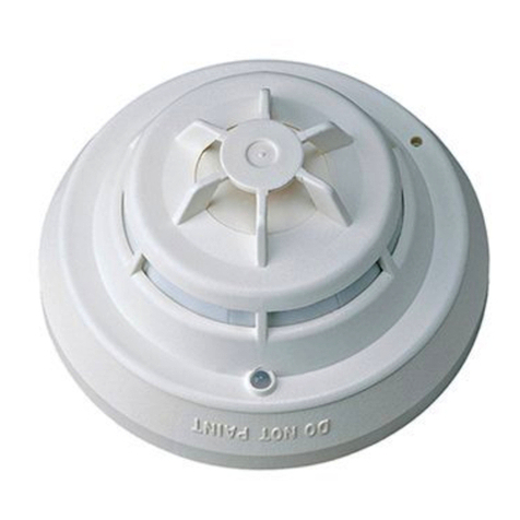
  9. Siemens AnalogPLUS DB1131A User manual

Siemens AnalogPLUS DB1131A User manual

x1243d
x1243c
DS11
7
Dokument-Nr. / Document no.
Ausgabe / Edition
Ersetzt / Remplace / Supersedes
Handbuch / Manuel / Manual
Register / Registre / Section
2016-04-20
&
AlgoRex®
Control Products and Systems
Siemens Building Technologies
1486 462x1243d 2016-04-20 Data and design subject to change without notice / Supply subject to availability
©Siemens Building Technologies AG
1Platzbedarf
Für Service- und Revisionsarbeiten muss
der montierte Melder gut zugänglich sein.
Melder müssen mit dem Melderaustau-
scher senkrecht von unten herausgenom-
men und geprüft werden können. Der
Sockel muss seitlich min. 2cm Spielraum
haben.
2Montagelage
Der Ansprechindikator im Melder muss
vom Erkundungsweg aus gut sichtbar
sein.
Montage bei Unterputz-Leitungsverle-
gung
1Encombrement
Une fois monté, l’embase doit être parfai-
tementaccessiblepourlestravauxderévi-
sion et pour le service. Les détecteurs doi-
vent pouvoir être retirés avec l’échangeur
de détecteur ou vérifiés verticalement et
par le bas. Respecter au minimum 2cm
d’éloignement par rapport aux obstacles.
2Position de montage
Lors de la reconnaissance, l’indicateur
d’action incorporé dans le détecteur doit
être parfaitement visible.
Montage lorsque les câbles sont posés
sous crépi
1Space requirements
For maintenance purposes the installed
base must be easily accessible. Ensure
that it is possible to extract the detector us-
ing exchanger or to test from a point di-
rectly below the base. The base must
have at least 2cm clearance on all sides.
2Mounting position
The position of the built-in response indi-
cator must ensure quick location of the de-
tector in alarm.
Installation with concealed wiring
DB1131A DB1131ADB1131A Base for Fire
Detectors Ana-
logPLUS®DS11
Embase pour détec-
teurs d’incendie
AnalogPLUS®DS11
Sockel für Brand-
melder Analog-
PLUS®DS11
Montageanleitung Instructions de montage Installation instructions
Ansprechindikator
Indicateur d’action
Response indicator
2
Melder
Détecteur
Detector
50cm
1
ÍÍÍÍÍÍÍÍÍÍÍÍÍÍ
ÍÍÍÍÍÍÍÍÍÍÍÍÍÍ
min. 2cm
ÓÓÓÓÓÓÓÓÓÓÓ
ÓÓÓÓÓÓÓÓÓÓÓ
ÓÓÓÓÓÓÓÓÓÓÓ
ÓÓÓÓÓÓÓÓÓÓÓ
ÓÓÓÓÓÓÓÓÓÓÓ
ÓÓÓÓÓÓÓÓÓÓÓ
Lage des Indikators beachten
Observer la position de l’indicateur
Note position of indicator
Ankommende und abgehende
Kabel einzeln dicht durchstossen
Passer séparément et de façon étan-
che les câbles arrivants et partants
Push through cables from last base
and to next base separately (tight fit)
Sockel
Embase
Base DB1131A
Schrauben
Vis
Screws max. 4mmø
UP-Dose
Boîte encastrée
Recess box
60...70mm
Control Products and Systems
Siemens Building Technologies
2 x1243d
2016-04-20
Data and design subject to change without notice / Supply subject to availability
©Siemens Building Technologies AG
Sockelzusatz, feucht
Auxiliaire d’embase pour application
humide
Base attachment for wet application
DBZ1192 (Art. Nr. 458 814)
Lage des Indikators beachten
Observer la position de l’indicateur
Note position of indicator
Lage des Indikators beachten
Observer la position de l’indicateur
Note position of indicator
Sockelzusatz verwenden
Utiliser auxiliaire d’embase
Use base attachment
DBZ1191 (Art. Nr. 454 083)
Gewünschte Leitungseinführung
ausbrechen
Ebrécher l’entrée des câbles désirée
Break out required entry point
ÓÓÓÓÓÓÓÓÓÓÓÓÓÓÓ
ÓÓÓÓÓÓÓÓÓÓÓÓÓÓÓ
ÓÓÓÓÓÓÓÓÓÓÓÓÓÓÓ
ÓÓÓÓÓÓÓÓÓÓÓÓÓÓÓ
ÓÓÓÓÓÓÓÓÓÓÓÓÓÓÓ
ÓÓÓÓÓÓÓÓÓÓÓÓÓÓÓ
ÓÓÓÓÓÓÓÓÓÓÓÓÓÓÓ
ÓÓÓÓÓÓÓÓÓÓÓÓÓÓÓ
ÓÓÓÓÓÓÓÓÓÓÓÓÓÓÓ
ÓÓÓÓÓÓÓÓÓÓÓÓÓÓÓ
ÓÓÓÓÓÓÓÓÓÓÓÓÓÓÓÓ
ÓÓÓÓÓÓÓÓÓÓÓÓÓÓÓÓ
ÓÓÓÓÓÓÓÓÓÓÓÓÓÓÓÓ
ÓÓÓÓÓÓÓÓÓÓÓÓÓÓÓÓ
ÓÓÓÓÓÓÓÓÓÓÓÓÓÓÓÓ
ÓÓÓÓÓÓÓÓÓÓÓÓÓÓÓÓ
ÓÓÓÓÓÓÓÓÓÓÓÓÓÓÓÓ
ÓÓÓÓÓÓÓÓÓÓÓÓÓÓÓÓ
ÓÓÓÓÓÓÓÓÓÓÓÓÓÓÓÓ
ÓÓÓÓÓÓÓÓÓÓÓÓÓÓÓÓ
ÓÓÓÓÓÓÓÓÓÓÓÓÓÓÓÓ
ÓÓÓÓÓÓÓÓÓÓÓÓÓÓÓÓ
Schrauben max. 4mmø
Sockel
Embase
Base DB1131A
Aufputz-Montage in trockener Montage sur crépi dans environne- Surface mounting for dry
Montage in feuchter Umgebung Montage dans environnement humide Mounting for wet application
Vis
Screws
Sockel
Embase
Base DB1131A
Umgebung ment sec application
Control Products and Systems
Siemens Building Technologies
3x1243d 2016-04-20 Data and design subject to change without notice / Supply subject to availability
©Siemens Building Technologies AG 486 462
ÓÓÓÓÓÓÓÓÓÓÓÓÓÓÓÓ
ÓÓÓÓÓÓÓÓÓÓÓÓÓÓÓÓ
ÓÓÓÓÓÓÓÓÓÓÓÓÓÓÓÓ
ÓÓÓÓÓÓÓÓÓÓÓÓÓÓÓÓ
ÓÓÓÓÓÓÓÓÓÓÓÓÓÓÓÓ
ÓÓÓÓÓÓÓÓÓÓÓÓÓÓÓÓ
ÓÓÓÓÓÓÓÓÓÓÓÓÓÓÓÓ
ÓÓÓÓÓÓÓÓÓÓÓÓÓÓÓÓ
ÓÓÓÓÓÓÓÓÓÓÓÓÓÓÓÓ
ÓÓÓÓÓÓÓÓÓÓÓÓÓÓÓÓ
ÓÓÓÓÓÓÓÓÓÓÓÓÓÓÓÓ
ÓÓÓÓÓÓÓÓÓÓÓÓÓÓÓÓ
ÓÓÓÓÓÓÓÓÓÓÓÓÓÓÓÓ
ÓÓÓÓÓÓÓÓÓÓÓÓÓÓÓÓ
ÓÓÓÓÓÓÓÓÓÓÓÓÓÓÓÓ
ÓÓÓÓÓÓÓÓÓÓÓÓÓÓÓÓ
ÓÓÓÓÓÓÓÓÓÓÓÓÓÓÓÓ
ÓÓÓ
ÓÓÓ
Melderkennzeichnungsschild
Plaque de désignation du détecteur
Detector designation plate
DBZ1193A (Art. Nr. 486 433)
Meldermarkierung
Marquage du détecteur
Detector marking
DBZ1193A-AA (Art. Nr. 500 982)
Bei eingesetztem Arretiernocken kann
der Melder nur mit einem Schraubenzie-
her entriegelt werden
Si l’embase est munie d’ergots de bloca-
ge, le détecteur ne peut être déverrouillé
qu’avec l’aide d’un tournevis
When locking stud is fitted, detector can
only be unlatched with a screwdriver
DBZ1190 (Art. Nr. 458 526)
Montagemasse
Dimensions
Dimensions
Zum Einschieben des Leiters, Fe-
derklemme mit Schraubenzieher
Nr. 0 (Klingenbreite max. 3,5mm)
entlasten
Pour insérer le conducteur, déga-
ger la borne à ressort avec un
tournevis no. 0 (largeur de la tige
3,5mm au max.)
In order to insert the wire, open
spring terminal with a screwdriver
no. 0 (blade width max. 3.5mm)
Anschluss Raccordement Connection
Draht einschieben
Insérer le fil
Insert wire
Drähte 8mm abisolieren
Dénuder les fils sur 8mm
Strip back 8mm insulation
Pro Klemme darf max. 1 Leiter
0,2-2,5mm2angeschlossen werden
1 conducteur de 0,2-2,5mm2au max.
peut être raccordé sur une borne
Max. one conductor of 0.2-2.5mm2in
each terminal
Marquage de l’indicateur d’action
Marking of response indicator
21
ø113
Markierung Ansprechindikator
47
70
4,3
Die Leiterschlaufen müssen flach
liegen und dürfen die Klemmen-
höhe nicht übersteigen
Les boucles de conducteurs doi-
vent reposer platement et ne pas
dépasser la hauteur des bornes
The conductor loops must lie flat
and must not be higher than the
terminals
max. Höhe für Verkabelung
hauteur max. pour câblage
max. height for cabling
Montageschablone
Gabarit de perçage
Drilling template
Melderkennzeichnungsschild, Meldermarkierung
Plaque de désignation, marquage du détecteur
Detector designation plate, detector marking
Control Products and Systems
Siemens Building Technologies
4 x1243d
2016-04-20
Data and design subject to change without notice / Supply subject to availability
©Siemens Building Technologies AG
22
2
11
0.28 ... 0.5mm2
1.0 ... 2.5mm2
Ausbrechen und Schutzkorb festschrauben
Ebrécher et serrer le corbeille protectrice
Break out and fasten the protective cage
DBZ1194 (Art. Nr. 467 711)
Zusatzklemme DBZ1190-AA/AB
Borne additionnelle
Auxiliary terminal
DJ1191
DJ1192 DJ1191
DJ1192
Melderschutzkorb
Corbeille protectrice
Protective cage
Max. 2 external response indicators per
base.
2 indicateurs d’action externes au max.
par embase.
Max. 2 externe Ansprechindikatoren pro
Sockel.
Melderbus
Bus de détection
Detector bus
+-
Externe Ansprechindikatoren (DJ1191/
DJ1192, DJ1193). Bei Ansteuerung von
mehr als einem Melder: Plus nur mit ei-
nem Sockel verbinden.
Indicateurs d’action externes (DJ1191/
DJ1192, DJ1193). Lors de l’asservisse-
ment de plus d’un détecteur: ne relier le
«plus» qu’avec une seule embase.
External response indicators (DJ1191/
DJ1192, DJ1193). When activated by
more than one detector, connect positive
only from one base.
Anschluss Meldelinie für Melder Ana-
logPLUS®Raccordement ligne de détection pour
détecteurs AnalogPLUS®Connection detection line for detec-
tors AnalogPLUS®
Achtung! Polarität beachten!
Attention! Considérer la polarité!
Important! Observe polarity!
+-+-
DJ1191
DJ1192
-
+
Option Ringleitung
Ligne circulaire optional
Optional Class «A» wiring
-
+
DB1131A DB1131ADB1131A
Option: Zusatzklemmen für Anschluss von 2 externen An-
sprechindikatoren oder Kabelabschirmung
Option: bornes additionnelles pour le raccordement de 2 indica-
teurs d’action externes ou blindage de câble
Option: Auxiliary terminals for connection of 2 external re-
sponse indicators or cable shielding
1
2
Pos Type
Querschnitt
Section
Cross-section
Zusatzklemme
Borne additionnelle
Auxiliary terminal
DBZ1190-AA
DBZ1190-AB
Zusatzklemmen
Bornes additionnelles
Auxiliary terminals
467 708
494 234
Control Products and Systems
Siemens Building Technologies
5x1243d Data and design subject to change without notice / Supply subject to availability
©Siemens Building Technologies AG
2016-04-20 486 462
Control Products and Systems
Siemens Building Technologies
6 x1243d
Data and design subject to change without notice / Supply subject to availability
©Siemens Building Technologies AG 2016-04-20
Issued by
Siemens Switzerland Ltd
Building Technologies Division
International Headquarters
Gubelstrasse 22
CH−6301 Zug
Tel. +41 41 − 724 24 24
www.siemens.com/buildingtechnologies

Other Siemens Fire Alarm manuals

Siemens DM1132 User manual

Siemens

Siemens DM1132 User manual

Siemens FC901 User guide

Siemens

Siemens FC901 User guide

Siemens FS720 Series Operating instructions

Siemens

Siemens FS720 Series Operating instructions

Siemens FireSeeker FS-100 User manual

Siemens

Siemens FireSeeker FS-100 User manual

Siemens FC700A Guide

Siemens

Siemens FC700A Guide

Siemens FDM223 User manual

Siemens

Siemens FDM223 User manual

Siemens MSI-30B User manual

Siemens

Siemens MSI-30B User manual

Siemens FP-11 FirePrint Reference manual

Siemens

Siemens FP-11 FirePrint Reference manual

Siemens HFPT-11 Service manual

Siemens

Siemens HFPT-11 Service manual

Siemens FDM223-Ex User manual

Siemens

Siemens FDM223-Ex User manual

Siemens FT2040 Instruction Manual

Siemens

Siemens FT2040 Instruction Manual

Siemens CERBERUS AlgoRex Series Instruction sheet

Siemens

Siemens CERBERUS AlgoRex Series Instruction sheet

Siemens SSD-C User manual

Siemens

Siemens SSD-C User manual

Siemens FDM275-O User manual

Siemens

Siemens FDM275-O User manual

Siemens Cerberus CS1140 Guide

Siemens

Siemens Cerberus CS1140 Guide

Siemens FDM365-RP User manual

Siemens

Siemens FDM365-RP User manual

Siemens Cerberus PRO FS720 User manual

Siemens

Siemens Cerberus PRO FS720 User manual

Siemens HMS-SZ User manual

Siemens

Siemens HMS-SZ User manual

Siemens FDMH294-R User manual

Siemens

Siemens FDMH294-R User manual

Siemens Synova FC330A User manual

Siemens

Siemens Synova FC330A User manual

Siemens MH-5 Series Service manual

Siemens

Siemens MH-5 Series Service manual

Siemens FDOOT271-O User manual

Siemens

Siemens FDOOT271-O User manual

Siemens MH-5 Series Service manual

Siemens

Siemens MH-5 Series Service manual
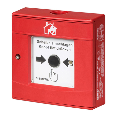
Siemens FDOOT241-9 User manual

Siemens

Siemens FDOOT241-9 User manual

Popular Fire Alarm manuals by other brands

Tyco F3200 Installation & configuration manual

Tyco

Tyco F3200 Installation & configuration manual

Aritech 1200C user manual

Aritech

Aritech 1200C user manual

Potter PFC-7500 installation manual

Potter

Potter PFC-7500 installation manual

Apollo SA5900-908 installation guide

Apollo

Apollo SA5900-908 installation guide

Ziton ZP755R-2 Installation sheet

Ziton

Ziton ZP755R-2 Installation sheet

System Sensor SP2R Installation and maintenance instructions

System Sensor

System Sensor SP2R Installation and maintenance instructions

Tyco TIS-BG12LX manual

Tyco

Tyco TIS-BG12LX manual

BR RABC Series manual

BR

BR RABC Series manual

Secutron MR-2300 series Addendum for Installation Instructions

Secutron

Secutron MR-2300 series Addendum for Installation Instructions

Autronica AutroSafe BS-3 manual

Autronica

Autronica AutroSafe BS-3 manual

System Sensor PS12/24ADA Series Installation and maintenance instructions

System Sensor

System Sensor PS12/24ADA Series Installation and maintenance instructions

Tyco F3200 Installation & programming manual

Tyco

Tyco F3200 Installation & programming manual

Zeta SP-64 User manual, maintenance guide & log book

Zeta

Zeta SP-64 User manual, maintenance guide & log book

Honeywell NOTIFIER IDR-M Installation and commissioning manual

Honeywell

Honeywell NOTIFIER IDR-M Installation and commissioning manual

GE Interlogix FP1500 Manual for installation, configuration and commissioning

GE

GE Interlogix FP1500 Manual for installation, configuration and commissioning

Maxlogic ML-221XX series user manual

Maxlogic

Maxlogic ML-221XX series user manual

UniPOS FD 7150 instruction manual

UniPOS

UniPOS FD 7150 instruction manual

GST DI-9204 quick start guide

GST

GST DI-9204 quick start guide

manuals.online logo
manuals.online logoBrands
  • About & Mission
  • Contact us
  • Privacy Policy
  • Terms and Conditions

Copyright 2025 Manuals.Online. All Rights Reserved.