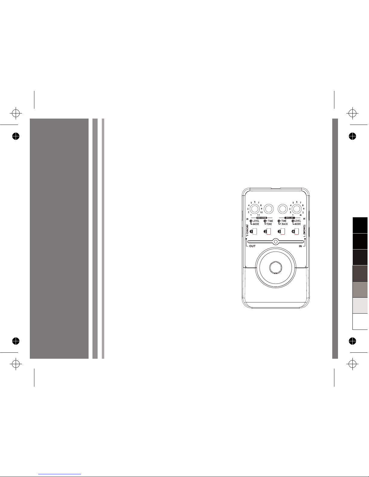
Medeli FD900 User manual

Owner's Manual
DIGITAL DELAY &
REVERB EFFECTS
PEDAL
0
5
25
75
95
100
aw_FD900_Manual_G07_101105
2010115 16:54:16

INFORMATION FOR YOUR SAFETY!
PRECAUTIONS
PLEASE READ CAREFULLY BEFORE PROCEEDING.
Please keep this manual in a safe place for future reference.
2
Power Supply
Please connect the designated AC adaptor to an AC
outlet of the correct voltage.
Do not connect it to an AC outlet of voltage other than
that for which your instrument is intended.
Unplug the AC power adaptor when not using the
instrument, or during electrical storms.
Connections
Before connecting the instrument to other devices, turn
off the power to all units. This will help prevent
malfunction and / or damage to other devices.
Location
Do not expose the instrument to the following
conditions to avoid deformation, discoloration, or more
serious damage:
Direct sunlight
Extreme temperature or humidity
Excessive dusty or dirty location
Strong vibrations or shocks
Close to magnetic fields
Interference with other electrical devices
Radios and televisions placed nearby may experience
reception interference. Operate this unit at a suitable
distance from radios and televisions.
Cleaning
Clean only with a soft, dry cloth.
Do not use paint thinners, solvents, cleaning fluids, or
chemical-impregnated wiping cloths.
Handling
Do not apply excessive force to the switches or controls.
Do not let paper, metallic, or other objects into the
instrument. If this happens, unplug the AC adaptor from
the wall outlet. Then have the instrument inspected by
qualified service personnel.
Disconnect all cables before moving the instrument.
CAUTION
The normal function of the product may be disturbed
by Strong Electro Magnetic Interference. If so,
simply reset the product to resume normal operation
by following the owner’s manual. In case the function
could not resume, please use the product in other
location.
0
5
25
75
95
100
aw_FD900_Manual_G07_101105
2010115 16:54:16

Contents
3
Panel Description
Front Panel
Setup
Battery Replacement Diagram 7
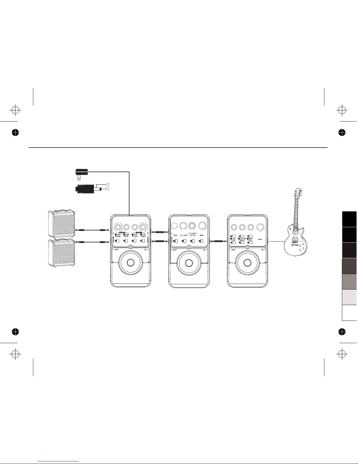
Connection 8
Effects Introduction
Effects List 10
Delay
01. 10 1000ms STEREO DELAY
02. 1000~3000ms STEREO DELAY 11
03. 100~3000ms PAN MOD. DELAY
04. 10~500ms MONO DELAY 11
05. 500~1000ms MONO DELAY 11
06. 1000~6000ms MONO DELAY 11
07. 10~1000ms ANALOG DELAY 11
08. 10~1000ms MODULATED DELAY 12
09. 100~3000ms REVERSE DELAY 12
10. 100~12000ms SOUND ON SOUND DELAY
Reverb
01. ROOM I REVERB...
02. ROOM II REVERB
03. HALL I REVERB
04. HALL II REVERB
.........................................................
............................
.........................................................
......................................................
..........................10
.......................
.......................11
................................
............................
..........................
..........................
....................
.......................
.......12
.........................................14
.........................................14
..............................................14
.............................................14
4
~
05. HALL III REVERB 14
06. CHURCH REVERB 14
07. SPRING REVERB 14
08. PLATE REVERB 14
09. REVERSE REVERB 14
10. GATE REVERB 14
11. MODULATE REVERB 14
Store and Recall Patches
Storing Your Favorite Tones 15
Recalling the Saved Memories 6
Advanced Use
Footswitch Control Mode 17
Effect Trails Mode 18
Bypass Pan Mode 19
20
Troubleshooting 22
Specifications 24
Appendices
Setting Samples 25
..........................................
..........................................
.......................................
.........................................
...........................................
......................................
.............................................
....................................
............................
.......................1
................................
...........................................
...........................................
Tap Tempo Delay............................................
............................................
................................................
..............................................
0
5
25
75
95
100
aw_FD900_Manual_G07_101105
2010115 16:54:17

Panel Description
Front Panel
4
11
12
14 13
0
5
25
75
95
100
aw_FD900_Manual_G07_101105
2010115 16:54:17

Panel Description
5
1. REVERB MODE Knob:
Select one kind of reverb among the 11 reverb
modes.
2. REVERB LEVEL Knob:
Control the effect level of reverb.
3. REVERB TIME Knob:
Control the delay time of reverb.
4. REVERB TONE Knob:
Control the tone of reverb.
5. DELAY TIME Knob:
Control the delay time.
6. DELAY F.BACK Knob:
Control the feedback of delay.
7. DELAY MODE Knob:
Select one kind of delay among the 10 delay
modes, or to select the patch memory function.
8. DELAY LEVEL Knob:
Control the effect level of delay.
9. PATCH MEMORY Buttons:
Press and hold anyone of the PATCH
MEMORY buttons to store your favorite tones.
When the “DELAY MODE” knob on the M
position is selected, press any PATCH
MEMORY button to recall the tone you stored.
10. ON/OFF LED:
Indicate the on/off status of the unit.
11. FOOTSWITCH:
Press the switch to turn effects on and off or
for patch memory selection.
12. POWER Jack:
Plug the 9V power adaptor into this jack.
0
5
25
75
95
100
aw_FD900_Manual_G07_101105
2010115 16:54:17

13. INPUT Jack:
IN-L(MONO): Connect your guitar to this jack.
Connect a guitar cable to this jack for power
supply when using a battery.
IN-R: Connect another guitar to this jack.
Notice:
You can also connect a stereo signal to this 2
combinational input jack, such as keyboard,
synth, electronic drum, audio player, and so on.
14. OUTPUT Jack:
OUT-L(MONO): Connect this output jack to
your guitar amplifier.
OUT-R: Connect this output jack to another
amplifier.
Notice:
You can also send this 2 combinational output
jack's stereo signal to amplifier, mixer, audio
interface, or another effect processor.
6
Panel Description
0
5
25
75
95
100
aw_FD900_Manual_G07_101105
2010115 16:54:17

Setup
7
Battery Replacement Diagram
Warning:
1. A 9V battery must be installed
before you plug the mono audio cable into
the input jack.
2. While the power supply is low, the LED will
extinguish. Please replace the battery
accordingly.
3. Turn the guitar amplifier off before plugging
and unplugging cables, otherwise
tremendous noise might be produced and
the unit might be damaged as well.
(optional)
0
5
25
75
95
100
aw_FD900_Manual_G07_101105
2010115 16:54:17

8
Connection
Connection
1. Connect the optional power supply to the
power jack or insert a 9V battery (optional)
into the battery compartment on the bottom.
2. Connect your guitar to input jack and an
amplifier to output jack of the Pedal.
3. The Pedal will automatically switch on after a
cable is plugged into its L-input jack when
using a battery.
Use only the appropriate adaptor with the
correct voltage and with a center NEGATIVE
polarity. Some adaptors are made with a
different polarity or voltage, which may
damage the unit if it has been falsely used in
connection.
AC Adaptor
OUT DC 9V
-
+
OUT L (MONO)
OUT L
OUT R
Amplifier II
Amplifier I
0
5
25
75
95
100
aw_FD900_Manual_G07_101105
2010115 16:54:18

OUT L
OUT R
Amplifier II
Amplifier I
AC Adaptor
OUT DC 9V
-
+
9
Connection
0
5
25
75
95
100
aw_FD900_Manual_G07_101105
2010115 16:54:18

Effects Introduction
10
This is a digital delay and reverb effects pedal,
contains 10 excellent delay effects and 11 excellent
reverb effects. It also includes the storage
function, allows you to store and recall up to 4 patch
memories.
Effects List
NO.
1
2
3
4
5
6
7
8
9
S
DELAY MODE
10~1000ms STEREO DELAY
1000~3000ms STEREO DELAY
100~3000ms PAN MOD. DELAY
10~500ms MONO DELAY
500~1000ms MONO DELAY
1000~6000ms MONO DELAY
10~1000ms ANALOG DELAY
10~1000ms MODULATED DELAY
100~3000ms REVERSE DELAY
200~12000ms SOUND ON SOUND DELAY
NO.
1
2
3
4
5
6
7
8
9
10
11
REVERB MODE
ROOM I REVERB
ROOM II REVERB
HALL I REVERB
HALL II REVERB
HALL III REVERB
CHURCH REVERB
SPRING REVERB
PLATE REVERB
REVERSE REVERB
GATE REVERB
MODULATE REVERB
0
5
25
75
95
100
aw_FD900_Manual_G07_101105
2010115 16:54:18

Delay
01. 10~1000ms STEREO DELAY
02. 1000~3000ms STEREO DELAY
Stereo delay effects. Requires stereo inputs.
Send the left input signal to reverb left input, the
right input signal to reverb right input through
delay process.
03. 100~3000ms PAN MOD. DELAY
Pan modulator delay effects (ping-pang delay).
Send the left input signal to reverb input through
delay process.
04. 10~500ms MONO DELAY
05. 500~1000ms MONO DELAY
06. 1000~6000ms MONO DELAY
Mono delay effects. Send the left input signal to
reverb input through delay process.
07. 10~1000ms ANALOG DELAY
Analog delay effects, emulates a vintage delay
sound. Send the left input signal to reverb input
through delay process.
11
Effects Introduction
DELAY
DELAY
L-INPUT
R-INPUT
To REVERB L-INPUT
To REVERB R-INPUT
DELAYL-INPUT To REVERB L-INPUT
To REVERB R-INPUT
DELAYL-INPUT To REVERB L-INPUT
To REVERB R-INPUT
DELAYL-INPUT To REVERB L-INPUT
To REVERB R-INPUT
0
5
25
75
95
100
aw_FD900_Manual_G07_101105
2010115 16:54:18

Effects Introduction
08. 10~1000ms MODULATED DELAY
Modulated delay effects, add some chorus
effects. Send the left input signal to reverb input
through delay process.
09. 100~3000ms REVERSE DELAY
Reverse delay effects, the repeating sound are
played backwards. Send the left input signal to
reverb input through delay process.
10. 100~12000ms SOUND ON SOUND DELAY
Recording delay effects, can create infinite loops
of up to 12 seconds in length. Send the left input
signal to reverb input through delay process.
When the DELAY MODE point to this position, press
and hold the FOOT SWITCH and immediately start
playing. The indicator LED (ON/OFF) will be lighted,
at the time, the pedal can record your playing sound.
When you release the FOOT SWITCH, the LED
(ON/OFF) will be flashing, it begins to play the
sound recorded. To add overdubs to the existing
loop, press and hold the FOOT SWITCH again, then
the loop will be added.
12
DELAYL-INPUT To REVERB L-INPUT
To REVERB R-INPUT
DELAYL-INPUT To REVERB L-INPUT
To REVERB R-INPUT
DELAYL-INPUT To REVERB L-INPUT
To REVERB R-INPUT
RECORDING PLAYING
0
5
25
75
95
100
aw_FD900_Manual_G07_101105
2010115 16:54:18

Effects Introduction
13
After first recording, M1~M4 will be lighted one by
one to show the beat. The light will keep on showing
till the memory is cleared.
To stop the loop, there are two methods:
1> Turn DELAY MODE to other positions.
2> Quickly press the FOOTSWITCH.
When using SOUND ON SOUND DELAY, turn
DELAY LEVEL knob to adjust the volume of loop,
both DELAY F.BACK knob and DELAY TIME knob
are unavailable.
Whether the LED (ON/OFF) is lighted, REVERB
effects can be adjusted normally.
0
5
25
75
95
100
aw_FD900_Manual_G07_101105
2010115 16:54:18

Effects Introduction
14
Reverb
01. ROOM I REVERB
02. ROOM II REVERB
Simulate the reverb sound of room with
different size.
03. HALL I REVERB
04. HALL II REVERB
05. HALL III REVERB
Simulate the reverb sound of halls from small
to large.
06. CHURCH REVERB
Simulate the reverb sound of church, the
sound is holy and persisting.
07. SPRING REVERB
Simulate the sound of a amp's built-in spring
reverb, it's flexible.
08. PLATE REVERB
Simulate a type of reverb sound caused by
a metal plate, it provides a metallic reverb
sound with extended high-band ending.
09. REVERSE REVERB
Reverse reverb, a fancy reverb sound.
10. GATE REVERB
Gate reverb, set a gate to control the reverb
sound, affected by input.
11. MODULATE REVERB
Modulate reverb, add chorus effect into
reverb, nice extensity.
0
5
25
75
95
100
aw_FD900_Manual_G07_101105
2010115 16:54:18

Storing Your Favorite Tones
You can store your favorite tones into one of the 4
patches when the pedal DELAY MODE knob is
turned to a position between DELAY MODE 1~9 and
the ON/OFF LED indicator is on at the same time.
Notice:
Because of the particularity on “SOUND ON
SOUND” delay, when the DELAY MODE point to S
position, the tone can not be stored.
For example, if you want to store the current setting
to patch 2, you should press the 2nd button (as
shown in the diagram) and hold for at least 0.5
second. The ON/OFF LED indicator has to be on at
the same time.
Then, all LED indicators of the padel will light up
from 1 to 4 in a slow speed:
Store and Recall Patches
15
0
5
25
75
95
100
aw_FD900_Manual_G07_101105
2010115 16:54:18

Store and Recall Patches
Press and hold the 2nd button for another 2 seconds
to enter the storage function; all LED indicators will
flash from 1 to 4 in a fast speed.
You can then release the button. The LED indicator
of this button will be lighted for the final one second,
then the whole action will stop; your own setting has
already been stored into the chosen patch.
Finally, it returns to the normal mode automatically:
Recalling the Saved Memories
If you want to recall the patches that you have saved,
you must turn the DELAY MODE knob to the M
position:
At this time, the LED indicator of the latest stored
patch will be lighted automatically.
For example, if you want to recall patch 1, just press
the 1st button:
When the DELAY MODE knob points to the M
position, all knobs will be inactivated.
16
0
5
25
75
95
100
aw_FD900_Manual_G07_101105
2010115 16:54:19

Advanced Use
FOOT SWITCH Control Mode
When DELAY MODE knob points to the M position,
the FOOT SWITCH will provide two function modes.
Before making connection or powers on the padel,
turn the DELAY MODE knob to the M position, then
press and hold the FOOT SWITCH firmly; then
power up the unit and keep holding the FOOT
SWITCH until the ON/OFF LED indicator flashes
three times(When using a battery, press and hold the
FOOT SWITCH firmly, then plug INPUT and keep
holding the FOOT SWITCH until the ON/OFF LED
indicator flashes three times).
The FOOT SWITCH control mode will be changed
from the status of “MODE.1” to “MODE.2”. You
can hit the FOOT SWITCH to swap from one patch
to another in sequence.
If you do not press and hold the FOOT SWITCH
before first powers on, the pedal will enter the
default mode MODE1.
Notice:
FOOT SWITCH Control Mode setting will be saved
after power off. Under Mode2, when DELAY MODE
knob points to the M position, PATCH MEMORY
Buttons are not available for pressing.17
MODE
MODE 1
MODE 2
FUNCTION
FOOT SWITCH for the bypass function as
usual.
FOOT SWITCH swaps between the patch
memories in the sequence of Button (Patch)
01→02→03→04
0
5
25
75
95
100
aw_FD900_Manual_G07_101105
2010115 16:54:19

Advanced Use
Effect Trails Mode
There are two function modes to enter BYPASS.
Users can choose whether keep the effect sound
persisting when entering BYPASS.
The default BYPASS entry mode is MODE 1,to
switch it to MODE 2, before making connection or
powers on the padel, turn the DELAY MODE knob to
the 1 position, then press and hold the FOOT
SWITCH firmly; then power up the unit and keep
holding the FOOT SWITCH until the ON/OFF LED
indicator flashes three times(When using a battery,
press and hold the FOOT SWITCH firmly, then plug
INPUT and keep holding the FOOT SWITCH until
the ON/OFF LED indicator flashes three times).
To set MODE 1 back, do the same operation.
Notice:
Effect Trails Mode setting will be saved after power
off.
18
MODE
MODE 1
MODE 2
FUNCTION
When pressing FOOT SWITCH to enter
BYPASS, the effect sound will be stopped.
When pressing FOOT SWITCH to enter
BYPASS, the effect sound will persist.
0
5
25
75
95
100
aw_FD900_Manual_G07_101105
2010115 16:54:19

Advanced Use
Bypass Pan Mode
There are two function modes to select pan setting
at BYPASS state. When BYPASS, the default
BYPASS pan mode (MODE 1) of the pedal is setting
like these:
STEREO DELAY MODE:
L-OUTPUT = L-INPUT
R-OUTPUT=R-INPUT
The rest modes:
L-OUTPUT= R-OUTPUT=L-INPUT
In MODE 2, BYPASS pan setting of all the delay
modes is the same way as STEREO DELAY under
MODE 1:
L-OUTPUT = L-INPUT
R-OUTPUT=R-INPUT
The default BYPASS pan mode is MODE 1,to
switch it to MODE 2, before making connection or
powers on the pedal, turn the DELAY MODE knob to
the 2 position, then press and hold the FOOT
SWITCH firmly; then power up the unit and keep
holding the FOOT SWITCH until the ON/OFF LED
indicator flashes three times(When using a
19
MODE
MODE 1
MODE 2
FUNCTION
STEREO DELAY: L-OUTPUT = L-INPUT,
R-OUTPUT=R-INPUT
Rest Delay Modes:
L-OUTPUT= R-OUTPUT=L-INPUT
All the Delay Modes: L-OUTPUT =
L-INPUT, R-OUTPUT=R-INPUT
0
5
25
75
95
100
aw_FD900_Manual_G07_101105
2010115 16:54:19

Advanced Use
20
battery, press and hold the FOOT SWITCH firmly,
then plug INPUT and keep holding the FOOT
SWITCH until the ON/OFF LED indicator flashes
three times).
To set MODE 1 back, do the same operation.
Notice:
BYPASS Pan Mode setting will be saved after
power off.
Tap Tempo Delay
The pedal offers a tap tempo function which can
make practice or live performance more
convenient. To use this function, please follow
these steps below:
When BYPASS, and DELAY MODE point to any
mode except S and M, press and hold the FOOT
SWITCH for 2 seconds, at the time, LED begin to
flash, imply entering the tap tempo delay function,
then you can release the FOOT SWITCH.
After entry, press FOOT SWITCH twice or more to
set the DELAY TIME, the interval is just the right
time. Then LED will flash in step with the time to
show the tempo. To set another DELAY TIME,
repeat the operation above.
Notice:
DELAY TIME knob is inactivated when using
tap tempo delay. When entering tap tempo
function, the delay time will be the same as the
value of current DELAY TIME knob's position.
To quit tap tempo delay function, press and
hold FOOT SWITCH for 2 seconds, or turn
DELAY MODE to other position.
If the interval between pressing FOOT SWITCH
twice is shorter than the minimal DELAY TIME
of the current mode, the setting is just the
minimal DELAY TIME of this mode; If longer,
tap tempo will keep the current tempo and take
count of a new round.
Notice:
When in different Delay Modes, the time range
of tap tempo function is the same as this Delay
Mode's time range. For example, when using
tap tempo in Analog Delay Mode, the delay
time you can set by "Tap" is from
10ms~1000ms, the same as the original range.
0
5
25
75
95
100
aw_FD900_Manual_G07_101105
2010115 16:54:19
Table of contents
Other Medeli Music Pedal manuals